Table of Contents
Advertisement
Quick Links
Advertisement
Table of Contents
Troubleshooting

Related Manuals for Keithley PIO-12


Summary of Contents for Keithley PIO-12
- Page 1 Artisan Technology Group is your source for quality new and certified-used/pre-owned equipment SERVICE CENTER REPAIRS WE BUY USED EQUIPMENT • FAST SHIPPING AND DELIVERY Experienced engineers and technicians on staff Sell your excess, underutilized, and idle us at our full-service, in-house repair center We also offer credit for buy-backs and tra •...
- Page 2 ■ ■ P10-12 User's Guide Revision D - April 1994 Part Number: 64190...
- Page 3 The information contained in this manual is believed to be accurate and reliable. However, Keithley Instruments, Inc., assumes no responsibility for its use or for any infringements of patents or other rights of third parties that may result from its use. No license is granted by implication or otherwise under any patent rights of Keithley Instruments, Inc.
-
Page 4: Table Of Contents
4 P r o g r a m m i n g Port Configuration 4 Programming Examples4 Writing the Control Register4 Basic I/0 Operations4 Reading BCD Data4 Bit Operations4 Programming Notes4 Interpreted Basic4 I/O Commands 4 PIO-12 Interrupt Channel 4 Assembly Language 4... - Page 5 Index List of Figures Figure 1-1. B l o c k Diagram of the PIO-12 Figure 2-1. S w i t c h and Jumper Locations Figure 3-1. P i n Assignments for the Main I/O Connector ..3-1 Figure 3-2.
-
Page 6: Preface
• C h a p t e r 5 describes common problems and solutions, troubleshooting procedures, and how to obtain technical support. • A p p e n d i x A contains PIO-12 specifications. • A p p e n d i x B contains pin assignments for the main connector of the... -
Page 8: General Description
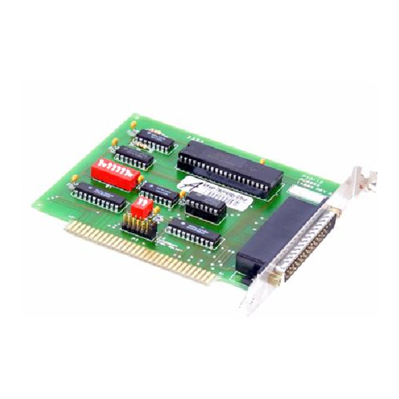
Overview ■ General Description The P10-12 is a 24-line, parallel, digital I/O interface board for IBM PC/XT, PC AT, and compatible computers. This board provides a flexible interface for a variety of parallel I/O devices, including instruments, displays and user-assembled systems. Figure 1-1 shows a block diagram of the P10-12. -
Page 9: Features And Operating Characteristics
Features and Operating Characteristics P10-12 features and operating characteristics are described as follows: • T h e PIO-12 has three TTL/CMOS-compatible, digital I/O ports: port A, port B, and port C. Ports A and B are both byte-wide (8-bits) and can be inputs or outputs. - Page 10 I/O modules with functions of DC input, DC output, AC input, and AC output. The SSIO-24 connects to the main 1/0 connector of the PIO-12 through a C-1800 cable. • S R A - 0 1 - 8-channel mounting panel for up to eight solid-state, miniature I/O modules.
-
Page 12: Unpacking And Inspecting
Installation This chapter contains instructions for installing the P10-12 board. The installation task includes three basic steps: unpacking and inspecting the board, setting the configuration switches and jumpers, and installing the board in the computer. These steps are described in the sections that follow. -
Page 13: Setting The Switches And Jumpers
3. Check the remaining contents of your package against the packing list to be sure your order is complete. Report any missing items, immediately. 4. W h e n you are satisfied with the inspection, proceed with the software and hardware setup instructions. Setting the Switches and Jumpers The base address, interrupt level, and J8 slot/wait state option are all specified through switch or jumper settings. -
Page 14: Setting The Base Address2
Setting the Base Address The base address switch is preset at the factory for 300h (see Figure 2-1). If this address is already assigned to some other device in your computer, you must set this switch for a different address. The address you specify must be within the range of 200 to 3FCh (512 to 1020 decimal) and on a 4-byte boundary. -
Page 15: Setting The J8 Slot/Wait State Switch
Table 2-2. Standard Address Assignments (cont.) Address Device A d d r e s s Device 210 - 217 Expansion unit 3 9 0 - 39F Available 218 - 21F Available 3 A 9 * Binary comm. 220 - 24F Reserved - 3AF Available... -
Page 16: Installing The Board
Table 2-3 lists the industry-standard usage for interrupts 2 to 7; use this table as a guide when selecting an interrupt level. Table 2-3. Standard Interrupt Usage Interrupt (IRO) Usage Level (if device exists) Reserved (XT), IRQ 8 to 15 (15) or SDLC COM I or SDLC Hard disk (XT), LPT (AT) -
Page 17: Using Power From The Pio-122
Using Power from the P10-12 Power from the computer supply is available on the main I/O connector of the P10-12. In situations where the P10-12 is used with a dedicated peripheral (for example, a switch pad) and the cabling and design loads are fixed, you may find it more appropriate to use the P10-12 power outputs. -
Page 18: Figure 3-1. Pin Assignments For The Main I/O Connector
Cabling and Wiring This chapter describes the cabling and wiring required for attaching accessories and 1/0 lines to the main I/O connector of your PIO-12 boards. The main 1/0 connector of the P10-12 is a 37-pin D-type. Pin assignments for this connector are shown in Figure 3-1. -
Page 19: A B L I N G And Wiring
Attaching Accessories The following accessories attach to the P10-12 through a C-1800 or S-1800 cable, as shown in Figure 3-2: • S T A - U screw terninal accessory. • S S I O - 2 4 12-channel mounting panel for I/0 modules. •... -
Page 20: Attaching An Stc-37 Accessory
Attaching an STC-37 Accessory The STC-37 is a screw terminal panel that appears as shown in Figure 3-3. D-Connector that connects to the P10-12 main I/O connector Cable Clamp Figure 3-3. Layout of STC-37 Screw Terminal Connector Panel... -
Page 21: Figure 3-4. Attaching An Stc-37 Accessory
The STC-37 connects to the P10-12 main I/O connector as shown in Figure 3-4. The screw terminal numbers of the STC-37 correspond to the pin numbers of the main I/O connector. STC-37 P10-12 board Figure 3-4. Attaching an STC-37 Accessory and Wiring... - Page 22 8-bit data input buffer. This port can also be used as two 4-bit ports: PC Upper (PC4 to PC7) and PC Lower (PCO to PC3). Programming the PIO-12 involves two fundamental tasks: setting the port configuration and reading/writing data from/to the ports. These tasks are discussed in the sections that follow.
-
Page 23: Port Configuration
Port Configuration Each port or half-port is configured as an input or an output according to the value of the control word in the PPI control register. The control word is 1-byte word programmed at Base Address +3. Refer to Table 4-1 for the complete 8255 PPI address map. -
Page 24: Table 4-2. D E R I V A T I O N Of Port Configuration From
configuration. Table 4-2 illustrates how the port configuration is derived from the control word. Table 4-2. D e r i v a t i o n of Port Configuration f r o m Control Word Bit # Setting C o n f i g u r a t i o n Bit set/reset mode for PCO to PC7 Mode set active for PCO to PC7 6 and 5... -
Page 25: Control Word
To simplify your selection of a control word to match your choice of port directions, use Table 4-3. This atble summarizes information from the Intel peripheral data book on control words and their port directions for mode 0. Table 4-3. P I O Control Word Port C P o r t C Control Word Port A... -
Page 26: Programming Examples4
Programming Examples The examples presented below use the BASIC programming language to illustrate some of common programming tasks. Line numbers in these examples were arbitrarily selected; these examples will work with any valid line numbering scheme. Writing the Control Register The following code specifies 300h as the base address of the P10-12, then configures all of the ports as outputs: 10 B A D D R = &... -
Page 27: Programming Notes4
The following code sets Bit 3 on Port A to 1 without disturbing the other bits: 30 A % = I N P ( B A D D R ) ' R e a d p o r t A . 40 O U T B A D D R , ( A % O R 2 ^ 3 ) ' O R b i t 3 a n d w r i t e t o ' P o r t A . -
Page 28: Pio-12 Interrupt Channel
I/O instructions to the same port address. This is due to recovery time requirements on the I/O peripheral circuits and is not related to the PIO-12 design. Because of this limitation, the use of code similar to the following is not recommended. -
Page 30: Troubleshooting
Problem Isolation I f you encounter a problem with a PIO-12 board, use the instructions in this section to isolate the cause of the problem before calling Keithley MetraByte Hardware Applications Engineering. -
Page 31: Table 5-1. Troubleshooting Information
The board is incorrectly aligned Check the board for proper seating. in the accessory slot. The board is damaged. Contact the Keithley MetraByte Hardware Applications Engineering Department; see "Technical Support" on page 5-5. Reduce I/O bus speed to a maximum of... -
Page 32: Testing The Board And Host Computer
Table 5-1, continue with the next two sections to further isolate the problem. Testing the Board and Host Computer To isolate the problem to the PIO-12 board or to the host computer, use the following steps: 1. T u r n the power to the host computer OFF, and remove power connections to the computer. -
Page 33: Testing The Accessory Slot And I/O Connections
2. W h i l e keeping connections to accessory board intact, unplug the accessory connector or cable from the P10-12 board. 3. Remove the PIO-12 board from the computer and visually check for damage. If a board is obviously damaged, refer to "Technical Support"... - Page 34 6. I f you cannot isolate the problem, refer to the next section for instructions on obtaining assistance. Technical Support Before returning any equipment for repair, call the Keithley MetraByte Hardware Applications Engineering Department at: (508) 880-3000 Monday - Friday, 8:00 A.M. - 6:00 P .M., Eastern Time...
- Page 35 An applications engineer will help you diagnose and resolve your problem over the telephone. Please make sure that you have the information page available before you call: P10-12 Board M o d e l Configuration S e r i a l # Revision code Base address setting Interrupt level setting...
- Page 36 Notes: I f you are submitting your equipment for repair under warranty, you must include the invoice number and date of purchase. To enable Keithley Metrabyte to respond as quickly as possible, you must include the RMA number on the outside of the package.
-
Page 38: Table A-1. Input And Output Specifications
CMOS compatibility can be achieved by connecting a 10 IcS2 pullup resistor from the PI)-12 output to +5 V. Table A-1 and Table A-2 list PIO-12 specifications. Table A-1. Input and Output Specifications Logic Inputs and Outputs 1 Minimum j Maximum Input logic low voltage - 0 . -
Page 39: Table A-2 Environmental Specifications
Table A-2. Environmental Specifications Feature Specification Bus-loading power consumption 170 mA Operating temperature range 0 to 500 C Stoarge temperature range -40 to 1000 C 0 to 90% noncondensing Humidity Dimensions 5 inches L x 4.25 inches H x 0.75 inches (12.7 cm x 10.8 cm x 1.9 cm) 4 oz. -
Page 40: Figure B-1. Main I/O Connector Pin Assignments
Connector Pin Assignments The connection between an external I/O device and the PIO-12 is made at the main I/O connector, which is a standard 37-pin, D-type male connector. The mating connector is a 37-pin, D-type female connector (part# SFC-37). Figure B-1 illustrates pin assignments of the P10-12 main I/O connector. -
Page 42: Index
Index data input latch 4-1 digital I/O ports 1-2 accessories, attaching 3-2 accessory ERA-01 1-3 ERA-01 accessory 1-3 ERB-24 1-3 ERB-24 accessory 1-3 SRA-01 1-3 examples, programming 4-5 SSIO-24 1-3 STA-U 1-2 STC-37 1-3 anti-static wrapping material 2-1 assembly language 4-7 factory-default settings 2-2 attaching features and operating characteristics 1 -2... - Page 43 I/0 devices 1-1 pin assignments B-1 port configuration 4-2, 4-3 unpacking and inspecting 2-1 power levels 1-2 using power from the PIO-12 2-6 PPI address map 4-2 using the interrupt channel 4-7 PPI, 8255 4-1 problem isolation 5-1 programming examples 4-5...
- Page 44 Artisan Technology Group is your source for quality new and certified-used/pre-owned equipment SERVICE CENTER REPAIRS WE BUY USED EQUIPMENT • FAST SHIPPING AND DELIVERY Experienced engineers and technicians on staff Sell your excess, underutilized, and idle us at our full-service, in-house repair center We also offer credit for buy-backs and tra •...
Need help?
Do you have a question about the PIO-12 and is the answer not in the manual?
Questions and answers