
Subscribe to Our Youtube Channel
Related Manuals for Keithley DDA-06


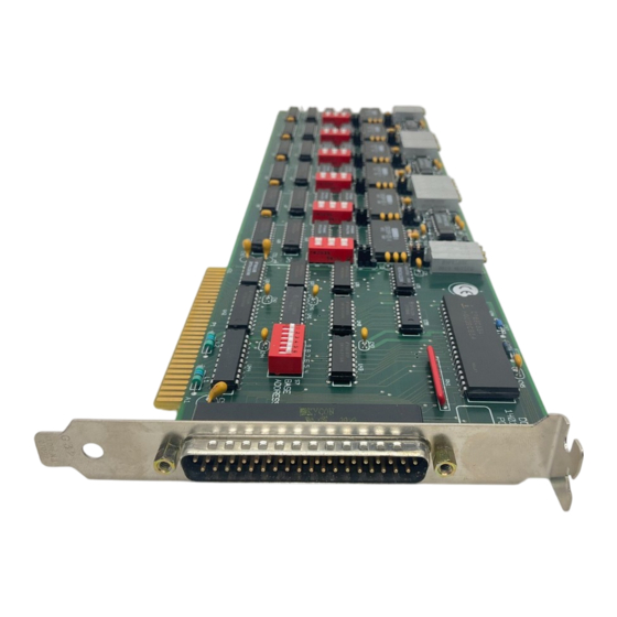
Summary of Contents for Keithley DDA-06
- Page 1 (217) 352-9330 | Click HERE Find the Keithley DDA-06 at our website:...
- Page 2 DDA-06 U S E R ’ S G U I D E Artisan Technology Group - Quality Instrumentation ... Guaranteed | (888) 88-SOURCE | www.artisantg.com...
- Page 3 DDA-06 User’s Guide Revision B - July 1994 Part Number: 61860 Artisan Technology Group - Quality Instrumentation ... Guaranteed | (888) 88-SOURCE | www.artisantg.com...
- Page 4 Keithley Instruments, Inc. 28775 Aurora Road Cleveland, OH 44139 Technical Support: 1-888-KEITHLEY Monday – Friday 8:00 a.m. to 5:00 p.m (EST) Fax: (440) 248-6168 Visit our website at http://www.keithley.com Artisan Technology Group - Quality Instrumentation ... Guaranteed | (888) 88-SOURCE | www.artisantg.com...
- Page 5 The information contained in this manual is believed to be accurate and reliable. However, Keithley Instruments, Inc., assumes no responsibility for its use or for any infringements of patents or other rights of third parties that may result from its use. No license is granted by implication or otherwise under any patent rights of Keithley Instruments, Inc.
- Page 6 Preface The DDA-06 User’s Guide is intended to help you understand the installation, interface requirements, functions, and operation of the DDA-06 board. This guide focuses primarily on describing the board and its capabilities, setting up the board and its associated software, making typical hookups, and operating the Control Panel software.
- Page 7 Chapter 8 contains information on isolating and determining the source of operating problems. This chapter also contains instructions for obtaining technical support. Appendix A contains specifications for the DDA-06 board. Appendix B contains pin assignments for the main I/O connector of DDA-06 board.
-
Page 8: Table Of Contents
Table of Contents Preface Overview Features and Applications ......1-1 Supporting Software........1-2 Accessories. - Page 9 List of Figures Figure 2-1. Block Diagram of DDA-06 ....2-1 Figure 3-1. Switch and Jumper Locations ....3-3 Figure 4-1.
- Page 10 Range Switch Settings ..... .3-5 Table 6-1. DDA-06 Register I/O Address Map ...6-1 Table 6-2.
-
Page 11: Overview
Overview The DDA-06 is a digital I/O and analog output board for an accessory slot of an IBM PC/XT, PC AT, or compatible computer. This chapter lists features and applications of the board and describes supporting software and accessories. Features and Applications... -
Page 12: Supporting Software
Supporting Software The software package for the DDA-06 is provided on 3.5-inch or 5.25-inch diskettes. This package includes example programs in ® ™ Microsoft QuickBasic 4.5, Microsoft Professional BASIC, C, Pascal, ™ and Microsoft Visual Basic for Windows. The package also includes support files and the following utility programs:... -
Page 13: Accessories
C-1800 - An 18-inch ribbon cable terminated at each end with a 37-pin female type D connector. STC-37 - Screw terminal connector panel. This accessory connects directly the the main I/O connector of a DDA-06 board to provide general-purpose, screw-terminal connections in a compact form factor. -
Page 14: Functional Description
DDA-06 board. These descriptions are provided to familiarize you with the operating options and to enable you to make the best use of your board. Figure 2-1 shows a block diagram of the DDA-06 board. Out 5... -
Page 15: Digital I/O Features
8-bit ports. Each of these ports can be independently programmed as an input or an output and is TTL/CMOS compatible. The DDA-06 uses an 8255 P.P.I. (programmable peripheral interface) chip for digital I/O; this chip can operate in any of the 8255 modes (modes 0 to 2), which are straight I/O, strobed I/O, and bidirectional I/O. -
Page 16: Setup And Installation
Use the following procedure to unwrap and inspect a DDA-06 board. 1. Factory packaging of the DDA-06 board includes a final wrap of protective, anti-static material. Remove the board from its anti-static wrapping material. You may wish to store the wrapping material for possible future use. -
Page 17: Installing The Software Package
Installing the Software Package Before you work with the DDA-06 software, copy the software package diskette either to your computer hard drive or to another diskette. To copy the software to your computer hard drive, make a new directory to contain the software, such as DDA06. -
Page 18: Setting The Base Address
DAC 0 DAC 1 DAC 2 DAC 3 DAC 4 DAC 5 Output Mode Jumper Data 1 2 3 4 5 6 Transfer Base Address Range Jumper Switch Switch Figure 3-1. Switch and Jumper Locations Setting the Base Address The base address switch is preset at the factory for 300h (see Figure 3-1). Table 3-1 lists the values for each position of the base address switch. -
Page 19: Table 3-2. Standard Address Assignments
If the default address is already assigned to some other device in your computer, specify a different address. The address you specify must be within the range of 200 to 3F0h (512 to 1008 decimal) and on a 16-byte boundary. When selecting a base address, do not select an address that conflicts with those already in use. -
Page 20: Setting The Output Range
Setting the Output Range The output range switch for each DAC is a 3-position DIP switch located below the DACs, as shown in Figure 3-1 on page 3-3. The settings of each position for each available range are as shown in Table 3-3. Table 3-3. -
Page 21: Installing The Board
Installing or removing a board while power is on can damage Caution: your computer. Use the following steps to install a DDA-06 board in an accessory slot of your computer: 1. Turn off power to the computer and all attached equipment. -
Page 22: Cabling And Wiring
Cabling and Wiring This chapter shows how to attach accessories and I/O signals to the main I/O connector of your DDA-06 board. The main I/O connector of the DDA-06 is a 37-pin, D-type. Pin assignments for this connector are shown in Figure 4-1. -
Page 23: Attaching An Sta-U, Ssio-24, Or Erb-24
Attaching an STA-U, SSIO-24, or ERB-24 To attach an STA-U, SSIO-24, or ERB-24 accessory to the DDA-06, use a C-1800 cable, as shown in Figure 4-2. DDA-06 board STA-U, SSIO-24, C-1800 or ERB-24 cable Figure 4-2. Attaching an STA-U, SSIO-24, or ERB-24... -
Page 24: Typical Output Configurations
Typical Output Configurations Circuits shown in the following three diagrams represent typical output configurations for the DDA-06. DAC Out Output mode = 2 kΩ jumper in minimum V position LL GND Figure 4-4. Voltage Output Caution: Do not connect a 4 to 20 mA current loop to a DAC channel set for the voltage output mode, as the loop supply can cause irreversible damage to the DAC. -
Page 25: Figure 4-6. 4 To 20 Ma Current Output (Grounded Load)
DAC Out − Loop Supply Output mode jumper in minimum I position LL GND Figure 4-6. 4 to 20 mA Current Output (Grounded Load) Cabling and Wiring Artisan Technology Group - Quality Instrumentation ... Guaranteed | (888) 88-SOURCE | www.artisantg.com... -
Page 26: The Control Panel
The Control Panel The Control Panel is a utility program (CTL06W.EXE) for testing the functions of your DDA-06 boards in the Windows environment. This program is a part of the DDA-06 software package. To use the Control Panel, perform the following steps: 1. - Page 27 5. To obtain information on the setup and performance of an operation, use the Help option in the Control Panel menu. To obtain information on DDA-06 board functions and parameters, refer to Chapter 2. 6. When you finish using the Control Panel, select Exit from the File menu to terminate the program.
-
Page 28: Programming
The board’s base address (Base Address +0h) determines where the registers of the board are located in the I/O space. Table 6-1 is a map of the DDA-06 register I/O addresses; refer to this table when you look at the example programs later in this chapter. -
Page 29: Data Format
A read of any address in the range Base +0h to Base Address Address performs an update of any DACs jumpered for simultaneous update. Users of IBM PC AT or equivalent computers should note that all ports are 8-bit (one byte) and should perform byte read/write operations rather than word (16-bit) operations. -
Page 30: Programming Examples
Programming Examples The examples in this section are in BASIC but translate readily into other programming languages. Example 1: Write to Any DAC Let D = data in the range of 0 to 4095 (12 bits). Let BASE = the base address of the board as a decimal number. 05 BASE = 768 ’Select the base address 10 XH% = INT(D/256) -
Page 31: Example 2: Read/Write The Digital I/O Ports
Example 2: Read/Write the Digital I/O Ports First, set ports A, B, and C as input or output by writing to the Control register, at Base +Fh. Most applications require all eight bits in Address each register to be set as input or output. Table 6-3 provides a small set of the codes that must be written to the Control register for input/output possibilities. -
Page 32: Calibration
Calibration Your DDA-06 board is initially calibrated at the factory. You are advised to check the calibration of a board after setting a new range and periodically thereafter. For laboratory environments, a 6-month to 1-year calibration interval is recommended. For extremes of temperature, vibration, and humidity, a 3-month calibration interval is recommended. -
Page 33: Switch, Jumper, And Potentiometer Locations
Switch, Jumper, and Potentiometer Locations Figure 7-1 shows the switch, jumper, and potentiometer locations on a DDA-06 board. The calibration program, in UTIL06.EXE, directs you to these components and explains what to do with them during the calibration process. DAC 1 I-Loop Zero DAC 3 I-Loop Zero DAC 1 Zero Adj. -
Page 34: Troubleshooting
“Technical Support” on page 8-5 for information on how to contact an applications engineer. Problem Isolation If you encounter a problem with a DDA-06 board, use the instructions in this section to isolate the cause of the problem before calling Keithley MetraByte Hardware Applications Engineering. -
Page 35: Table 8-1. Troubleshooting Information
The board is incorrectly aligned Check the board for proper seating. in the accessory slot. The board is damaged. Contact the Keithley MetraByte Hardware Applications Engineering Department; see page 8-5. Intermittent The most common cause of this Reduce I/O bus speed to a maximum of... - Page 36 An open connection exists. Check wiring to screw terminal. Another system resource is using Reconfigure the base address of the DDA-06 the specified base address. board; refer to page 3-3 for more information. Check the I/O assignments of other system resources and reconfigure, if necessary.
-
Page 37: Testing The Board And Host Computer
Testing the Board and Host Computer To isolate the problem to the DDA-06 board or to the host computer, use the following steps: 1. Turn the power to the host computer OFF, and remove power connections to the computer. Removing a board with the power ON can cause damage to Caution: your board and/or computer. -
Page 38: Technical Support
5. If operation remains normal to this point, the problem is in the DDA-06 board(s) originally in the computer. If you were using more than one board, try each board one at a time in the computer to determine which is faulty. - Page 39 An applications engineer will help you diagnose and resolve your problem over the telephone. Please make sure that you have the following information available before you call: DDA-06 Board Model ___________________ Configuration Serial # ___________________ Revision code ___________________ Base address setting...
- Page 40 Notes: you must include the invoice number and date of purchase. To enable Keithley Metrabyte to respond as quickly as possible, you must include the RMA number on the outside of the package. Artisan Technology Group - Quality Instrumentation ... Guaranteed | (888) 88-SOURCE | www.artisantg.com...
- Page 41 Specifications This appendix provides specifications for the DDA-06 board. Table A-1. Digital I/O Specifications Feature Specification Type 8255 P.P.I. Number 24 lines ( three 8-bit ports) Control Each port software-programmable as input or output; supports all 8255 operating modes Logic low level: −0.5 V minimum to...
- Page 42 Table A-2. DAC Specifications Feature Specification Channels Resolution 12 bits (1 part in 4095 decimal) DAC type DAC-80N (6 used) Latches Double buffered with optional simultaneous update Linearity ±1/2 bit Monotonicity ±1/2 bit Temperature drift of zero 1 ppm typical; 3 ppm maximum of full-scale range Temperature drift of gain 15 ppm typical;...
- Page 43 Table A-3. Environmental Specifications Feature Specification Operating temperature 0 to 50˚ C range −20 to +70˚ C Storage temperature range Humidity 0 to 90% noncondensing Weight 10 oz. (290 gm) Table A-4. Power Specifications Feature Specification +5 V supply 450 mA typical; 550 mA maximum +12 V supply 60 mA typical;...
-
Page 44: Connector Pin Assignments
Connector Pin Assignments The connection between an external I/O device and a DDA-06 board is made at the main I/O connector, which is a standard 37-pin, D-type male connector. The mating connector is a 37-pin, D-type female connector (part# SFC-37). Figure B-1 illustrates pin assignments of the main I/O connector. -
Page 45: Index
I/O address map chip I/O commands 8255 P.P.I. installing a DDA-06 board DAC-80N connector, 37-pin female type D 1-2, 5-1 Control Panel utility Artisan Technology Group - Quality Instrumentation ... Guaranteed | (888) 88-SOURCE | www.artisantg.com... - Page 46 jumper ranges, DAC output data transfer mode register I/O addresses output mode returning equipment RMA number list, packing long-term zero drift setting the base address the data transfer mode the output range setting the output mode jumper settling time main I/O connector single-step update mode, voltage or current software package...
- Page 47 unpacking and inspecting update individual simultaneous utility 1-2, 5-1 Control Panel general PORTIO.DLL VIEWDAC warranty repairs Artisan Technology Group - Quality Instrumentation ... Guaranteed | (888) 88-SOURCE | www.artisantg.com...
Need help?
Do you have a question about the DDA-06 and is the answer not in the manual?
Questions and answers