Table of Contents
Advertisement
Quick Links
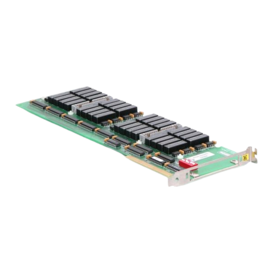
Keithley PIO-32OUT
32-Channel Relay Output Board
A l l t r a d e m a r k s , b r a n d n a m e s , a n d b r a n d s a p p e a r i n g h e r e i n a r e t h e p r o p e r t y o f t h e i r r e s p e c t i v e o w n e r s .
• C r i t i c a l a n d e x p e d i t e d s e r v i c e s
• I n s t o c k / R e a d y - t o - s h i p
Artisan Scientific Corporation dba Artisan Technology Group is not an affiliate, representative, or authorized distributor for any manufacturer listed herein.
In Stock
Used and in Excellent Condition
Buy Today!
https://www.artisantg.com/61736-1
• We b u y y o u r e x c e s s , u n d e r u t i l i z e d , a n d i d l e e q u i p me n t
• F u l l - s e r v i c e , i n d e p e n d e n t r e p a i r c e n t e r
Advertisement
Table of Contents
Troubleshooting

Related Manuals for Keithley PIO-32OUT


Summary of Contents for Keithley PIO-32OUT
- Page 1 Keithley PIO-32OUT 32-Channel Relay Output Board In Stock Used and in Excellent Condition Buy Today! https://www.artisantg.com/61736-1 A l l t r a d e m a r k s , b r a n d n a m e s , a n d b r a n d s a p p e a r i n g h e r e i n a r e t h e p r o p e r t y o f t h e i r r e s p e c t i v e o w n e r s .
- Page 2 PIO-32 Series User’s Guide A G R E A T E R M E A S U R E O F C O N F I D E N C E Artisan Technology Group - Quality Instrumentation ... Guaranteed | (888) 88-SOURCE | www.artisantg.com...
-
Page 3: Other Hardware
Hardware Keithley Instruments, Inc. warrants that, for a period of one (1) year from the date of shipment (3 years for Models 2000, 2001, 2002, 2010 and 2700), the Keithley Hardware product will be free from defects in materials or workmanship. This warranty will be honored provided the defect has not been caused by use of the Keithley Hardware not in accordance with the instructions for the product. -
Page 4: Disclaimer Of Warranties
EXCEPT FOR THE EXPRESS WARRANTIES ABOVE KEITHLEY DISCLAIMS ALL OTHER WARRANTIES, EXPRESS OR IMPLIED, INCLUDING WITHOUT LIMITATION, ALL IMPLIED WARRANTIES OF MERCHANT- ABILITY AND FITNESS FOR A PARTICULAR PURPOSE. KEITHLEY DISCLAIMS ALL WARRANTIES WITH RESPECT TO THE OTHER HARDWARE AND OTHER SOFTWARE. - Page 5 The information contained in this manual is believed to be accurate and reliable. However, Keithley Instruments, Inc., assumes no responsibility for its use; nor for any infringements or patents or other rights of third parties that may result from its use. No license is granted by implication or otherwise under any patent rights of Keithley Instruments, Inc.
- Page 6 PIO-32 Series User’s Guide Revision E - April, 2001 Part Number: 88170 Artisan Technology Group - Quality Instrumentation ... Guaranteed | (888) 88-SOURCE | www.artisantg.com...
-
Page 7: Safety Precautions
Keithley products are designed for use with electrical signals that are rated Installation Category I and Installation Category II, as described in the International Electrotechnical Commission (IEC) Standard IEC 60664. Most mea- surement, control, and data I/O signals are Installation Category I and must not be directly connected to mains voltage or to voltage sources with high transient over-voltages. - Page 8 (Note that selected parts should be purchased only through Keithley Instruments to maintain accuracy and functionality of the product.) If you are unsure about the applicability of a replacement component, call a Keithley Instruments office for information.
-
Page 9: Table Of Contents
Table of Contents Preface Overview Important Safety Instructions ......Supporting Software ....... . Accessories . - Page 10 Troubleshooting Problem Isolation ........Identifying Symptoms and Possible Causes ... Testing the PIO-32 Series Board and Host Computer .
- Page 11 PIO-32IN Register Map ....C-3 Table C-4 PIO-32OUT Register Map ....C-4 Artisan Technology Group - Quality Instrumentation ... Guaranteed | (888) 88-SOURCE | www.artisantg.com...
- Page 12 Artisan Technology Group - Quality Instrumentation ... Guaranteed | (888) 88-SOURCE | www.artisantg.com...
-
Page 13: Preface
Preface The PIO-32 Series User’s Guide explains how to install, cable, wire, program, and use the PIO-32 Series isolated, digital input and output (I/O) boards. This guide serves data acquisition system designers, engineers, technicians, programmers, scientists, and other users responsible for setting up, cabling, wiring, and programming the PIO-32 Series boards. - Page 14 Appendix B lists the connector pin assignments. Appendix C provides a register map, for background reference only (you program the PIO-32 Series boards through the DriverLINX interface, not at the register-level). An index completes this guide. Artisan Technology Group - Quality Instrumentation ... Guaranteed | (888) 88-SOURCE | www.artisantg.com...
-
Page 15: Overview
PIO-32I/O, which provides 16 digital inputs and 16 digital outputs PIO-32IN, which provides 32 digital inputs PIO-32OUT, which provides 32 digital outputs The major features of all PIO-32 Series boards include the following: Input level (if included) of 3.5VDC to 28VDC Output relay contacts (if included), Form A, 0.75A at 30V RMS,... -
Page 16: Important Safety Instructions
Important Safety Instructions Each PIO-32 Series board bears a warning symbol that corresponds to the information in this section. Follow these steps when preparing to install your PIO-32 board: 1. Read the warnings in this section. 2. When installing, cabling, and wiring your board, heed the warnings marked on the board and described in this section, and follow the instructions in Sections 3 and 4. -
Page 17: Supporting Software
Supporting Software DriverLINX software is supplied by Keithley with the PIO-32 Series board. DriverLINX provides convenient interfaces to configure and set I/O bits without register-level programming. Most importantly, however, DriverLINX supports those programmers who wish to create custom applications using Visual C/C++, Visual Basic, or Delphi. -
Page 18: Accessories
DriverLINX is essentially hardware independent, because its portable APIs work across various operating systems. This capability eliminates unnecessary programming when changing operating system platforms. Accessories The optional accessories for the PIO-32 Series boards include screw terminal panels (STPs) and cables (C-3200/C-32NN) that convert from the ribbon headers on the board to the 37-D male cable connectors. -
Page 19: Functional Description
Functional Description This section describes the general layout of the PIO-32 Series boards and provides schematics of the typical input and output circuits. The PIO-32 Series boards are channel-to-channel isolated and handle digital voltages in a broader range than standard TTL levels. Optional accessories for the board include screw terminal panels (STPs) and the C-3200 cables. -
Page 20: Input Circuitry
Input Circuitry The PIO-32I/O has 16 digital input channels and uses the J1 ribbon header (channels 0 to 15). The PIO-32IN has 32 digital input channels and uses the J1 and J2 ribbon headers (channels 0 to 31). Figure 2-2 shows each input channel schematically. -
Page 21: Output Circuitry
Output Circuitry The PIO-32I/O has 16 digital output channels and uses the J2 ribbon header (channels 16 to 31). The PIO-32OUT has 32 digital output channels and uses the J1 and J2 ribbon headers (channels 0 to 31). Figure 2-3 shows the output channels schematically. The output channels are reed relays (form A) rated to 10W at 0.75A or 30V RMS, 42.4V peak,... -
Page 22: Setup And Installation
Setup and Installation The procedures in this section are intended for qualified Warning: service personnel. Do not perform these procedures unless you are qualified to do so. Overview This section describes the following: Inventorying installation resources. Installing the DriverLINX software needed to operate your PIO-32 board. -
Page 23: Inventorying Required Installation Resources
Note: Install the DriverLINX software before installing the PIO-32 board. Otherwise, the device drivers will be more difficult to install. Inventorying Required Installation Resources Before installing DriverLINX and the board, do the following: 1. Inventory your PIO-32 board’s configuration settings. 2. -
Page 24: Installing Driverlinx Software And Documentation
Installing DriverLINX Software and Documentation Even if DriverLINX versions other than the PIO Series version are Note: already installed on your system, you must also install the PIO Series DriverLINX version. In the process, some DriverLINX capabilities shared by all boards may be upgraded (test utilities, for example). This section discusses installation of drivers, interfaces, and documentation. - Page 25 A star next to a menu item means that it was selected previously. Before continuing with this installation, Keithley suggests clicking Read Me First on the DriverLINX CD Navigator and reviewing the brief information that appears.
- Page 26 Configuration. c. Under Configuration click Hardware References. A list of documents appears. d. In the list of documents, click Keithley PIO Series. Acrobat Reader opens and the manual entitled Using DriverLINX with Your Hardware—Keithley PIO Series appears. e. Print the following section from the Using DriverLINX with Your Hardware—Keithley PIO Series manual: “Configuring the...
-
Page 27: Configuring Your Installation
Configuring Your Installation 1. Locate and briefly review the manual section, “Configuring the PIO Series,” that you printed earlier during step 9 of “Installing DriverLINX Software and Documentation.” Reviewing this section will help prepare you to input information and select options when configuring your installation. -
Page 28: Preparing And Installing Your Board
Preparing and Installing Your Board Ensure that the computer is turned OFF before installing or Caution: removing a board. Installing or removing a board while power is ON can damage your computer, the board, or both. Handle the board in a static-controlled workstation; wear a grounded wrist strap. -
Page 29: Setting The Base Address
Before setting the base address switches, check the different Note: requirements for Windows 95/98 and Windows NT. Refer to “Configuring the PIO Series” in Using DriverLINX with Your Hardware—Keithley PIO Series manual, which you printed in step 9 of “Installing the DriverLINX Software.”... -
Page 30: Installing The Board
60VDC to any input or output on this board. Live voltages can still be present on the board even when the computer is turned off. To protect you and the circuit, Keithley provides covers with the PIO-32 Series boards. Though you can remove the covers to service the PIO-32 Series boards, do not use these boards with the covers removed! In addition, disconnect all cables when servicing these boards. - Page 31 To install the board, perform the following steps: 1. Turn power to the computer and all attached equipment OFF. 2. Remove the computer chassis cover. 3. Select an available slot appropriate to the length of the board. 4. Loosen and remove the screw at the top of the blank adapter plate, and then slide the plate up and out to remove.
-
Page 32: Checking Your Installation
Checking Your Installation The ability to start the DriverLINX AIO Panel utility, which is available after you install DriverLINX, verifies that DriverLINX and the board are installed and configured satisfactorily. You can also test the functions of the PIO-32 board, without needing to write an application program, by connecting appropriate digital signals and observing the responses with the DriverLINX AIO Panel. -
Page 33: Figure 3-2 An Aio Panel Example
c. Click on the AIO Panel entry. The Analog I/O Panel should appear, similar to the example in Figure 3-2. (If you have other DriverLINX devices installed in addition to the digital input/output card you are testing, they will also be listed. In that case, select the desired digital I/O card and the proper device number before proceeding.) Figure 3-2. -
Page 34: Figure 3-3 Dio Channel Tab Example
2. On the AIO Control Panel, click the DIO tab. Figure 3-3. DIO channel tab example 3-13 Artisan Technology Group - Quality Instrumentation ... Guaranteed | (888) 88-SOURCE | www.artisantg.com... - Page 35 Note: The on-screen digital I/O controller works as follows: Channels 0 to 15 refer to the 8-bit general-purpose registers of your digital input-output card. (Depending on which card is used, the number of valid 8-bit registers will vary.) Bits displayed on the Digital Input Panel and the Digital Output Panel are numbered 0-7 for every channel.
- Page 36 3. Under Digital I/O Configuration Panel, configure channels as shown in Figure 3-4. (Actual channels available will vary according to your hardware.) KEITHLEY Digital I/O Configuration Panel Channel Configuration Input Output Figure 3-4. Configuring the digital I/O channels as inputs and outputs...
-
Page 37: Output Set Test
6. In the Digital Input Panel under Channels, click on a channel to select it and display the logical state of its input lines. Output Set Test The output set test checks whether logic levels measured at all output pins agree with output bit patterns set by software, using a DriverLINX graphical interface (AIO Panel). -
Page 38: Figure 3-6 An Aio Panel Example
6. Start the AIO Panel as follows: a. In the Start menu, click Programs. b. Find the DriverLINX ➧ Test Panels folder, under which you should find the AIO Panel entry. c. Click on the AIO Panel entry. The Analog I/O Panel should appear, similar to the example in Figure 3-6. - Page 39 “I/O Bit Tests” of this section. 8. Under Digital I/O Configuration Panel, configure the output channels to be tested as shown in Figure 3-7. (Actual output channels will vary according to your hardware.) KEITHLEY Digital I/O Configuration Panel Channel Configuration Input Output Figure 3-7.
- Page 40 9. In the Digital Output Panel under Channels, click on an output channel (channel 0 in this example) as shown in Figure 3-8. KEITHLEY Digital Output Panel Channels Output Bits Figure 3-8. Configuring channel 0 for output bit pattern A 10.
- Page 41 13. In the Digital Output Panel under Channels, click on the output channel to test (channel 0 in this example) as shown in Figure 3-9. KEITHLEY Digital Output Panel Channels Output Bits Figure 3-9. Configuring channel 0 for output bit pattern B 14.
-
Page 42: Input Read Test
If the bit patterns set on the AIO Panel do agree with the logic levels measured at the I/O terminals, and you have performed an output set test for all ports, the board is functioning properly. 17. Repeat steps 13, 14, and 15 for additional output channels. Input Read Test A similar test of input circuitry can be performed by applying an input signal of suitable type to each input line and verifying that the appropriate... -
Page 43: Cabling And Wiring
Cabling and Wiring The procedures in this section are intended for qualified Warning: service personnel. Do not perform these procedures unless you are qualified to do so. After installing your PIO-32 Series boards, you can attach accessories and wire the appropriate signals to the board. This section includes the following information about cabling and wiring the PIO-32 Series boards: Description and illustration of the optional C-3200/C-32NN cables for the PIO-32 Series boards... -
Page 44: Optional Cables
Optional Cables Do not use the C-3200/C-32NN cables at voltages above Warning: 30V RMS, 42.4V peak, or 60VDC. These cables are rated for 30V RMS, 42.4V peak, or 60VDC maximum. Use at higher voltages may result in insulation breakdown and shock hazard. To connect the PIO-32 Series boards to screw terminal panel accessories or other equipment, you need additional cables. -
Page 45: Stp-37/Fc Screw Terminal Panel
Figure 4-2. PIO-32 Series Board Cabled to Screw Terminal Panels Caution: Keithley recommends that you always use the STP-37/FC with a case and cover. Figure 4-3 shows the mounting holes for the STP-37/FC without the case. Artisan Technology Group - Quality Instrumentation ... Guaranteed | (888) 88-SOURCE | www.artisantg.com... -
Page 46: Figure 4-3 Stp-37/Fc Mounting Holes
4.79 in. 0.20 in. 4.400 in. 0.81 1.250 pin 1 mounting holes mounting holes (0.125 in. DIA) (0.125 in. DIA) 2.84 in. pin 1 for rubber feet (4 holes) Figure 4-3. STP-37/FC Mounting Holes Cabling and Wiring Artisan Technology Group - Quality Instrumentation ... Guaranteed | (888) 88-SOURCE | www.artisantg.com... -
Page 47: Typical Digital I/O Wiring
This section provides a typical non-TTL digital input wiring example for the PIO-32IN board and a typical digital output control wiring example for the PIO-32OUT board. In the digital input example shown in Figure 4-4, the PIO-32IN board monitors the presence of non-TTL signals. If no signal is present, the input value is 0;... -
Page 48: Figure 4-5 Typical Digital Output Control
In the digital output example shown in Figure 4-5, the PIO-32OUT board is used to control the on and off state of a device. The polarity does not matter in this example. LOAD Positive (+) Power PIO-32OUT Supply Negative (-) Figure 4-5. -
Page 49: Figure 4-6 Pin Assignments For The C-3200 Cable 37-D Connector, J1 Signals
37-D Cable Connector, J1 Signals Pin 19 Pin 37 Pin 18 Pin 36 Pin 17 Pin 35 Pin 16 Pin 34 Pin 15 Pin 33 Pin 14 Pin 32 Pin 13 Pin 31 Pin 12 Pin 30 P12N Pin 11 Pin 29 P11N P12P... -
Page 50: Figure 4-7 Pin Assignments For The C-3200 Cable 37-D Connector, J2 Signals
37-D Cable Connector, J2 Signals P16N Pin 19 Pin 37 P23N P16P Pin 18 Pin 36 P23P P17N Pin 17 Pin 35 P22N P17P Pin 16 Pin 34 P22P P18N Pin 15 Pin 33 P21N P18P Pin 14 Pin 32 P21P P19N Pin 13... -
Page 51: Figure 4-8 Pin Assignments For 40-Pin Ribbon Header
40-Pin Ribbon Header, J1 Signals Pin 40 Pin 39 Pin 38 Pin 37 Pin 36 Pin 35 Pin 34 Pin 33 Pin 32 Pin 31 Pin 30 Pin 29 Pin 28 Pin 27 Pin 25 Pin 26 Pin 23 Pin 24 P12N Pin 21 Pin 22... -
Page 52: Figure 4-9 Pin Assignments For The 40-Pin Ribbon Header
40-Pin Ribbon Header, J2 Signals Pin 39 Pin 40 P16N Pin 37 Pin 38 Pin 36 P23N P16P Pin 35 P17N Pin 33 Pin 34 P23P P17P Pin 31 Pin 32 P22N Pin 30 P22P P18N Pin 29 P18P Pin 27 Pin 28 P21N Pin 26... - Page 53 Programming You do not program the registers of your PIO-32 Series board directly through Windows 95/98/NT. Instead, you program register changes through the application programming interface (API) of DriverLINX. DriverLINX is provided on the CD-ROM that comes with your board and should now be installed on your system.
- Page 54 6. Click on the wanted document or document category. Either the selected document appears or a list of documents that fit the selected category appears. 7. If a list appears, click on the title of the document that you want. The desired document appears.
-
Page 55: Troubleshooting
If you encounter a problem with a PIO-32 Series board, use the instructions in this section to isolate the cause of the problem before calling Keithley Technical Support. Identifying Symptoms and Possible Causes Use the troubleshooting information in Table 6-1 to try to isolate the problem. -
Page 56: Table 6-1 Troubleshooting Information
The board is incorrectly aligned Check installation. in the accessory slot. The board is damaged. Contact the Keithley Applications Engineering Department; see page 6-6. Intermittent The most common cause of this Reduce I/O bus speed to a maximum of... - Page 57 Table 6-1. Troubleshooting Information (cont.) Symptom Possible Cause Possible Solution Data appears to be The most common cause of this Reduce I/O bus speed to a maximum of invalid problem is that the I/O bus speed 8 MHz (to change the I/O bus speed, run is in excess of 8 MHz.
-
Page 58: Testing The Pio-32 Series Board And Host Computer
60VDC to any input or output on this board. Live voltages can still be present on the board even when the computer is turned off. To protect you and the circuit, Keithley provides covers with the PIO-32 Series boards. Though you can remove the covers to service the PIO-32 Series boards, do not use these boards with the covers removed! In addition, disconnect all cables when servicing these boards. -
Page 59: Testing The Accessory Slot And I/O Connections
Testing the Accessory Slot and I/O Connections When you are sure that the computer is operating properly, test the computer accessory slot and I/O connections using another PIO-32 Series board that you know is functional. To test the computer accessory slot and the I/O connections, follow these steps: 1. -
Page 60: Technical Support
Technical Support Before returning any equipment for repair, call the Keithley Hardware Applications Engineering Department at: 1-888-KEITHLEY Monday - Friday, 8:00 a.m. - 5:00 p.m., Eastern Time An applications engineer will help you diagnose and resolve your problem over the telephone. Please make sure that you have the following... - Page 61 If you are submitting your equipment for repair under warranty, you must include the invoice number and date of purchase. To enable Keithley to respond as quickly as possible, you must include the RMA number on the outside of the package.
-
Page 62: Specifications
This appendix provides a table of the specifications for the PIO-32 Series boards. In Table A-1, the abbreviation N/A means not applicable. Table A-1. PIO-32 Series Specifications Feature Attribute PIO-32I/O PIO-32IN PIO-32OUT Digital Channels Output Contact Type Rhodium plated Rhodium plated (Form A, normally... - Page 63 Table A-1. PIO-32 Series Specifications (cont.) Feature Attribute PIO-32I/O PIO-32IN PIO-32OUT Digital Input Channels Type Optoisolator Optoisolator Input 2.0kΩ, 1/2W 2.0kΩ, 1/2W Resistor Input High 3.5VDC, 1.25mA 3.5VDC, 1.25mA (Min.) Input High 28VDC, 15mA 28VDC, 15mA (Max.) Input Low 0.8VDC or open 0.8VDC or open...
-
Page 64: Connector Pin Assignments
Connector Pin Assignments This appendix provides a table of the connector pin assignments for the 37-D and 40-pin ribbon connectors and of the signals for the J1 and J2 connectors of the PIO-32 Series boards. In addition, this appendix contains the same pin assignment figures for these connectors as shown in Section 4. -
Page 65: J2 Signals
Table B-1. 37-D and 40-Pin Signals for Connectors J1 and J2 37-D Ribbon PIO-32 J1 PIO-32 J2 37-D Ribbon PIO-32 J1 PIO-32 J2 Pins Pins Signals Signals Pins Pins Signals Signals GROUND GROUND P24P P15P P31P P24N P15N P31N P25P P14P P30P P25N... -
Page 66: Figure B-1 Pin Assignments For The C-3200 Cable 37-D
Figure B-1 shows the pin assignments for the 37-D cable connector, J1 signals. Figure B-2 on page B-4 shows the pin assignments for the 37-D cable connector, J2 signals. Figure B-3 on page B-5 shows the pin assignments for the 40-in ribbon header, J1 signals. Figure B-4 on page B-6 shows the pin assignments for the 40-pin ribbon header, J2 signals. -
Page 67: Figure B-2 Pin Assignments For The C-3200 Cable 37-D
C-3200 Cable 37-D Cable Connector, J2 Signals P16N Pin 19 Pin 37 P23N P16P Pin 18 Pin 36 P23P P17N Pin 17 Pin 35 P22N P17P Pin 16 Pin 34 P22P P18N Pin 15 Pin 33 P21N P18P Pin 14 Pin 32 P21P P19N... -
Page 68: Figure B-3 Pin Assignments For 40-Pin Ribbon Header
40-Pin Ribbon Header Connector, J1 Signals Pin 40 Pin 39 Pin 38 Pin 37 Pin 36 Pin 35 Pin 34 Pin 33 Pin 32 Pin 31 Pin 30 Pin 29 Pin 28 Pin 27 Pin 25 Pin 26 Pin 23 Pin 24 P12N Pin 21... -
Page 69: Figure B-4 Pin Assignments For 40-Pin Ribbon Header
40-Pin Ribbon Header Connector, J2 Signals Pin 39 Pin 40 P16N Pin 37 Pin 38 Pin 36 P23N P16P Pin 35 P17N Pin 33 Pin 34 P23P P17P Pin 31 Pin 32 P22N Pin 30 P22P P18N Pin 29 P18P Pin 27 Pin 28 P21N... -
Page 70: Register Maps
Register Maps Address maps are provided here only for background reference Note: purposes. You do not program registers directly in Windows 95/98/NT. Instead, you program register changes through the application programming interface (API) of DriverLINX, which is provided on the CD-ROM that comes with your board. -
Page 71: Table C-1 Pio-32 Series Register Map Summary
Table C-2 lists the register map for the PIO-32I/O board; Table C-3 lists the register map for the PIO-32IN board; and Table C-4 lists the register map for the PIO-32OUT board. In each table, the abbreviation BA is for the Base Address. -
Page 72: Table C-2 Pio-32I/O Register Map
Table C-2. PIO-32I/O Register Map BA Write Bits Read Bits Not Used Input Port +0h - Not Used Input Port +1h - P15 P14 P13 P12 P11 P10 P9 Output Port Readback Port +4h P23 P22 P21 P20 P19 P18 P17 P16 P23 P22 P21 P20 P19 P18 P17 P16 Output Port Readback Port +5h P31 P30 P29 P28 P27 P26 P25 P24 P31 P30 P29 P28 P27 P26 P25 P24... -
Page 73: Table C-4 Pio-32Out Register Map
Table C-4. PIO-32OUT Register Map BA Write Bits Read Bits Output Port Readback Port +0h P7 Output Port Readback Port +1h P15 P14 P13 P12 P11 P10 P9 P15 P14 P13 P12 P11 P10 P9 Output Port Readback Port +4h P23 P22 P21 P20 P19 P18 P17 P16 P23 P22 P21 P20 P19 P18 P17 P16... -
Page 74: Programming
Numerics connecting a screw terminal panel connections 37-D cable connector, J2 signals connector pin assignments 4-6, 40-pin ribbon header, J1 signals connectors 40-pin ribbon header, J2 signals 4-10, covers for boards 1-2, 3-9, 40-pin ribbon header/cable connector, J1 signals 8255 Programmable Peripheral Interface integrated circuit default base address digital input... - Page 75 DriverLINX PIO-32IN interfaces features installing for applications input circuitry register map specifications PIO-32OUT features layout, general output circuitry register map specifications precautions, installation board Manuals, DriverLINX DriverLINX before board accessing problem isolation manuals, DriverLINX...
- Page 76 specifications STP See screw terminal panel registers STP-37/FC screw terminal panel 1-4, maps supporting software programming switch block, base address relay connections resources, installation, inventory returning equipment RMA number routing signals technical support 37-D cable connector, J1 signals 37-D cable connector, J2 signals troubleshooting typical digital I/O wiring safety instructions...
- Page 77 Specifications are subject to change without notice. All Keithley trademarks and trade names are the property of Keithley Instruments, Inc. All other trademarks and trade names are the property of their respective companies. Keithley Instruments, Inc. 28775 Aurora Road • Cleveland, Ohio 44139 • 440-248-0400 • Fax: 440-248-6168 1-888-KEITHLEY (534-8453) •...
Need help?
Do you have a question about the PIO-32OUT and is the answer not in the manual?
Questions and answers