Table of Contents
Advertisement
Quick Links
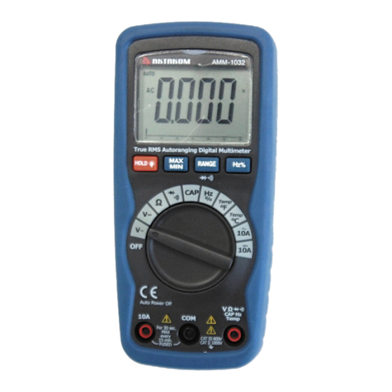
True RMS
AUTORANGING MULTIMETER
AMM-1032
User's Manual
http://www.tmatlantic.com
SAFETY INFORMATION
The following safety information must be observed to
insure maximum personal safety during the operation
at this meter:
Do not use the meter if the meter or test leads
look damaged, or if you suspect that the meter is
not operating properly.
Never ground yourself when taking electrical
measurements. Do not touch exposed metal pipes,
outlets, fixtures, etc., which might be at ground
potential. Keep your body isolated from ground
by using dry clothing, rubber shoes, rubber mats,
or any approved insulating material.
Turn off power to the circuit under test before
cutting, unsoldering, or breaking the circuit.
Small amounts of current can be dangerous.
Use caution when working above 60V dc or 30V
ac rms. such voltages pose a shock hazard.
When using the probes, keep your fingers behind
the finger guards on the probes.
Measuring voltage which exceeds the limits of
the multimeter may damage the meter and
expose the operator to a shock hazard. Always
recognize the meter voltage limits as stated on
the front of the meter.
Never apply voltage or current to the meter that
exceeds the specified maximum:
Input Limits
Function
V DC or V AC
A DC/AC
Frequency,
Resistance,
Capacitance, Cycle,
Diode
test,
Continuity
Temperature
SAFETY SYMBOLS
This symbol adjacent to another
symbol, terminal or operating device
indicates that the operator must refer
to an explanation in the Operating
Instructions to avoid personal injury
or damage to the meter.
WARNING
This WARNING symbol indicates a
potentially hazardous situation, which
if not avoided, could result in death or
serious injury.
CAUTION
This CAUTION symbol indicates a
potentially hazardous situation, which
if not avoided, may result damage to
the product.
MAX
This symbol advises the user that the
terminal(s) so marked must not be
connected to a circuit point at which
the voltage with respect to earth
ground exceeds (in this case) 500 VAC
Maximum Input
1000VDC/VAC
10A DC/AC (30
seconds max every
15 minutes)
600V DC/AC
600V DC/AC
Advertisement
Table of Contents

Related Manuals for Aktakom AMM-1032


Summary of Contents for Aktakom AMM-1032
- Page 1 Measuring voltage which exceeds the limits of AUTORANGING MULTIMETER the multimeter may damage the meter and AMM-1032 expose the operator to a shock hazard. Always User’s Manual recognize the meter voltage limits as stated on the front of the meter.
- Page 2 SYMBOLS AND ANNUNCIATORS or VDC. Continuity This symbol adjacent to one or more Low Battery terminals identifies them as being associated with ranges that may, in Diode normal use, subjected HOLD Data Hold particularly hazardous voltages. For AUTO AutoRanging maximum safety, the meter and its test Alternating Current or Voltage leads should not be handled when Direct Current or Voltage...
- Page 3 Capacitance (Auto-ranging) Range Resolution Accuracy 40.00nF 10pF +5.0% of rdg + 50 dgts 400.0nF 0.1nF +3.0% of rdg + 5 dgts 4.000uF 40.00uF 10nF Accuracy is given at 18 o C to 28 o C (65 o F to 83 o F), 400.0uF 0.1uF +5.0% of rdg + 5 dgts...
- Page 4 has Auto OFF that automatically shuts the meter “min” occurs. OFF if 15 minutes elapse between uses. 3. To exit MAX/MIN mode press and hold the If “OL” appears in the display during a MAX/MIN key for 2 seconds measurement, the value exceeds the range you have DISPLAY BACKLIGHT selected.
- Page 5 AC CURRENT MEASUREMENTS AC VOLTAGE MEASUREMENTS WARNING: To avoid electric shock, do not measure WARNING: Risk of Electrocution. The probe tips AC current on any circuit whose voltage exceeds 250V may not be long enough to contact the live parts inside some 240V outlets for appliances because the contacts are recessed deep in the outlets.
- Page 6 RESISTANCE MEASUREMENTS 5. Reverse the probe polarity by switching probe position. WARNING: To avoid electric shock, disconnect power Note this reading. to the unit under test and discharge all capacitors before 6. The diode or junction can be evaluated as follows: taking any resistance measurements.
- Page 7 TEMPERATURE MEASUREMENTS 2. Open the battery door by loosening the screw using a Phillips head screwdriver. WARNING: To avoid electric shock, disconnect both 3. Insert the battery into battery holder, observing the test probes from any source of voltage before making a correct polarity.
Need help?
Do you have a question about the AMM-1032 and is the answer not in the manual?
Questions and answers