Table of Contents
Advertisement
Com. no.
..................................................
Operator
............................................................................................................................................................
Operating place ........................................................................................................................................................
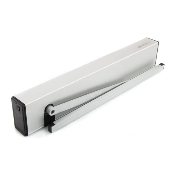
Swing door drive mechanism
FD 10
Mounting and operating instructions
Pos.
0549-990/02a
Original
.................................
2019.11
Construction year ...................
Advertisement
Table of Contents

Related Manuals for GILGEN FD 10


Summary of Contents for GILGEN FD 10
- Page 1 Swing door drive mechanism FD 10 Mounting and operating instructions Original Com. no........... Pos........Construction year ....Operator ................................Operating place ................................ 0549-990/02a 2019.11...
-
Page 2: Table Of Contents
FD 10 Mounting and operating instructions TABLE OF CONTENTS GENERAL REMARKS ........................ 4 Target group ........................4 Adresses ......................... 4 Auxiliary tools and service performances ..............5 SAFETY ............................6 Appropriate use ......................6 Safety notices ......................... 6 Safety regulations ......................6 2.3.1... - Page 3 FD 10 Mounting and operating instructions 7.4.3 Glass sticker ....................45 7.4.4 Rating plate ....................45 Mount the drive mechanism covering ................. 46 SERVICE ..........................47 Service for pedestrian doors ..................48 Fundamental checking ....................49 TROUBLESHOOTING ......................50 Malfunction with error-no................... 50 9.1.1...
-
Page 4: General Remarks
Only the trained experts of the manufacturer or the supplier are counted among these persons. Adresses Distribution agent/ After-sales service Manufacturer Gilgen Door Systems AG Freiburgstrasse 34 CH-3150 Schwarzenburg Phone +41 31 734 41 11 +41 31 734 43 79 www.gilgendoorsystems.com... -
Page 5: Auxiliary Tools And Service Performances
FD 10 Mounting and operating instructions Auxiliary tools and service performances The auxiliary tools and service performances listed hereafter are available, depending on the respective situation and authorization (please ask your distribution agent): • Company portrait • Homepage • E-shop (authorization) •... -
Page 6: Safety
SAFETY Appropriate use The swing door drive mechanism FD 10 has been exclusively designed for operating swing doors. Any other use beyond these application limits is deemed inappropriate and inadmissible! In the event of an inappropriate use of this system, the safety of the user may be jeopar dized and/or the installation be damaged. - Page 7 • In its assembled state, the installation must answer all the safety requirements specified by the machinery directive. • The swing door drive mechanism FD 10 may only be installed and operated in dry rooms. If this condition cannot be fulfilled, the customer must provide sufficient protection from moisture.
-
Page 8: Service
A safe and reliable function of the installation can only be guaranteed if it is operated with the original Gilgen Door Systems accessories/spare parts. Gilgen Door Systems declines all responsi- bility for damages resulting from unauthorized modifications of the installation or from the use of foreign accessories/spare parts. -
Page 9: Product Description
FD 10 Mounting and operating instructions PRODUCT DESCRIPTION General remarks The swing door drive mechanism FD 10 opens and closes the door leaf via a rod assembly (is not shown in the illustration). Drive mechanism Drive mechanism covering Side cover... -
Page 10: Standard Application
FD 10 Mounting and operating instructions Normal rods Sliding rods A Rotating arm B Fixing screw C Rod arm D Door connection angle E Sliding rail F Glider 3.2 Standard application During normal operation, the opening and closing movements of the door leaf are motorized. -
Page 11: Automatic Closing Sequence Control
FD 10 Mounting and operating instructions 3.3 Automatic closing sequence control For bi-parting installations, two separate FD 10 swing door drive mechanisms are used, which are connected via connection terminals. Drive mechanism 1 Master Drive mechanism 2 Slave Earlier door leaf the first one to open... -
Page 12: Technical Data
FD 10 Mounting and operating instructions Technical data Drive mechanism Standard Power transmission Normal rods Sliding rods Dimensions drive mechanism Height 70 mm Width 730 mm Depth 125 mm Weight drive mechanism 8,2 kg Ambient temperature -15...+50 °C May only be used in dry rooms max. -
Page 13: Mounting
FD 10 Mounting and operating instructions MOUNTING General Attention: It is recommended that a door leaf stop piece be mounted by the customer. This stop piece prevents the door leaf from being damaged in the manual operating mode. Attention: Check the free running movement of the door leaf. Should it fail to move smoothly and silently, or if it is out of balance (i. - Page 14 FD 10 Mounting and operating instructions DIN left DIN right Normal rods RS 0548-163 pushing function Normal rods RS 0548-163 pushing function Lintel mounting see chapter 4.4 Lintel mounting see chapter 4.4 Lintel depth 0...250 mm Lintel depth 0...250 mm Drive mechanism...
-
Page 15: Drive Mechanism
FD 10 Mounting and operating instructions Drive mechanism Mark and drill fixing holes in the lintel/door leaf in accordance with the situation. Note: You can use the chassis profile (B) as a drilling template. Observe the alignment of the chassis profile (B). - Page 16 FD 10 Mounting and operating instructions For normal rods RS and sliding rods RG pushing function: Hang the drive module, with the PUSH sign facing the chassis profile (B), onto the two pre-inserted screws (C). Adjust the position of the control unit (E) before pro- ceeding.
-
Page 17: Normal Rods Rs Pushing Function / Lintel Mounting
FD 10 Mounting and operating instructions 4.4 Normal rods RS pushing function / Lintel mounting Material: Drive mechanism 0549-010 Covering aluminium Drive mechanism 0549-011 Covering inox incl. fixing set 0549-104 Normal rods RS 0548-163 Procedure: Mark out/drill the fastening holes on the lintel/door leaf and mount the drive mechanism. - Page 18 FD 10 Mounting and operating instructions Close the door leaf. Separate the rotating arm (C) from the rod arm (B) by loosen the screw (E). Fasten the rod arm (B) by means of the door connection angle (A) onto the door leaf.
-
Page 19: Sliding Rods Rg Pushing Function / Lintel Mounting
FD 10 Mounting and operating instructions 4.5 Sliding rods RG pushing function / Lintel mounting Material: Drive mechanism 0549-010 Covering aluminium Drive mechanism 0549-011 Covering inox incl. fixing set 0549-104 Sliding rods RG 0548-164 650 mm incl. sliding bolts 18/46 mm Procedure: Mark out/drill the fastening holes on the lintel/door leaf and mount the drive mechanism. - Page 20 FD 10 Mounting and operating instructions Close the door leaf. Screw down the rotating arm (D) on the drive unit Tightening moment 25 Nm. Attention: The pre-stressing of the rotating arm (D) depends on the existing lintel depth. Example: Lintel depth 0 mm, pre-stressing of the rotating arm (D) ≈ 15° (1 grid increment of the output shaft = 15°).
-
Page 21: Sliding Rods Rg Pulling Function / Lintel Mounting
FD 10 Mounting and operating instructions 4.6 Sliding rods RG pulling function / Lintel mounting Material: Drive mechanism 0549-010 Covering aluminium Drive mechanism 0549-011 Covering inox incl. fixing set 0549-104 Sliding rods RG 0548-164 650 mm incl. sliding bolts 18/46 mm Procedure: Mark out/drill the fastening holes on the lintel/door leaf. - Page 22 FD 10 Mounting and operating instructions Close the door leaf. Prior to the installation of the drive unit: Screw down the rotating arm (D) on the drive unit Tightening moment 25 Nm. Attention: The pre-stressing of the rotating arm (D) depends on the existing lintel depth.
-
Page 23: Adjusting The Internal Open Position Stop Piece
FD 10 Mounting and operating instructions 4.7 Adjusting the internal open position stop piece Procedure: Loosen (but do not remove) the three screws (A) on the open position stop piece (B). Note: If the open position stop piece (B) sticks, gently tap the screw heads to loosen it. -
Page 24: Adjusting The Pre-Stressing Of The Closing Spring
FD 10 Mounting and operating instructions Adjusting the pre-stressing of the closing spring Upon delivery, the closing spring (B) is pre-stressed for a measure X = 300 mm. In exceptional cases, the spring tension (setting X) may be set to between 300 mm and a maximum of 267 mm (without the pre-fitted rod assembly). -
Page 25: Setting The Accelerating Function (Forceful Closing)
FD 10 Mounting and operating instructions Setting the accelerating function (forceful closing) While an installation is in the state “without mains power” or in the operating mode MANUAL, the motor acts as an attenuator, thus guaranteeing a constant closing speed until the Closed posi- tion is reached. -
Page 26: Electrical Connections
FD 10 Mounting and operating instructions ELECTRICAL CONNECTIONS Power supply Warning: Electric shock hazard! Before working on the drive mechanism, completely disconnect the local mains power supply and block it to prevent accidental or unauthorised reac- tivation. Ensure also that country-specific regulations are observed. The mains power supply must meet the following requirements: 230 VAC (+10/-15 %), 50 Hz, 10/13 A. - Page 27 FD 10 Mounting and operating instructions Attach both side covers (C) to the chassis profile (G). Note: Depending on the assembly situation, it may be advisable to install the program selec- tor switch on the opposite side. pushing function pulling function...
-
Page 28: Cable Layout
FD 10 Mounting and operating instructions 5.2 Cable layout 5.2.1 Lintel mounting Be sure to run the cable between the drive module and the chassis profile wherever possible! 0549-990/02a 0549-990-01---10a_2019.11.indd Page 28 of 69... -
Page 29: External Elements
FD 10 Mounting and operating instructions External elements Mount all the required control and safety elements at their respective place. Lead the cables of the elements up to the drive mechanism (by customers). Connect the cables according to the diagram E4-0141-724 (in the appendix). -
Page 30: Control
FD 10 Mounting and operating instructions CONTROL Program selector switch The drive mechanism is supplied with a built-in program selector switch (A), which allows ena- bling the operating modes AUTOMATIC, OPEN and MANUAL. 6.2 Operating modes The following operating modes can be enabled by means of the program selec-... -
Page 31: Commissioning
FD 10 Mounting and operating instructions COMMISSIONING Warning: During the setting-up procedure (which must only be carried out by experts), the safety devices (radar, sensors, ...) are switched off! Before initiating the setting-up procedure, it is important to make sure that neither... - Page 32 FD 10 Mounting and operating instructions Adjust the opening speed Vo and validate by means of OK. Adjust the closing speed Vc and validate by means of OK. not yet available If desired: Invers Program the inverse application (spring-powered opening) and vali- date it by pressing OK.
-
Page 33: Adjustings
FD 10 Mounting and operating instructions 7.1 Adjustings The parameters can be changed on the control unit by means of the display and the joystick. 7.1.1 Motional parameters (PARAMETER) Parameter Description Setting range Default Opening speed (velocity open) 0...14 (5...40°/s) Closing speed (velocity close) 0...14... -
Page 34: Configuration (Config)
FD 10 Mounting and operating instructions 7.1.2 Configuration (CONFIG) Parameter Description Setting range Default Servo Support for manual push to open. The key opens automatically. Five-position adjustment, depending on the width and weight of the door leaf. 1...5 APuGo Triggering angle Push&Go (angle push&go) OFF, 2...10°... - Page 35 FD 10 Mounting and operating instructions MovCon Endurance test Open/Close (moving continuous) ON-FLT ON-PRM OExMAN Acceptance of opening commands after a manual door opening (only if APuGo = OFF) (opening element inside/outside manual) OEOSIR Safety device on opposite side to door hinge as opening element.
-
Page 36: Installations With Multiple Door Leaves (Double Door)
FD 10 Mounting and operating instructions 7.1.3 Installations with multiple door leaves (DOUBLE DOOR) Parameter Description Setting range Default DubleD Closing sequence role (Master/Slave) and interlock side (A/B) MastrA SlaveA BastrB SlaveB AoSeq Current delay angle for opening sequence control (Slave) 0...110° 20° (only visible if DubleD is active) -
Page 37: Menu Navigation
FD 10 Mounting and operating instructions 7.1.4 Menu navigation 0549-990/02a 0549-990-01---10a_2019.11.indd Page 37 of 69... - Page 38 FD 10 Mounting and operating instructions On the 1st level, the following information is shown on the display: 1st display line: The door position is represented by means of the arrows (><). Alternatively, the motion-relevant opening and safety signals are displayed. The double hash signs (##) indicate that the door is locked.
- Page 39 FD 10 Mounting and operating instructions DIAGNOSTICS Diagnostic tools • K-I-O-R-S-E shows the inputs KEY (K), OEI (I), OEO (O), SER (R), SES (S), EMY (E). (+) stands for active, (-) for inactive. • 5.1A 95° shows the motor current and the door opening angle.
- Page 40 FD 10 Mounting and operating instructions BLOCK/UNBLOC Lock/unlock the joystick • BLOCK Lock the joystick. For a temporary unlocking, press OK for more than 1 second. 60 seconds after the last joystick actuation, the joystick is automatically relocked. • UNBLOC Permanent unlocking of the joystick.
-
Page 41: Closing Sequence Control
FD 10 Mounting and operating instructions 7.2 Closing sequence control For bi-parting installations, the closing sequence control determines the order in which the door leaves are opened and closed. For the opening procedure, the earlier door leaf (Master leaf) is the first one to be opened, whereas for the closing procedure the delayed door leaf (Slave leaf) is the first one to be closed. - Page 42 FD 10 Mounting and operating instructions Function: The first door leaf to be put in motion for the opening procedure is the Master; by means of DubleD, this leaf is configured as MastrA. Its partner is the Slave, which is configured as SlaveA by means of DubleD.
- Page 43 FD 10 Mounting and operating instructions Procedure: Connect both control units by means of the three-pole cable (terminal X109, CG/CL/CH). Note: The respective control and safety elements are connected to the corresponding drive mechanism. Take the Master drive mechanism into operation (see chapter 7).
-
Page 44: Interlock Operation
FD 10 Mounting and operating instructions 7.3 Interlock operation Procedure: Note: Both installations must be plugged Exterior side into resp. out of the same power supply. Side A Connect both control units by means of the three-pole cable (terminal X109, CG/CL/ CH). -
Page 45: Adhesive Labels
29.04.13 kea Ohne sep. Stückliste 129 × 54 mm Anlage SLP - Redundant Auftrag © Gilgen Door Systems AG, CH-3150 Schwarzenburg Sep. Stückliste gleicher Nr. 2 Ohne sep. Stückliste Attach the rating plate (outside) onto the Anlage Auftrag Sep. Stückliste anderer Nr. 3 Sep. -
Page 46: Mount The Drive Mechanism Covering
0610-503 Set 0549-997/01 Procedure: Attach the Gilgen Logo: a) Degrease the gluing surface on the covering. b) Remove the white cover sheeting of the sticker (D). c) Position the template (B) with the logo (C) in the lower right-hand corner of the covering and tightly press on the logo (C). -
Page 47: Service
FD 10 Mounting and operating instructions SERVICE A regular service (maintenance/checking) is absolutely indispensable in order to guarantee a safe operation and long lifetime of the installation. The service must be carried out by a expert, at least once a year, according to the following checklist. -
Page 48: Service For Pedestrian Doors
Rating plate, arrow sticker, glass sticker, etc. existing? Control booklet existing and completed? Only for redundant drive mechanisms. Gilgen cleans all the elements of the installation provided this is necessary for the function of the installation. A general cleaning of the installation is not planned. 0549-990/02a 0549-990-01---10a_2019.11.indd... -
Page 49: Fundamental Checking
FD 10 Mounting and operating instructions Fundamental checking Warning: Electrocution hazard! Before working on any live elements, pull out the mains plug respectively switch off the main installation switch! Dismount the covering of the drive mecha- nism. Check all the cable connections. -
Page 50: Troubleshooting
FD 10 Mounting and operating instructions TROUBLESHOOTING Warning: Electric shock hazard! Before working on any live elements, pull out the mains plug respectively switch off the main installation switch! If a malfunction occurs which might be detrimental to the safety of the users, and which cannot be eliminated without delay, the operator must be informed and if requi- red the installation shall be taken out of operation. -
Page 51: Drive Mechanism
FD 10 Mounting and operating instructions 9.1.1 Drive mechanism Description Cause Elimination Checking time Reaction 03 Encoder Channels A + B lost Check the encoder connection. During run. Check the motor cable. Short-circuit A + B The door is blocked. -
Page 52: Safety Elements
FD 10 Mounting and operating instructions 9.1.3 Safety elements Description Cause Elimination Checking time Reaction E20 01 SER Test SER Test signal unsuccessful. SER short-circuit to the earth. Prior to closing. Check the cabling of the sensor or the jumper. -
Page 53: Malfunction Without Error-No
FD 10 Mounting and operating instructions 9.2 Malfunction without error-no. In some cases, it will be technically impossible to display an "irregular functioning" of the instal- lation by a definite error number. An alleged error may by all means also be due to "correct" cau- ses. -
Page 54: Software Update Via Usb
Mounting and operating instructions 9.3 Software update via USB A software update of the FD 10 control unit can be easily and rapidly achieved by means of an USB memory stick. Note: Not all the USB memory sticks can be used. We thus recommend a previous testing of their function together with the FD 10. -
Page 55: Procedure
FD 10 Mounting and operating instructions 9.3.2 Procedure FD 10 plug in the mains plug. Plug the USB stick into the control unit socket X111. update Go to UPDATE SW in the menu and press the joystick once. -
Page 56: Shut-Down
FD 10 Mounting and operating instructions SHUT-DOWN No particular measures need to be taken for de-commissioning the installation. If the swing door drive mechanism will not be used during at least 1 month, it is recommended to pull out the mains plug. -
Page 57: Spare Parts
FD 10 Mounting and operating instructions SPARE PARTS Article No. Designation Remark 0549-110 Drive module complete 0549-104 Fixing set 0549-206 Relay PCB Option 0635-142 D-BEDIX Option 0548-133 Service D-BEDIX for fitter 0549-326 Drive mechanism covering Aluminium 0549-105 Covering accessories Aluminium 0549-311... -
Page 58: Options
The D-BEDIX is connected to the control unit FD 10 via a screened two-core connection cable (e.g. U72M or EIB-Y(St)Y, max. length 50 m). Only one D-BEDIX can be connected per door installation. -
Page 59: Operating Modes
FD 10 Mounting and operating instructions 13.1.3 Operating modes With the D-BEDIX, the following operating modes can be selected by means of the corresponding symbols: AUTOMATIC Automatic operation. The installation can be locked. NIGHT The installation is locked . As opening commands, only the key-operated impulse switch is accepted. -
Page 60: Menu Level
FD 10 Mounting and operating instructions 13.1.5 Menu level Short and simultaneous actuation of both arrow keys (=access to the menu level). Select the desired menu item bymeans of the arrow key. Confirm by means of the OK key. Display... -
Page 61: Setting Examples
FD 10 Mounting and operating instructions 13.1.6 Setting examples Changing the operating mode Select the desired symbol by means of the arrow key (symbol starts flashing). Confirm with the OK key (frame/bar switch over). Preselecting the operating mode An overriding switch is active and determines the operating mode (only the selection frame is visible, the bar underlines the preselected operating mode). -
Page 62: Error Display
FD 10 Mounting and operating instructions Parameters (hold-open timeday) Short simultaneous actuation of the arrow keys (= access to the menu level). By means of the arrow key, select TOEx. Confirm with the OK key. By means of the arrow key, change the value. -
Page 63: Kombi-D-Bedix
FD 10 Mounting and operating instructions 13.2 KOMBI-D-BEDIX In addition to the functions of the D-BEDIX, the KOMBI-D-BEDIX contains a key-operated switch (round or profile cylinder) with the following function: Lockout of the KOMBI-D-BEDIX against unautho- rized use. Free Locked... -
Page 64: Connection Plate For Wooden Door Leaf (Normal Rods)
FD 10 Mounting and operating instructions 13.3 Connection plate for wooden door leaf (normal rods) The connection plate is mounted below the door connection angle of the normal rod assembly and screwed down by means of countersunk chipboard screws 5 x 30. Packing unit 0549-115 Connection plate... -
Page 65: Continuous Covering
FD 10 Mounting and operating instructions 13.4 Continuous covering For bi-parting installations, the two drive mechanisms can be optically connected by inserting an intermediate covering piece. Set with drive mechanism covering 0,78 m Alu 0549-210 Set with drive mechanism covering 0,78 m Inox... -
Page 66: Optional Pcbs
FD 10 Mounting and operating instructions 13.5 Optional PCBs All the optional PCBs are plugged into the control unit via a universal connector. A maximum number of two optional PCBs can be combined. Attention: All optional PCBs must only be plugged into/removed from the control unit after the dive unit has been disconnected from the power supply source! 13.5.1... -
Page 67: Safety Sensors
FD 10 Mounting and operating instructions 13.6 Safety sensors Safety sensors are fitted to automated swing doors to monitor and protect their pivoting area. They are fitted to both sides of the door leaf. This guarantees maximum protection during both opening and closing of the door. -
Page 68: Lzr-Flatscan
FD 10 Mounting and operating instructions 13.6.1 LZR-FLATSCAN In the event of swing doors, the FLATSCAN is mounted on the moving leaf, on the upper leaf cor- ners (as close as possible to the secondary closing edge). The FLATSCAN can only be used in pairs! Master and Slave are connected among each other (see wiring diagram in the appendix). -
Page 69: Appendix
FD 10 Mounting and operating instructions APPENDIX The following documents are added as an appendix to this instructions: Wiring diagram .......................E4-0141-724 0549-990/02a 0549-990-01---10a_2019.11.indd Page 69 of 69...
Need help?
Do you have a question about the FD 10 and is the answer not in the manual?
Questions and answers