Table of Contents
Advertisement
Quick Links
SMARTMAC 200 W
SMARTMAC 200 W
SMARTMAC 200 W
SMARTMAC 200 W
Display and operating unit for
SMARTPAT PH/ORP/COND sensors
Intrinsically safe
Equipment protection level Gb
Ex ia IIC T4
© KROHNE 09/2017 - 4005599202 - AD Ex SMARTMAC 200 en R02
Supplementary Instructions
Supplementary Instructions
Supplementary Instructions
Supplementary Instructions
Advertisement
Table of Contents

Related Manuals for KROHNE SMARTMAC 200 W


Summary of Contents for KROHNE SMARTMAC 200 W
- Page 1 SMARTMAC 200 W Supplementary Instructions Supplementary Instructions Supplementary Instructions Supplementary Instructions Display and operating unit for SMARTPAT PH/ORP/COND sensors Intrinsically safe Equipment protection level Gb Ex ia IIC T4 © KROHNE 09/2017 - 4005599202 - AD Ex SMARTMAC 200 en R02...
-
Page 2: Table Of Contents
1.4 Approval according to North-America standards ............4 1.5 Safety instructions......................4 2 Device description 2.1 Device description ......................5 2.2 Marking SMARTMAC 200 W....................6 2.3 Approval for zone classified locations ................7 2.4 Approval for division classified locations................. 8 2.5 Temperature classes......................8 2.6 Electrical data........................ -
Page 3: Safety Instructions
SAFETY INSTRUCTIONS SMARTMAC 200 W 1.1 General notes These supplementary instructions apply to versions of the loop powered display and operating unit for use in hazardous areas that fall in intrinsically safe protection type "i", equipment category II 2 G or EPL Gb. It complements the standard documentation for versions for use in non-hazardous areas. -
Page 4: Approval According To North-America Standards
SAFETY INSTRUCTIONS SMARTMAC 200 W 1.4 Approval according to North-America standards Equipment testing through QPS certifies that the equipment complies with applicable CSA and ANSI/ISA standards. The product is eligible to bear the QPS mark shown with adjacent indicators "C" and "US" for Canada and the USA. The number of the QPS certificate is: QPS LR1322-6. -
Page 5: Device Description
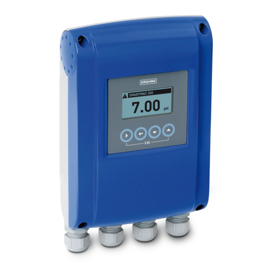
DEVICE DESCRIPTION SMARTMAC 200 W 2.1 Device description The loop powered display and operating unit is not only used to display measurements values on site but also to configure and calibrate sensors. Figure 2-1: Device description (left - die-cast aluminium / right - stainless steel) -
Page 6: Marking Smartmac 200 W
DEVICE DESCRIPTION SMARTMAC 200 W 2.2 Marking SMARTMAC 200 W 20...30 VDC IP66/67 NEMA 4/4X Figure 2-2: Example of a nameplate on the indicator body 1 Manufacturer 2 Device name 3 CE marking 4 Ex marking 5 China RoHS, Data matrix code (serial number),... -
Page 7: Approval For Zone Classified Locations
DEVICE DESCRIPTION SMARTMAC 200 W 2.3 Approval for zone classified locations The device meets the requirements of IEC 60079-11 for protection type "Intrinsic Safety". Explosion protection is ensured by limiting the current and voltage so that no ignitable energy can occur. The equipment protection level (EPL) Gb enables use in areas classified as Zone 1...Zone 2. -
Page 8: Approval For Division Classified Locations
DEVICE DESCRIPTION SMARTMAC 200 W 2.4 Approval for division classified locations In type of protection "Intrinsic Safety" the device meets the requirements of Canadian and US standards for the Division concept according to NEC 500. The explosion protection is ensured by limitation of the current and voltage so that no ignitable energy can occur. -
Page 9: Electrical Data
DEVICE DESCRIPTION SMARTMAC 200 W 2.6 Electrical data Connect the device only to intrinsically-safe certified circuits. Observe the following maximum values for the display when connecting: • U = 30 V • I = 120 mA • P = 1 W •... -
Page 10: Installation
INSTALLATION SMARTMAC 200 W 3.1 Installation DANGER! Installation and setup must be carried out according to the applicable installation standards (e.g. EN 60079-14) by qualified personnel trained in explosion protection. Observe the information contained in the manuals and the supplementary instructions. The installation must always comply with the following requirements: •... -
Page 11: Electrical Connections
ELECTRICAL CONNECTIONS SMARTMAC 200 W 4.1 General notes The intrinsically safe equipment is electrically connected in the display and operating unit. The circuit is designed in protection type "intrinsically safe" and galvanically isolated from ground (test voltage ≥ 500 V In order to avoid risks, always observe the following points when electrically connecting a device: •... -
Page 12: Power Supply
Figure 4-1: Overview terminal connections 4...20 mA input for Ex-approved device. 1 I.S. certified barrier, power supply 2 Current output signal 4...20 mA 3 Terminal connectors SMARTMAC 200 W 4 I.S. certified sensor powered display and operating unit and sensor are to be connected. -
Page 13: Grounding And Equipotential Bonding
ELECTRICAL CONNECTIONS SMARTMAC 200 W 4.3 Grounding and equipotential bonding If the device is not sufficiently electrostatically grounded via mounting, a ground connection must be established using the ground terminal 1. The position of the ground terminal is illustrated below. -
Page 14: Operation
OPERATION SMARTMAC 200 W 5.1 Start-up Start-up may only occur when the display and operating unit: • is correctly installed in the system and connected. • has been checked for the proper state with regard to its installation and connection requirements. -
Page 15: Service
SERVICE SMARTMAC 200 W 6.1 Maintenance Maintenance work of a safety-relevant nature within the meaning of explosion protection may only be carried out by the manufacturer, his authorised representative or under the supervision of authorised inspectors. For systems in hazardous areas, regular checks are required in order to maintain the proper condition. - Page 16 • Process Analysis • Services Head Office KROHNE Messtechnik GmbH Ludwig-Krohne-Str. 5 47058 Duisburg (Germany) Tel.: +49 203 301 0 Fax: +49 203 301 10389 info@krohne.com The current list of all KROHNE contacts and addresses can be found at: www.krohne.com...
Need help?
Do you have a question about the SMARTMAC 200 W and is the answer not in the manual?
Questions and answers