Table of Contents
Advertisement
Quick Links
Advertisement
Table of Contents

Related Manuals for KROHNE SMARTMAC 400


Summary of Contents for KROHNE SMARTMAC 400
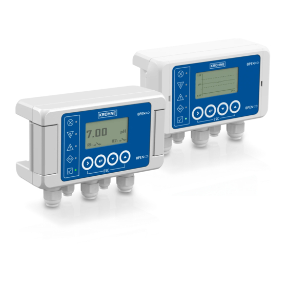
- Page 1 SMARTMAC 400 Handbook Control and calibration unit for digital SMARTPAT sensors The documentation is only complete when used in combination with the relevant documentation for the sensor. © KROHNE 07/2022 - 4008875401 - MA SMARTMAC_400 R01 en...
- Page 2 All rights reserved. It is prohibited to reproduce this documentation, or any part thereof, without the prior written authorisation of KROHNE Messtechnik GmbH. Subject to change without notice. Copyright 2022 by KROHNE Messtechnik GmbH - Ludwig-Krohne-Str. 5 - 47058 Duisburg (Germany) www.krohne.com 07/2022 - 4008875401 - MA SMARTMAC_400 R01 en...
-
Page 3: Table Of Contents
CONTENTS SMARTMAC 400 1 Safety instructions 1.1 Certifications ........................5 1.2 Software history ....................... 6 1.3 Intended use ........................6 1.4 Safety instructions from the manufacturer ..............7 1.4.1 Copyright and data protection ....................7 1.4.2 Disclaimer ..........................8 1.4.3 Product liability and warranty ....................9 1.4.4 Information concerning the documentation................ - Page 4 CONTENTS SMARTMAC 400 6.2 Menu mode ........................32 6.2.1 Menu mode structure ......................32 6.2.2 Status messages and diagnostic information ..............34 6.3 Function tables ....................... 37 6.4 Setup..........................59 6.4.1 Configuration of measurement page..................59 6.4.2 Number format ........................64 6.4.3 Configuration of loop 1......................
-
Page 5: Safety Instructions
CE marking. For full information of the EU directives and standards and the approved certifications, please refer to the EU declaration on the KROHNE website. Hazardous areas • ATEX II 2 G Ex ia IIC T4 Gb... -
Page 6: Software History
Changes and Documentation revision compatibility 03/2022 ER 2.0.X_ MA SMARTMAC 400 R01 1.3 Intended use DANGER! For devices used in hazardous areas, additional safety notes apply; please refer to the Ex documentation. CAUTION! Responsibility for the use of the measuring devices with regard to suitability, intended use and corrosion resistance of the used materials against the measured fluid lies solely with the operator. -
Page 7: Safety Instructions From The Manufacturer
The manufacturer is not liable for any damage resulting from improper use or use for other than the intended purpose. The SMARTMAC 400 is a loop powered control and calibration unit for digital SMARTPAT sensors. For process control, different features like relays, an additional second current output and LEDs for status signalisation according to NAMUR NE 107 are available. -
Page 8: Disclaimer
SAFETY INSTRUCTIONS SMARTMAC 400 1.4.2 Disclaimer The manufacturer will not be liable for any damage of any kind by using its product, including, but not limited to direct, indirect or incidental and consequential damages. This disclaimer does not apply in case the manufacturer has acted on purpose or with gross negligence. -
Page 9: Product Liability And Warranty
SAFETY INSTRUCTIONS SMARTMAC 400 1.4.3 Product liability and warranty The operator shall bear responsibility for the suitability of the device for the specific purpose. The manufacturer accepts no liability for the consequences of misuse by the operator. Improper installation or operation of the devices (systems) will cause the warranty to be void. -
Page 10: Warnings And Symbols Used
SAFETY INSTRUCTIONS SMARTMAC 400 1.4.5 Warnings and symbols used Safety warnings are indicated by the following symbols. DANGER! This warning refers to the immediate danger when working with electricity. DANGER! This warning refers to the immediate danger of burns caused by heat or hot surfaces. -
Page 11: Device Description
DEVICE DESCRIPTION SMARTMAC 400 2.1 Scope of delivery INFORMATION! Inspect the packaging carefully for damages or signs of rough handling. Report damage to the carrier and to the local office of the manufacturer. INFORMATION! Do a check of the packing list to make sure that you have all the elements given in the order. -
Page 12: Device Description
DEVICE DESCRIPTION SMARTMAC 400 2.2 Device description Figure 2-2: Device description 1 Display 2 Operation keys 3 Cable glands 4 High-brightness LEDs for NAMUR NE 107 status signalisation This 2-wire device can be connected to digital SMARTPAT sensors. Without additional accessories, the calibration and configuration of the sensors can be performed directly at the application. -
Page 13: Nameplate
DEVICE DESCRIPTION SMARTMAC 400 2.3 Nameplate INFORMATION! Look at the device nameplate to ensure that the device is delivered according to your order. Check for the correct supply voltage printed on the nameplate. SMARTMAC 400 LOOP 1: Ui=30V Ii=120mA Pi=1W Ci=45nF Li=0... -
Page 14: Installation
INSTALLATION SMARTMAC 400 3.1 General notes on installation INFORMATION! Inspect the packaging carefully for damages or signs of rough handling. Report damage to the carrier and to the local office of the manufacturer. INFORMATION! Do a check of the packing list to make sure that you have all the elements given in the order. -
Page 15: Point-To-Point Connection - Analogue / Digital Mode
SMARTMAC 400 3.3 Point-to-Point connection - analogue / digital mode With the SMARTMAC 400, you have direct access to all sensor functions. In case a sensor connection via PC or HART field communicator is nevertheless desired, please note the correct master settings. -
Page 16: Pre-Installation Requirements
If you ® • parameterise or calibrate your SMARTPAT sensor using PACTware with a HART modem, the master mode of the SMARTMAC 400 should be "Secondary" ® • parameterise or calibrate your SMARTPAT sensor with a HART field communicator, the master mode of the SMARTMAC 400 should be "Primary"... -
Page 17: Opening The Housing
INSTALLATION SMARTMAC 400 3.5 Opening the housing INFORMATION! Clean and grease all threads each time you open the housing. Use only resin-free and acid-free grease. Before closing the cover, ensure that the housing gasket is properly fitted, clean and undamaged. - Page 18 INSTALLATION SMARTMAC 400 Opening the aluminium housing Figure 3-3: Opening the aluminium housing • Pull only the right hinge lock the side 1. • Loosen the 2 torx screws (TX20) with a torx screwdriver 2. • Lift up the housing 3.
-
Page 19: Wall Mounting
INSTALLATION SMARTMAC 400 3.6 Wall mounting CAUTION! Always note the following items to ensure a proper and safe installation: • Make sure that there is adequate space to the sides. • The device must not be heated by radiated heat (e.g. exposure to the sun) to a electronics housing surface temperature above the maximum permissible ambient temperature. -
Page 20: Aluminium Housing
INSTALLATION SMARTMAC 400 3.6.2 Aluminium housing Figure 3-5: Wall mounting of the aluminium housing 1 Mark the holes with a suitable pen 1. 2 Drill the 4 holes and fasten the device securely to the wall 2. INFORMATION! For outdoor mounting, we recommend the optional weather protection cover XGSH010000 for wall and pipe mounting. -
Page 21: Electrical Connections
Check for the correct supply voltage printed on the nameplate. 4.2 Important device-specific notes on electrical connection INFORMATION! The SMARTMAC 400 is a loop powered device and has no function if no SMARTPAT sensor is connected. INFORMATION! Use only shielded cables for connection with the control system (e.g. PLC). -
Page 22: Connection Diagram Overview
ELECTRICAL CONNECTIONS SMARTMAC 400 4.3 Connection diagram overview Sens+ Sens- K FE A1 B1 A2 B2 Figure 4-1: Connection diagram overview 1 Terminals for loop 2 2 Terminal for functional earth 3 Terminals for sensor connection 4 Terminals for external HART-Modem / external HART-adapter 5 Terminals for loop 1: Connect D and E when the power supply has an internal resistor or C and E to use the internal resistor of this device. - Page 23 ELECTRICAL CONNECTIONS SMARTMAC 400 K FE A1 B1 A2 B2 Figure 4-2: Connection example with a 2-wire field device 1 Power supply for loop 2. Used for second 4...20 mA output and/or NE107 LEDs and backlight. 2 Connected field device, e.g. SMARTPAT PH.
-
Page 24: Connecting The Field Device Cable
ELECTRICAL CONNECTIONS SMARTMAC 400 4.4 Connecting the field device cable CAUTION! When connecting the power supply, always note the safety regulations of the current state of the art. To avoid fatal injuries, destruction or damage of the device or measuring errors, also note the following items: •... -
Page 25: Connecting The Second Current Output
ELECTRICAL CONNECTIONS SMARTMAC 400 4.5 Connecting the second current output Sens+ Sens- K FE A1 B1 A2 B2 A1 B1 A2 B2 Figure 4-4: Connection of second current output The second current output can be either used as current output for any measurand of a SMARTPAT sensor or as power supply for backlight and LEDs for NAMUR NE 107 signalisation. -
Page 26: Connecting The Relay Outputs
ELECTRICAL CONNECTIONS SMARTMAC 400 4.6 Connecting the relay outputs The device has two solid state relays that can work as status output, system alarm, cleaning control or limit switch: • The relay contacts are electrically isolated from each other and from all other circuits. -
Page 27: Connecting The External Hart Adapter
SMARTMAC 400 4.7 Connecting the external HART adapter With the SMARTMAC 400, you have direct access to all sensor functions. In case a sensor connection via PC or HART field communicator is nevertheless desired, the internal or optional external HART adapter can be used. By using the external HART adapter, it is not necessary to open the housing. -
Page 28: Power Supply
ELECTRICAL CONNECTIONS SMARTMAC 400 4.8 Power supply DANGER! To avoid fatal injuries as well as destruction or damage of the device assure a correct installation before switching on the power. This includes: • The device is mechanically safe, mounting and power connection comply with the regulations. -
Page 29: Start-Up
START-UP SMARTMAC 400 5.1 Start-up DANGER! To avoid fatal injuries as well as destruction or damage of the device assure a correct installation before switching on the power. This includes: • The device is mechanically safe, mounting and power connection comply with the regulations. - Page 30 START-UP SMARTMAC 400 When the search was successful, the display shows the KROHNE product name of the SMARTPAT sensor. HART devi ce f ound . . . KROHNE SM ARTPAT PH Figure 5-2: Product name of the SMARTPAT sensor www.krohne.com...
-
Page 31: Operation
OPERATION SMARTMAC 400 6.1 Operating elements The operation elements consist of the four operation keys: Operating key Symbol in text The function of a key depends on the mode of the device and on the menu level: Measuring mode Menu mode... -
Page 32: Menu Mode
OPERATION SMARTMAC 400 6.2 Menu mode The menu mode consists of four main menus with a couple of different sub-levels. Altogether there are the following levels: • Main menu levels • First and second submenu levels • Parameter level 6.2.1 Menu mode structure... - Page 33 OPERATION SMARTMAC 400 Mainmenu Submenu B PAT sensor B1 Calibration COND B1.1 Start calibration B1.2 Cell constant B2 Calibration PH B2.1 Two point calibration B2.2 One point calibration B3 Calibration ORP B3.2.2 All outputs on hold? B3.3.1 Set redox solution B3.4.1 ORP solution ready?
-
Page 34: Status Messages And Diagnostic Information
OPERATION SMARTMAC 400 6.2.2 Status messages and diagnostic information The diagnostic messages are displayed in accordance with NAMUR standard NE 107. INFORMATION! As status message always the name of the relevant status group and the status symbol is displayed. Each status message (= status signal) has a specific symbol, determined by NAMUR, which is displayed with the message. - Page 35 OPERATION SMARTMAC 400 Error category Error group Error message Description Action according to NAMUR NE 107 Failure Sensor Device The field device sensor Check field device sensor malfunction reports device malfunction and replace it if necessary. (2nd status byte) Access restriced...
- Page 36 (2nd 20 mA values. status byte) Out of Process L2 under- The measurement value is Check SMARTMAC 400 Loop specification saturation out of range. The current is 2 configuration of 4 and limited by the lower limit of 20 mA.
-
Page 37: Function Tables
OPERATION SMARTMAC 400 Error category Error group Error message Description Action according to NAMUR NE 107 Maintenance Sensor Slope Slope < -65mV/Ph Calibrate field device. If required <- 65mV/pH slope is still<-65 mV, replace the field device. Slope Slope > -50mV/Ph Calibrate field device. - Page 38 OPERATION SMARTMAC 400 Menu level Designation / function Settings / descriptions A3.3 User specific address ® User specific address for HART devices (only displayed if "User specific address" is selected in A.3.2) A3.3.1 User specific address ® User specific address for HART devices (only displayed if "User specific...
- Page 39 OPERATION SMARTMAC 400 Menu level Designation / function Settings / descriptions A4.2.1 Main value Setting of main value Options: • • • • • 4…20 mA (L1) • 4…20 mA (L2) A4.2.2 Additional value Setting of additional value Options: •...
- Page 40 OPERATION SMARTMAC 400 Menu level Designation / function Settings / descriptions A4.3.5 Value line four Selection of fourth displayed measuring value Options: • • • • • 4…20 mA (L1) • 4…20 mA (L2) A4.4 Trend graph Configuration of Trend graph A4.4.1...
- Page 41 OPERATION SMARTMAC 400 Menu level Designation / function Settings / descriptions A4.5.2 Decimals PV Settings of decimals for PV Options: • Automatic • #N.XXXX • #N.XXX • #N.XX • #N.X A4.5.3 Digits SV Settings of digits for SV Range: 002…006 A4.5.4...
- Page 42 OPERATION SMARTMAC 400 Menu level Designation / function Settings / descriptions A4.5.12 Decimals 4…20 mA L2 Settings of decimals for 4…20 mA L2 Options: • Automatic • #N.XXXX • #N.XXX • #N.XX • #N.X A4.6 Illumination settings Illumination Settings (only displayed if Current output or Power supply is selected in A5.3.1).
- Page 43 OPERATION SMARTMAC 400 Menu level Designation / function Settings / descriptions A5.3.1 Mode Operating mode of 2. current output Options: • • Power Supply • Current Output A5.3.3 Variable selection Selection of displayed value (only displayed if Current Output is selected in A5.3.1)
- Page 44 OPERATION SMARTMAC 400 Menu level Designation / function Settings / descriptions A5.4.1 Mode Operating mode of the relays Options: • • Limit switch (band) • Limit switch (thres.) • Field device status • USP<645> • Loop 1 error current •...
- Page 45 OPERATION SMARTMAC 400 Menu level Designation / function Settings / descriptions A5.4.21 Field device status Selection of the NAMUR-status of the SMARTPAT sensor, at which the relay switches (only displayed if Field device status is selected in A5.4.1) Options: •...
- Page 46 OPERATION SMARTMAC 400 Menu level Designation / function Settings / descriptions A5.4.34 Stop cleaning Stop cleaning? (only displayed if Cleaning Mode is selected in A5.4.1 Options: • • A5.5 Relay 2 Settings for Relay 2 A5.5.1 Mode Operating mode of the relays Options: •...
- Page 47 OPERATION SMARTMAC 400 Menu level Designation / function Settings / descriptions A5.5.21 Field device status Selection of the NAMUR-Status of the SMARTPAT sensor, at which the relay switches (Only displayed if Field device status is selected in A5.5.1) Options: •...
- Page 48 OPERATION SMARTMAC 400 Menu level Designation / function Settings / descriptions Calibration Calibration of SMARTPAT COND sensor (only displayed if SMARTPAT COND sensor is connected) B1.1 Start calibration Start of SMARTPAT COND sensor calibration (only displayed if SMARTPAT COND sensor is connected) B1.1.2.1...
- Page 49 OPERATION SMARTMAC 400 Menu level Designation / function Settings / descriptions B1.1.5.2 Set unit of calib. sol. Set unit of calibration solution (only displayed if SMARTPAT COND sensor is connected and if Calibration solution is selected in B1.1.2.1) Options: •...
- Page 50 OPERATION SMARTMAC 400 Menu level Designation / function Settings / descriptions B2.1.3.1 Temperature comp. Setting temperature compensation (only displayed if SMARTPAT PH sensor is connected) Options: • Automatic • Manual B2.1.3.2 Set temp. comp. Setting the compensation temperature (only displayed if SMARTPAT PH sensor is connected and Manual is selected in B2.1.3.1)
- Page 51 OPERATION SMARTMAC 400 Menu level Designation / function Settings / descriptions B3.3.1 Set redox solution Setting the redox solution (only displayed if SMARTPAT ORP sensor is connected) -Min…Ma B3.4.1 ORP solution ready? Is ORP solution ready? (only displayed if SMARTPAT ORP sensor is connected) B3.4.3...
- Page 52 OPERATION SMARTMAC 400 Menu level Designation / function Settings / descriptions B5.1.2 Manual hold? Activate manual hold to avoid an alarm Options: • • B5.1.4.1 Hold second loop? Activate manual hold for second loop (only displayed if second loop is activated in A5.3.1)
- Page 53 OPERATION SMARTMAC 400 Menu level Designation / function Settings / descriptions B5.2.6.2 Set mode Settings for temperature compensation mode (only displayed if SMARTPAT COND sensor is connected) Options: • • Linear • Natural water • Ultrapure water (will be implemented soon) B5.2.7...
- Page 54 OPERATION SMARTMAC 400 Menu level Designation / function Settings / descriptions B5.4.1 Measurand Measurand settings (only displayed if SMARTPAT COND sensor is connected) B5.4.1.2 Set measurand Setting of the measurand (only displayed if SMARTPAT COND sensor is connected) Options: •...
- Page 55 OPERATION SMARTMAC 400 Menu level Designation / function Settings / descriptions B5.5.4.5 Temperature Temperature is displayed (only displayed if SMARTPAT PH sensor is connected) -Min…Max B5.5.4.6 Max. temperature Max. temperature is displayed (only displayed if SMARTPAT PH sensor is connected) B5.5.4.7...
- Page 56 OPERATION SMARTMAC 400 Menu level Designation / function Settings / descriptions B5.6.1.1 Order code Order code is displayed B5.6.1.2 Device name Device name is displayed B5.6.1.3 Serial number Serial number is displayed B5.6.1.4 HART ID HART ID is displayed B5.6.1.5...
- Page 57 OPERATION SMARTMAC 400 Menu level Designation / function Settings / descriptions B5.6.3.7 Max. temperature Max. operating temperature is displayed (only displayed if SMARTPAT PH sensor is connected) B5.6.3.8 Temperature comp. Temperature compensation selected in B5.2.3.2 is displayed (only displayed if SMARTPAT PH sensor is connected) B5.6.3.9...
- Page 58 OPERATION SMARTMAC 400 Menu level Designation / function Settings / descriptions B6.1.2.2 20mA trimming 20mA trimming Use and to trim. B6.2 Reset Reset execution B6.2.2 Reset? Do you want to execute a reset? Options: • • B6.3 Factory reset Factory reset execution B6.3.2...
-
Page 59: Setup
OPERATION SMARTMAC 400 Menu level Designation / function Settings / descriptions E1.3 Start simulation? Start simulation? Options: • • E1.4 Set QV Range: -Min…Max E1.4 Start simulation? Start simulation? Options: • • Loop 2 Test of Loop 2 (only displayed if Loop 2 is activated in A5.3.1) E2.1... - Page 60 OPERATION SMARTMAC 400 1. Measurement page 7. 47 Figure 6-1: 1. Measurement page 1 TAG 2 Measuring unit 3 Relay 2 status 4 Relay 1 status 5 Measuring value The 1. Measurement page shows one large value with the corresponding unit.
- Page 61 OPERATION SMARTMAC 400 For the displayed values you can chose between PV, SV, TV, QV, 4…20 mA (L1) in menu option A4.2. Those options are for both variables. 3. Measurement page Figure 6-3: 3. Measurement page 1 TAG 2 Relay 1 status 3 Relay 2 status 4 4.
- Page 62 OPERATION SMARTMAC 400 Trend graph 7. 00 5. 00 800 s Figure 6-4: Trend graph 1 TAG 2 Limit line (for example relay 1) 3 Trend graph 4 Limit line (for example relay 2) 5 Span 6 Measuring unit The trend graph shows a graph of the measured values (y-axis) for a predefined time period (x-axis).
- Page 63 OPERATION SMARTMAC 400 Graph summary 800 s Figure 6-5: Graph summary 1 TAG 2 Span 3 Max. measured value 4 Min. measured value 5 Average measured value On the Graph summary, the measured values for the configured parameters are evaluated for the defined span.
-
Page 64: Number Format
OPERATION SMARTMAC 400 6.4.2 Number format The function “Number format” in menu A4.5 allows to define the number format of each measuring value. You can configure the number of digits and the decimals of PV, SV, TV, QV, 4…20 mA L1 and 4…20 mA L2. -
Page 65: Function Of Relay 1 + 2
OPERATION SMARTMAC 400 6.4.5 Function of relay 1 + 2 To configure relay 1 and 2, go to menu A5.4 respectively A5.5. Limit switch (band) In Limit switch (band) mode, you define a permitted measuring range (band). When the measuring value exceeds or falls below this range, the relay switches. - Page 66 OPERATION SMARTMAC 400 Limit switch (threshold) In Limit Switch (Threshold) mode, you define a threshold. When the measuring value exceeds or falls below this threshold, the relay switches. Decide wether the relay opens (inverted) or closes (not inverted) when the value exceeds or falls below the threshold.
-
Page 67: Configuration Of Relay 1+2
OPERATION SMARTMAC 400 Figure 6-9: Limit switch (threshold) overrun direction 1 Threshold 2 Hysteresis 3 Relay closed (not inverted) 4 Relay open (not inverted) 5 Relay closed (inverted) 6 Relay open (inverted) 6.4.6 Configuration of relay 1+2 You can choose between Limit switch (threshold), Limit switch (band), Off, cleaning mode, System alarm, Loop 1 error current, USP<645>... - Page 68 OPERATION SMARTMAC 400 Press > to enter the main menu. Press or until the submenu Setup is highlighted and press > to enter the submenu. Press or until the submenu I/O is highlighted and press > to enter the submenu.
- Page 69 OPERATION SMARTMAC 400 System alarm Use of the relays for system alarm Press > to enter the main menu. Press or until the submenu Setup is highlighted and press > to enter the submenu. Press or until the submenu I/O is highlighted and press > to enter the submenu.
- Page 70 OPERATION SMARTMAC 400 Field device status Use of the relays for a SMARTPAT sensor status Press > to enter the main menu. Press or until the submenu Setup is highlighted and press > to enter the submenu. Press or until the submenu I/O is highlighted and press > to enter the submenu.
-
Page 71: Illumination Setting
OPERATION SMARTMAC 400 Cleaning mode Use of relay 1 for sensor cleaning control Press > to enter the main menu. Press or until the submenu Setup is highlighted and press > to enter the submenu. Press or until the submenu I/O is highlighted and press > to enter the submenu. -
Page 72: Overflow Sign And Exponential Format
OPERATION SMARTMAC 400 6.4.8 Overflow sign and exponential format If there is not enough space available for the complete measured value, the display either shows the overflow sign or uses the exponential format (depending on the settings in functions). Overflow sign The user can define that a particular display line should consist of a fixed number of digits in menu A4.5. -
Page 73: Smartpat Sensor Calibration
OPERATION SMARTMAC 400 6.5 SMARTPAT sensor calibration INFORMATION! For sensor handling during calibration please consider the standard documentation of the sensor! To start a sensor calibration proceed as follows: Press > to enter the main menu. Press or until the submenu PAT sensor is highlighted and press > to enter the submenu. -
Page 74: Smartpat Orp Sensor Calibration
OPERATION SMARTMAC 400 Calibration solution Press > to enter the submenu Start calibration. Choose calibration method Calibration solution and press ^. Choose between Yes and No to set all outputs on hold or not and press ^. Choose unit of calibration solution between µS/cm and mS/cm for measurand (B5.4.1.2) conductivity orMOhm*cm and kOhm*cm for measurand (B5.4.1.2) resistivity and press ^. -
Page 75: Smartpat Ph Sensor Calibration
OPERATION SMARTMAC 400 6.5.3 SMARTPAT PH sensor calibration Two calibration methods are possible: "One point calibration" with a reference sensor (will be implemented in SMARTPAT PH sensors soon) "Two point calibration" with two buffer solutions Two point calibration Choose Two point calibration and press ^. -
Page 76: Sensor Exchange Function
OPERATION SMARTMAC 400 6.6 Sensor exchange function With the sensor exchange function, settings from a SMARTPAT sensor can be copied to another when replacing an old sensor with a new one. Load settings from old sensor Press > to enter the main menu Press ... -
Page 77: Service
SERVICE SMARTMAC 400 7.1 Maintenance and repair The device is maintenance free. Also note the following admonition concerning malfunctions: DANGER! In case of a malfunction only the technical service is allowed to repair the device. Never try to repair the device on your own, otherwise it may come to fatal injuries, destruction or damage of the device or measuring errors. -
Page 78: Form (For Copying) To Accompany A Returned Device
SERVICE SMARTMAC 400 7.4.2 Form (for copying) to accompany a returned device CAUTION! To avoid any risk for our service personnel, this form has to be accessible from outside of the packaging with the returned device. Company: Address: Department: Name:... -
Page 79: Disassembly And Recycling
SERVICE SMARTMAC 400 7.5.1 Disassembly and recycling This section briefly describes the instructions of handling and disassembling the device when it has reached the end of its useful life (EOL) or is disposed of after usage. The information given is sufficient to gather the most important parts of the device (by the end-user) which can be used for recycling. - Page 80 SERVICE SMARTMAC 400 Figure 7-2: Overview disassembly- plastic housing Component Plastic version Aluminium version Material Weight [g/lb] Material Weight [g/lb] Housing 197 / 0.43 Aluminium 645 / 1.42 Cable glands PA6 V-2, CR / 31 / 0.07 PA6 V-2, CR / 31 / 0.07...
- Page 81 SERVICE SMARTMAC 400 INFORMATION! The percentage of hazardous substances present in the components complies with RoHS. INFORMATION! The product does not contain harmful gases or substances. There are no special guidance or actions necessary to disassemble the device. CAUTION! Before disassembling the device, make sure you have the proper tools needed.
-
Page 82: Technical Data
TECHNICAL DATA SMARTMAC 400 8.1 Technical data INFORMATION! • The following data is provided for general applications. If you require data that is more relevant to your specific application, please contact us or your local sales office. • Additional information (certificates, special tools, software,...) and complete product documentation can be downloaded free of charge from the website (Downloadcenter). - Page 83 TECHNICAL DATA SMARTMAC 400 Installation conditions Weight Approx. 413 g / 0.91 lb for plastic housing Approx. 855 g / 1.89 lb for aluminium housing Installation Wall mounting; assure a vertical mounting orientation Wall or pipe mounting with weather protection cover...
-
Page 84: Dimensions
TECHNICAL DATA SMARTMAC 400 8.2 Dimensions Plastic housing Figure 8-1: Dimensions plastic housing Dimensions [mm] Weight [g] Wall mounted Table 8-1: Dimensions plastic housing in mm Dimensions [inch] Weight [pound] Wall mounted 3.15 5.94 2.36 4.13 0.91 Table 8-2: Dimensions plastic housing in inch www.krohne.com... - Page 85 TECHNICAL DATA SMARTMAC 400 Aluminium housing Figure 8-2: Dimensions aluminium housing Dimensions [mm] Weight [g] Wall mounted Table 8-3: Dimensions aluminium housing in mm Dimensions [inch] Weight [pound] Wall mounted 3.39 6.26 2.36 4.37 1.89 Table 8-4: Dimensions aluminium housing in inch 07/2022 - 4008875401 - MA SMARTMAC_400 R01 en www.krohne.com...
- Page 86 NOTES SMARTMAC 400 www.krohne.com 07/2022 - 4008875401 - MA SMARTMAC_400 R01 en...
- Page 87 NOTES SMARTMAC 400 07/2022 - 4008875401 - MA SMARTMAC_400 R01 en www.krohne.com...
- Page 88 Engineering, commissioning, calibration, maintenance and training services Head Office KROHNE Messtechnik GmbH Ludwig-Krohne-Str. 5 47058 Duisburg (Germany) Tel.: +49 203 301 0 Fax: +49 203 301 10389 info@krohne.de The current list of all KROHNE contacts and addresses can be found at: www.krohne.com...
Need help?
Do you have a question about the SMARTMAC 400 and is the answer not in the manual?
Questions and answers