Dynon Avionics SkyView HDX Airplane Flight Manual Supplement
Hide thumbs
Also See for SkyView HDX:
- Pilot's user manual (260 pages) ,
- Installation & maintenance manual (69 pages) ,
- Installation manual (49 pages)

Related Manuals for Dynon Avionics SkyView HDX


Summary of Contents for Dynon Avionics SkyView HDX
- Page 1 SkyView Airplane Flight Manual Supplement (or Supplemental Airplane Flight Manual) 103272-000 SkyView Airplane Flight Manual Supplement, Rev N, 10/23/2020 Page | i...
- Page 2 Contact Information Dynon Avionics, Inc. 19825 141st Place NE Woodinville, WA 98072 Phone: 425-402-0433 Business Operations: 8:00 AM–5:00 PM (Pacific Time) Monday–Friday Technical Support Operations: 7:30 AM–4:00 PM (Pacific Time) Monday–Friday Email Sales: sales@dynoncertified.com Email Support: support@dynoncertified.com Web: www.dynoncertified.com Copyright ©2020 Dynon Avionics, Inc.
- Page 3 This document serves as a supplement to the aircraft flight manual, or as a supplemental flight manual. It must be attached to the FAA Approved Airplane Flight Manual (AFM) or, when no AFM exists, used as a supplemental aircraft operating manual when the Dynon Avionics SkyView HDX System is installed in accordance with STC SA02594SE.
- Page 4 "FAR 23.1545" • Changed wording in section 5.5 to read "pull" instead of "turn off" with reference to circuit breakers. • Updated Figure 18 • Changed name of document from "SkyView HDX Airplane Flight 7/2/2019 ECO 331341 Manual Supplement" • Added note regarding use of this document as an SAFM.
- Page 5 DATE APPROVED DESCRIPTION OF CHANGE • Addressed FAA review comments on Rev H, including: ▪ Update Section 2: System Overview to better distinguish between Primary, Secondary, and Standby EFIS displays. ▪ Replace Section 3: Flight Crew Alerting System with new, updated information.
- Page 6 DATE APPROVED DESCRIPTION OF CHANGE • Addressed FAA review feedback on Rev H: ▪ Re-ordered Table 1: Warnings, Table 2 Cautions, and Table 3: Messages. Ordering is by 1) core system, 2) component, 3) function per type of alert. ▪ Updated Section 4.2.1, 4.2.3, and 4.2.3 with additional screenshots and verbiage to clearly differentiate single- and twin-engine EMS indications.
- Page 7 DATE APPROVED DESCRIPTION OF CHANGE • Moved FAA Approval page to first page per GAMA 1 guidelines. • Moved References page to Section 1: General • Added new Section 2.2: Engine Monitoring Visibility to Section 2: Limitations. Subsequent Section 2 headings renumbered. •...
-
Page 8: Table Of Contents
Emergency Procedures ..................... 3-1 Non-Normal Procedures .................... 3-3 Normal Operations .................. 4-1 General ........................4-1 SkyView HDX Backup Power Check ................. 4-8 EFIS-D10A Standby Display Backup Battery Condition Check ......... 4-8 Autopilot Controls ...................... 4-8 Autopilot Operation Check ..................4-13 Performance ..................... - Page 9 Supplements .................... 9-1 Autopilot ........................9-1 Appendix 1: Cessna Models 172F through 172S ....... 10-1 10.1 Autopilot Limitations ....................10-1 10.2 Autopilot Servo Frangible Link Break-Away Forces ..........10-1 Appendix 2: Beechcraft Bonanza P35 through V35B ......11-1 11.1 Autopilot Limitations ....................11-1 11.2 Autopilot Servo Frangible Link Break-Away Forces ..........
- Page 10 This page intentionally left blank. SkyView Page | x 10/23/2020 Airplane Flight Manual Supplement, Rev N,...
-
Page 11: General
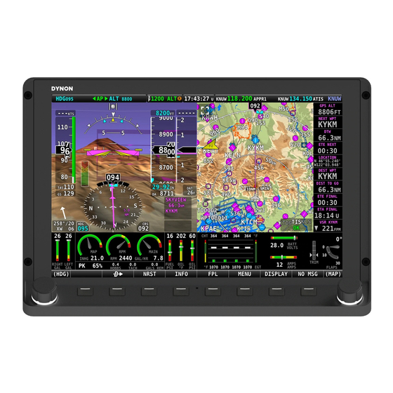
SkyView HDX is an integrated system that aggregates air, engine, traffic, and navigation information for display to the pilot. The information is portrayed on the SkyView HDX display, which is a touchscreen, coupled with mechanical knobs and buttons. The SkyView HDX display provides Primary Flight Information (PFI) on the Primary Flight Display (PFD), Map with current position, and optionally Engine Monitoring information. - Page 12 This page intentionally left blank. SkyView Page | 1-2 10/23/2020 Airplane Flight Manual Supplement, Rev N,...
-
Page 13: Limitations
IFR Operations For IFR operations, the SkyView HDX system must have at least one of each of the following components in fully functioning condition, with no System Setup error messages: For all airplanes: •... -
Page 14: Synthetic Vision
Synthetic Vision For all airplanes: • SkyView HDX Synthetic Vision is advisory in nature and must not be used as the sole means of terrain and obstacle avoidance. For all airplanes: • The SkyView HDX Map and Flight Planning function is advisory in nature and must not be used as the sole means of terrain and obstacle avoidance. -
Page 15: Emergency & Non-Normal Procedures
Emergency & Non-Normal Procedures Emergency Procedures Airspeed, Altitude, and/or Attitude Unreliable CONDITION: The pitch attitude is not consistent with airspeed, vertical speed, or altimeter indications, and one of the following is true: • Airspeed reads "0" on all flight indicators, and CHECK PITOT HEAT Caution Alert is active, requiring immediate pilot action. - Page 16 Autopilot / Yaw Damper Disable CONDITION: One or more Autopilot servos are operating in a confusing or un-commanded fashion. 1. AP Power Switch ____________________________________________________ OFF. 2. Fly Manually. • Power has been removed from the Autopilot servos. Autopilot / Yaw Damper Servo Jam CONDITION: One or more flight controls fail to move as expected and are jammed by an Autopilot servo.
-
Page 17: Non-Normal Procedures
Non-Normal Procedures Loss of Airspeed, Altitude, Attitude, and/or Heading Display CONDITION: Red X replaces the airspeed, altitude, attitude and/or heading indicators. If the Autopilot is engaged, the AUTOPILOT DISCONNECT Warning Alert annunciates. 1. AP DISC Button___________________________________________________ PRESS. 2. Aircraft Attitude _____________________ MAINTAIN / REGAIN AIRCRAFT CONTROL. 3. - Page 18 GPS Position Source Failure CONDITION: POSITION SOURCE FAIL is shown on the display. 1. Use other navigational means. • The system has no remaining GPS positions sources available. • The Map is no longer available. Autopilot Disconnect CONDITION: The Autopilot needs to be disconnected for any reason other than normal operations.
-
Page 19: Normal Operations
Normal Operations General Although operation of the primary functions of the SkyView HDX system is intuitive, it does require a reasonable degree of familiarity to utilize all its functions without compromising attention to other flying tasks. Users are encouraged to read the SkyView Pilot's User Guide... - Page 20 Touch Controls SkyView HDX displays contain touchscreen functionality. Touching various items on the display allows for the item to be selected and the value adjusted. For example, touching the HSI data source allows for alternate sources to be selected. Pilot-selectable choices for the layout of each screen can be selected by pressing DISPLAY button on Main Menu.
- Page 21 HSI Data Source To cycle through the available sources of navigation data for display on HSI: • Press MENU button on Main Menu, then select PFD TOOLS > HSI SRC. Repeated touches of HSI SRC will cycle through available HSI data sources. •...
- Page 22 ▪ Standard pressure is set (29.92 inHg or 1013 millibars when at/above 18k feet or no ADS-B on board). ▪ Altimeter is set to match the published airport elevation (when on the ground). ▪ Altimeter is set to match GPS altitude (when on the ground). If none of the conditions in Table 1 are met, the Altimeter will not synchronize and a NO...
- Page 23 Altitude Bug The Altimeter can be adjusted with the left knob on the display or the ALT knob on the optional Knob Control Panel (see Section 4.1.11). Using the knob on the control panel simplifies the adjustment by eliminating the need to assign the function to the left knob. To change the Altitude bug: 1.
- Page 24 Course (OBS) Setting To set the HSI course (OBS): Press left knob to enter Knob Function Menu. Rotate knob to highlight CRS. Push knob to close menu (menu will also close automatically after 5 seconds). This assigns CRS to knob, and CRS is shown above knob. The HIS course area on the PFD is also outlined to show that it is selected.
- Page 25 VHF COM Radio The optional COM Radio Control Panel (see Figure 4) tunes frequencies by airport and station type and allows the simultaneous reception of two frequencies, referred to as Dual Mode. To use the radio: Press the APT button and use the knob to scroll through nearby airports. Press the knob to select an airport.
-
Page 26: Skyview Hdx Backup Power Check
SkyView HDX Backup Power Check When the SkyView HDX system detects that it is not moving, and power is removed from a display connected to a backup battery, the system will automatically run an additional 30 seconds on backup battery power. This is so it can complete a battery condition test. The result of the test will appear in the battery status indicator at next system startup. - Page 27 Green indicates a radio-based source (VOR or localizer). The optional Autopilot Control Panel (see Figure 5) for the SkyView HDX Autopilot provides dedicated buttons for engaging the Flight Director, Autopilot, and all control modes, including coupled approaches, VNAV, IAS Hold, and mode sequencing (provided that IFR navigation sources are installed).
- Page 28 Engage Flight Director The Flight Director is engaged by pressing the "FD" button instead of the "AP" button. To subsequently engage the servos, press the "AP" button. Disengage Autopilot The Autopilot can be disengaged with the AUTOPILOT DISCONNECT (AP DISC) button. An AP DISC button is included on the optional panel-mounted AP Control Panel, or the wheel/yoke- mounted button can be used.
- Page 29 Climb or Descend to a New Altitude at a Set Airspeed 1. Adjust the altitude bug to the new desired altitude. 2. Press the IAS button. The IAS bug will synchronize to the current airspeed. 3. NOSE UP / DN buttons to adjust the Autopilot’s target airspeed. Airspeed command is limited to the Autopilot minimum and maximum limits configured by the installer during initial system setup.
- Page 30 If an ILS approach is being flown with another navigation source being used in the transition, for example an approach approved GPS navigator, upon being cleared for and activating the approach the SkyView HDX's HSI source must be switched from GPS to NAV. This may happen one of two ways: 1.
-
Page 31: Autopilot Operation Check
Thus, when configured for auto-switching, you must use that navigators’ CDI or NAV/GPS toggle to change whether NAV or GPS guidance is shown on SkyView HDX’s HSI. SkyView HDX’s own HSI SRC button can only see EITHER the GPS or NAV side of the navigator at any time. - Page 32 The resistance offered by the servo indicates that the system is operating normally. Autopilot Disconnect Check With master switch and autopilot servo power switches ON: 1. Engage Autopilot. 2. Accomplish all that apply: • Press the AP button in the Autopilot Control menu, and ensure the autopilot disconnects.
-
Page 33: Performance
Performance No change to airplane performance. Refer to the airplane's Pilot's Operating Handbook and associated Aircraft Flight Manual and supplements. SkyView Airplane Flight Manual Supplement, Rev N, 10/23/2020 Page | 5-1... - Page 34 This page intentionally left blank. SkyView Page | 5-2 10/23/2020 Airplane Flight Manual Supplement, Rev N,...
-
Page 35: Weight And Balance
No change to airplane. Refer to the airplane's Pilot's Operating Handbook and associated Aircraft Flight Manual and supplements. Installation of a SkyView HDX system impacts the airplane's level weight and balance once, during initial installation. Certified installers must add new empty weight and balance information to airplane's Aircraft Flight Manual. - Page 36 This page intentionally left blank. SkyView Page | 6-2 10/23/2020 Airplane Flight Manual Supplement, Rev N,...
-
Page 37: System Overview
System Overview SkyView HDX Display Units Up to three SkyView HDX display units can be installed in the airplane’s instrument panel if space permits. The SkyView HDX display unit installed in the pilot's position is designated the Primary Display. It is configured during initial setup to always present PFD. It can also present Map and Engine Monitoring. -
Page 38: Navigation Databases
SkyView HDX Network as appropriate. Flight Crew Alerting System The Flight Crew Alerting System is a central feature of the SkyView HDX system. This system provides the pilot and crew with system information organized by priority for all installed SkyView HDX sub-systems. - Page 39 Messages • Messages are used for conditions that require immediate flight crew awareness and may require subsequent flight crew response. These alerts appear in the Message Notification Window described in Section 7.8.1. Notification Methods Whenever a new non-flightpath alert is triggered, the Alert Notification Indicator (i.e., button label) shown in Figure 6, flashes Red for Warning alerts, Yellow for Caution alerts, and Gray for...
- Page 40 Warning Alerts Warning Alerts are for conditions that require immediate flight crew awareness and immediate flight crew response. If the Warning alert is flightpath related, the alert appears on the PFD and not in the Alert Notification Window. Warning Alerts are Red and may have specific voice aural annunciations.
- Page 41 System sensor tests Do not fly. Monitor Standby INTERNAL ERROR performed on Display System. ADAHRS failed. ADAHRS FAIL "WARNING" SkyView HDX has Do not fly. SkyView PDF has detected a problem failed. with the ADAHRS Monitor Standby module. Display System.
- Page 42 WARNING ALERTS VISUAL AURAL PRE-FLIGHT IN-FLIGHT CONDITION INDICATION INDICATION ACTION ACTION AMPS HIGH "ELECTRICAL Electrical current Refer to Airplane Refer to Airplane CURRENT" indicator has entered Flight Manual Flight Manual configured Red High range. AMPS LOW "ELECTRICAL Electrical current Refer to Airplane Refer to Airplane CURRENT"...
- Page 43 WARNING ALERTS VISUAL AURAL PRE-FLIGHT IN-FLIGHT CONDITION INDICATION INDICATION ACTION ACTION FUEL PRES LOW "FUEL PRESSURE" Fuel Pressure Refer to Airplane Refer to Airplane indicator has entered Flight Manual Flight Manual configured Red Low range. LEVEL HIGH "FUEL QUANTITY" Fuel Quantity Refer to Airplane Refer to Airplane indicator has entered...
- Page 44 WARNING ALERTS VISUAL AURAL PRE-FLIGHT IN-FLIGHT CONDITION INDICATION INDICATION ACTION ACTION Autopilot Bar shows "AUTOPILOT The Autopilot is No action. Take command to ASPD HIGH AIRSPEED HIGH" applying nose up manually decrease inputs to protect the airplane's speed. airplane from exceeding the configured maximum Autopilot airspeed.
- Page 45 WARNING ALERTS VISUAL AURAL PRE-FLIGHT IN-FLIGHT CONDITION INDICATION INDICATION ACTION ACTION TRIM NOSE UP "TRIM NOSE UP" The Autopilot No action. Apply Nose Up Trim requires nose up until the message trim. Visual stops. annunciation appears immediately. Aural warning after 10 seconds.
- Page 46 Caution Alerts Caution Alerts are for conditions that require immediate flight crew awareness and subsequent flight crew response. Caution Alerts are Yellow and may have specific voice aural annunciations. Caution Alerts are dependent upon installed systems and components. See Table 3 for a full listing of Caution Alerts, ordered by 1) Core System, 2) Component, and 3) Function.
- Page 47 CAUTION ALERTS VISUAL AURAL PRE-FLIGHT IN-FLIGHT CONDITION INDICATION INDICATION ACTION ACTION CPU TEMP "CAUTION" The SkyView display Use remaining Monitor remaining CRITICAL unit presenting the SkyView display SkyView display message has units, if available. units and/or Standby critically high internal Display System.
- Page 48 CAUTION ALERTS VISUAL AURAL PRE-FLIGHT IN-FLIGHT CONDITION INDICATION INDICATION ACTION ACTION ACTV ADAHRS "CAUTION" The ADAHRS has Do not fly. Cross check and VIBRATION detected vibration monitor instruments. that affects If Autopilot is performance of enagaged, G-Meter, Attitude disengage, and turn indicator, and AP Power switch Autopilot.
- Page 49 CAUTION ALERTS VISUAL AURAL PRE-FLIGHT IN-FLIGHT CONDITION INDICATION INDICATION ACTION ACTION COM RADIO PNL "CAUTION" COM Radio control If Dynon COM radio Use alternate OFFLINE panel is not required for flight, do communication communicating with not fly. equipment. If none SkyView.
- Page 50 CAUTION ALERTS VISUAL AURAL PRE-FLIGHT IN-FLIGHT CONDITION INDICATION INDICATION ACTION ACTION POSITION SOURCE "CAUTION" The identified Verify that all Verify that all Navigation Navigation 'X' FAIL position source has Equipment is Equipment is failed. powered ON. powered ON. If message persists, If message persists, navigate using other navigate using other...
- Page 51 CAUTION ALERTS VISUAL AURAL PRE-FLIGHT IN-FLIGHT CONDITION INDICATION INDICATION ACTION ACTION AP TRIM "CAUTION" SkyView sent a Turn electric trim Turn electric trim MALFUNCTION command to move power OFF. Trim power OFF. Trim the trim motor, but aircraft manually. aircraft manually. did not receive Electric trim is Electric trim is...
- Page 52 SOFTWARE "MESSAGE" Software versions in Before flight, update Do not use SkyView MISMATCH SkyView HDX software to most HDX display unit display units do not current version in all presenting Red Xs match. displays in SETUP over indicators.
- Page 53 MESSAGES VISUAL AURAL PRE-FLIGHT IN-FLIGHT CONDITION INDICATION INDICATION ACTION ACTION (None) "APPROACHING The airplane is No action. Pilot awarness only. ALTITUDE" approaching the configured altitude. (None) "APPROACHING The airplane's No action. Pilot awarness only. MINIMUMS" altitude is 200 feet above the selected MINIMUM altitude.
- Page 54 MESSAGES VISUAL AURAL PRE-FLIGHT IN-FLIGHT CONDITION INDICATION INDICATION ACTION ACTION (None) "CHECK GEAR" Gear is not DOWN, Not Applicable. Confirm correct and airspeed is landing gear below configured position. Landing Gear Check Speed. SWITCH FUEL "SWITCH FUEL A reminder to switch Not Applicable.
- Page 55 MESSAGES VISUAL AURAL PRE-FLIGHT IN-FLIGHT CONDITION INDICATION INDICATION ACTION ACTION ROLL SERVO "MESSAGE" The Autopilot roll If AP Power Switch If AP Power Switch is OFF, Turn AP is OFF, Turn AP OFFLINE servo is not Power Switch ON. Power Switch ON. communicating or is not powered on.
-
Page 56: Indications
Indications Airspeed Indicators Installation of SkyView HDX does not necessitate changes to airplane's airspeed limitations. Refer to the Aircraft Limitations in the airplane's Aircraft Flight Manual (AFM) for the airspeed limitations. Configuration values for airspeed markings are entered into SkyView HDX during initial system setup. - Page 57 Figure 8: Airspeed Marking Examples SkyView Airplane Flight Manual Supplement, Rev N, 10/23/2020 Page | 7-21...
- Page 58 The optional SkyView HDX Engine Monitoring System (EMS) provides engine and airplane system information to the pilot. EMS information can be presented on a SkyView HDX display in three different size formats, depending upon owner/pilot preference or requirements of the airplane: •...
- Page 59 7.9.2.1 100% Display Page The 100% display page fills an entire display screen. On Single-engine airplanes, the 100% page (see Figure 9) is used only when a display unit has been dedicated to EMS, or when operating the engine on the ground for maintenance reasons. On Twin-engine airplanes, the 100% page (see Figure 10) is used for all normal flight operations.
- Page 60 Figure 10: Example 100% Display Page for Twin-engine Airplanes SkyView Page | 7-24 10/23/2020 Airplane Flight Manual Supplement, Rev N,...
- Page 61 7.9.2.2 50% Display Page The 50% display page fills one-half of a display screen. On Single-engine airplanes, the 50% page (see Figure 11 ) is used to provide additional information beyond what is needed for engine operations, such as timers and counters. On Twin-engine airplanes, the 50% page (see Figure 12) is used to show the required...
- Page 62 Figure 12: Example 50% Page for Twin-engine Airplanes SkyView Page | 7-26 10/23/2020 Airplane Flight Manual Supplement, Rev N,...
- Page 63 7.9.2.3 Bottom Band The Bottom Band allows EMS information to be displayed along with the PFD and/or Map on one display screen. Figure 11 On Single-engine airplanes, the Bottom Band (see ) is used for all normal flight operations unless a dedicated EMS display is installed. This is because the required information can be displayed in the Bottom Band, and the remainder of the display screen can be used for the PFD and/or Map displays, especially if the airplane only has one display.
- Page 64 Figure 14: Example Partial Bottom Band Display Figure 15: Example Full Bottom Band Display SkyView Page | 7-28 10/23/2020 Airplane Flight Manual Supplement, Rev N,...
- Page 65 Figure 16: Map Minimize/Maximize Control Button Landing Gear Position Indicators If connected to the EMS module, landing gear can have position visual indicators (see Figure 17) and aural annunciations ("CHECK GEAR" and "GEAR OVERSPEED") to alert the pilot to landing gear conditions. Figure 17: Example Landing Gear Position Indicator The landing gear's visual indicators and the aural annunciations are optional and are configured to function during initial system setup.
- Page 66 Flaps Position Indicator If connected to the EMS module, flaps can have a position visual indicator (see Figure 18) and aural annunciation ("FLAPS OVERSPEED") to alert the pilot to flap conditions. Figure 18: Example Flap Position Indicator The flaps' visual indicators and the aural annunciations are optional and are configured to function during initial system setup.
- Page 67 Synchroscope Twin-engine airplanes require the ability to exactly match the left and right engine RPM to prevent discomfort to the occupants, and fatigue to the airframe structure. To aid the pilot’s task, the Synchroscope is used to match the engine RPM to be the same. The Synchroscope is located between the RPM indicators on all the engine displays.
- Page 68 This page intentionally left blank. SkyView Page | 7-32 10/23/2020 Airplane Flight Manual Supplement, Rev N,...
-
Page 69: Handling, Service, And Maintenance
No change to airplane. Refer to the aircraft's Pilot's Operating Handbook and associated Aircraft Flight Manual and supplements. Maintain and service SkyView HDX in accordance with the SkyView HDX General Maintenance Manual document and the Autopilot Servo Installation and Maintenance Manual document associated with the airplane. - Page 70 This page intentionally left blank. SkyView Page | 8-2 10/23/2020 Airplane Flight Manual Supplement, Rev N,...
-
Page 71: Supplements
Supplements Autopilot The SkyView HDX Autopilot system is an optional, digitally controlled two-axis (roll and pitch) or three-axis (roll, pitch, and yaw) control system that provides flight path control functions to the pilot. The Autopilot can follow a heading by reference to the compass, follow direction over the ground by reference to GPS track information, or navigate according to a CDI when coupled to SkyView’s internal VFR GPS navigation data, or when coupled to external navigation source... - Page 72 Protective Features The Autopilot automatically protects the aircraft envelope while the Autopilot is engaged. The Autopilot will not, however, self-engage to protect the aircraft envelope while flying manually. The Autopilot provides the following protective features: 1. G LIMIT PROTECTION: • Keeps total vertical acceleration of aircraft between 0G and +2G. •...
- Page 73 6. SERVO BREAK-AWAY: • Each Autopilot servo has a frangible link (i.e., shear screw) that will break-away when applied force to the control reaches a certain value. (Refer to the Aircraft-Specific Appendices at end of document for break-away force values.) •...
- Page 74 Flight Director Autopilot control modes can be used without engaging the servos by manually flying and following the commands provided by the flight director. Autopilot enforced limits on airspeed and G are honored by the flight director. For example, if a descent rate is selected that reaches the maximum autopilot operation speed the flight director will indicate a pitch up to reduce speed and limit descent rate.
- Page 75 Figure 22: Autopilot Information Bar Figure 23: Autopilot Information Bar, shown with AP Engaged SkyView Airplane Flight Manual Supplement, Rev N, 10/23/2020 Page | 9-5...
- Page 76 Autopilot Annunciations The Autopilot will annunciate a variety of alerts to inform the pilot of conditions affecting the Autopilot's performance. This section describes all Autopilot performance related alerts, their associated voice aural annunciations, and the conditions that cause them to annunciate. 9.1.5.1 Servo Slip Alerts Servo slip alerts will display in the PFD whenever a servo is unable to move the controls in the direction commanded by the Autopilot.
- Page 77 9.1.5.2 Trim Alerts Trim Alerts will display whenever the Autopilot detects that it is carrying trim loads. These alerts indicate to the pilot that trim adjustment is necessary. The pilot should adjust the trim in the direction indicated in the alert until the alert is removed. (See Figure 25 for examples of these alerts and where they are located on the PFD.)
- Page 78 Autopilot Control Operating the Autopilot requires the selection of the correct control mode to accomplish the desired Autopilot task. The lateral and vertical servos can be engaged individually or simultaneously. The servos can be engaged using the Autopilot Control Menu (see Figure 28), located on the display, or by using the optional instrument panel mounted Autopilot Control Panel...
- Page 79 Table 6: Autopilot Control Modes CONTROL FUNCTIONALITY DESCRIPTION MODE LEVEL Rolls wings level, simultaneously raises nose above horizon, then holds zero vertical speed. Turns toward and holds compass heading as selected by HDG/TRK bug. Turns toward and holds ground track as selected by HDG/TRK bug. ROLL Holds current bank angle, within bank angle limits.
- Page 80 Figure 28: Autopilot Control Menu Vertical Guidance Source Loss If vertical guidance information is lost, the autopilot reverts to ALT hold at the altitude at which the vertical guidance source was lost. The aural AUTOPILOT MODE will annunciate, and the new mode will indicate flashing on the Autopilot Info Bar.
- Page 81 Autopilot Control Panel The optional Autopilot control panel (Figure 29) includes dedicated buttons for engaging the Flight Director, Autopilot, and all modes, including setting up fully coupled approaches; VNAV; IAS Hold; and mode sequencing (provided that the necessary IFR navigation sources are installed).
- Page 82 Figure 30: Yaw Damper Engaged Indication Table 7: Yaw Damper Disconnect Methods DISCONNECT METHOD AP ENGAGED? RESULT Press YD button on AP Control Yaw Damper servo disengages YES or NO Menu (autopilot is not affected) Yaw Damper and Autopilot servos disengage AP Disconnect Switch Yaw Damper servo disengages...
-
Page 83: Appendix 1: Cessna Models 172F Through 172S
10 Appendix 1: Cessna Models 172F through 172S 10.1 Autopilot Limitations Maximum Flap Setting: • Use of the Autopilot with flaps extended beyond 10 degrees is prohibited. Minimum Altitude: • Use of the Autopilot below 250 feet AGL is prohibited. Servo Frangible Link: •... - Page 84 This page intentionally left blank. SkyView Page | 10-2 10/23/2020 Airplane Flight Manual Supplement, Rev N,...
-
Page 85: Appendix 2: Beechcraft Bonanza P35 Through V35B
11 Appendix 2: Beechcraft Bonanza P35 through V35B 11.1 Autopilot Limitations Maximum Flap Setting: • Use of the Autopilot with flaps extended beyond 15 degrees is prohibited. Minimum Altitude: • Use of the Autopilot below 425 feet AGL is prohibited. Servo Frangible Link: •... - Page 86 This page intentionally left blank. SkyView Page | 11-2 10/23/2020 Airplane Flight Manual Supplement, Rev N,...
-
Page 87: Appendix 3: Piper Pa-34 Seneca
12 Appendix 3: Piper PA-34 Seneca 12.1 Autopilot Limitations Minimum Engine Operation: • Use of the Autopilot when both engines are not operating at the same power setting is prohibited. Maximum Flap Setting: • Use of the Autopilot with flaps extended beyond 10 degrees is prohibited. Minimum Altitude: •... - Page 88 This page intentionally left blank. SkyView Page | 12-2 10/23/2020 Airplane Flight Manual Supplement, Rev N,...
Need help?
Do you have a question about the SkyView HDX and is the answer not in the manual?
Questions and answers