
Related Manuals for Dynon Avionics EFIS-D6


Summary of Contents for Dynon Avionics EFIS-D6
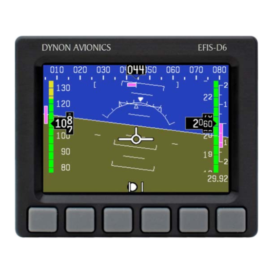
- Page 1 EFIS-D6 Installation Guide This product is not approved for installation in type certificated aircraft. P/N 101209-000, Revision A For use with firmware version 1.0 May, 2009 Copyright © 2003-2009 by Dynon Avionics, Inc.
-
Page 3: Contact Information
Contact Information Dynon Avionics, Inc. 19825 141 Place NE Woodinville, WA 98072 Phone: (425) 402-0433 - 7:00 AM – 5:00 PM (Pacific Time) Monday - Friday Fax: (425) 984-1751 Dynon Avionics offers online sales, extensive support, and continually-updated information on its products via its Internet sites: www.dynonavionics.com –Dynon Avionics primary web site;... -
Page 5: Table Of Contents
Appendix A: Instructions for Continued Airworthiness .................... 5-1 Appendix B: Dynon AOA/Pitot Installation and Calibration ..................5-7 Appendix C: Encoder Serial-to-Gray Code Converter Installation ................5-15 Appendix D: Replacing the EFIS-D6 battery pack....................5-18 Appendix E: Upgrading EFIS-D6 to EFIS-D10A ....................5-19 Appendix F: Weights..............................5-20 Appendix G: EFIS-D6 Specifications........................5-20... -
Page 7: Introduction
Information about the operation of this instrument can be found in the EFIS-D6 Pilot’s User Guide. The EFIS-D6 uses solid-state sensor technology to give an accurate and easy-to-understand display. To ensure accuracy in its readings, it is very important that you install the instrument correctly and perform the specified calibration steps. -
Page 8: About This Guide
MORE, then pressing SETUP, and then pressing VRSION to enter the firmware version menu. Note that the MORE button is not shown in the sequence, since pressing MORE reveals more options in the same level of the menu system. EFIS-D6 Installation Guide... -
Page 9: Wiring Overview
Ensure that the power lines include a circuit breaker or an appropriately sized fuse for the wire you select. Power is fed to the EFIS-D6 via pins in the female D-25 connector as shown on the 25-Pin Female EFIS Harness diagram on page 2-2. -
Page 10: 25-Pin Female Efis Harness
Below is the wiring diagram of the EFIS 25-pin female harness. If you purchased your harness from Dynon Avionics, it is color coded according to the chart on the following page. Unless noted otherwise, all wires are 3 feet long on the Dynon-provided harness. EFIS-D6 Installation Guide... - Page 11 Dynon is color-coded. These colors are listed in the following chart. For wires that are marked “(Unused in EFIS-D6)”, terminate these wires in an appropriate manner (insure that they do not short). Dynon recommends not cutting or removing these wires...
- Page 12 The following block diagram depicts the basic layout of the EFIS DB25 electrical connections and is for reference only. Read the specific instructions for each connection prior to installation. The colors shown refer to the Dynon-supplied EFIS harness. EFIS-D6 Installation Guide...
-
Page 13: Instrument Installation
3. INSTRUMENT INSTALLATION This section provides you with the information needed to physically and electrically install the EFIS-D6. While the EFIS-D6 includes a built-in electronic compass, it is recommended to install and calibrate the included EDC-D10A Remote Compass Module. Selecting a Remote Compass Module Location... -
Page 14: Edc-D10A Communication Cable
EDC-D10A Communication Cable DO NOT ATTEMPT TO POWER UP THE EFIS-D6 WITH THE EDC CABLE LEADS EXPOSED (UNSHEATHED) AND NOT INSTALLED IN THE DB9 CONNECTOR. SHORTING THESE CONNECTIONS WILL CAUSE DAMAGE TO THE UNIT. -
Page 15: Power Inputs
Battery power. EFIS Serial Harness The EFIS-D6 has one RS-232 serial port that can be used for two purposes. The EFIS Serial port (DB9) is used for: • Connecting to a PC to use the Dynon Support Program to perform firmware upgrades, configure checklists, and download internal logs. - Page 16 Dynon, obtain a 9-pin D-sub connector and make the three connections shown in the table. To verify proper communication between the EFIS-D6 and the PC, use the Dynon Support Program’s “Detect Firmware Version” function. Download the latest version of the Support Program at downloads.dynonavionics.com.
-
Page 17: Altitude Encoder Wiring
There are four different serial formats used by transponders. The EFIS-D6 can output any of these formats. To select which format the EFIS-D6 sends out its serial encoder output port, you must choose the appropriate format via the menu system. - Page 18 ALT, space, five altitude bytes, carriage return Format ALT 05200[CR] Example message Format 4 Garmin GTX327, GTX328, and GTX330 (set on Icarus Used By input), Icarus, Trimble 9600 Baud rate ALT, space, five altitude bytes, carriage return Format ALT 05200[CR] Example message EFIS-D6 Installation Guide...
-
Page 19: Audio Alert Output
Outside terminal To ground To set the volume of the AOA alarm, you will need your EFIS-D6 powered on and the alarm output wired as described above. Enter the EFIS menu by pressing any button (except the leftmost or rightmost) beneath an EFIS page. Press SETUP > AOAALM. In that menu, press the TEST button. -
Page 20: Panel Location And Mounting
EFIS-D6 square with the direction of flight. You have two options for mounting the EFIS-D6 into your panel: standard or flush. You may use the optional flush-mount bracket, allowing the face of the EFIS-D6 to be flush with your panel. - Page 21 EFIS-D6 and then slide the flush mount bracket over the EFIS-D6. The bracket should wrap around the bezel of the EFIS-D6. Place one of the 4 supplied nuts on each of the 4 studs and tighten the nuts. The EFIS-D6/bracket can now be installed from behind your panel using the #6 screws through the previously drilled holes.
-
Page 22: Connecting Static & Pitot Lines
If you purchased Dynon’s AOA pitot tube, note that it has pitot and AOA ports on it, but not static. You will need to provide your own source of static pressure for the EFIS-D6 and any other instrument in your panel which requires it. -
Page 23: Efis Calibration And Configuration
To account for your individual preferences and your aircraft’s particular setup, there are a few simple calibration and configuration steps that you must complete before using your EFIS-D6. This section takes you through these steps to make sure that you have properly installed and configured your EFIS-D6. - Page 24 Magnetic Field Values” button at the bottom of the linked page – the values required by your Dynon EFIS will be displayed only after clicking that button. Entering inclination and intensity into the EFIS-D6 1. Enter the inclination setup menu by pressing any button beneath an EFIS page (except the far left or far right hotkeys), then SETUP >...
- Page 25 Once you have the installation completed, have verified that your EDC-D10A communicates with the EFIS-D6 (i.e., heading tape is displayed at the top of the screen), and have located a suitable place to perform the calibration, perform the following steps: 1.
- Page 26 North such as on a compass rose. You must also have enough room to perform a 540 turn on the ground as described below. Turn the EFIS-D6 on and let it warm up for 10-15 minutes before proceeding. Turn all instruments on that you would normally be operating during a flight, including the engine.
- Page 27 EFIS Calibration and Configuration During magnetic calibration, do not turn the power off on the EFIS-D6. This will cause any recorded compass calibration data to be lost; the calibration will need to be restarted. 1. Enter the EFIS calibration menu by pressing any button beneath an EFIS page, then SETUP >...
- Page 28 Dynon Avionics EDC-D10A Remote Compass. You will need to repeat this process anytime you move the EFIS-D6 to a new location in your plane or change the magnetic or electrical characteristics of the nearby environment (i.e. adding or removing other electrical instruments).
-
Page 29: Configure Airspeed Color Thresholds
2. Press DEC- or INC+ to decrement or increment the selected digit. 3. Press BACK to return to the previous menu. You will not be able to see some of the colors until the aircraft has achieved airspeeds in the range of each threshold. EFIS-D6 Installation Guide... -
Page 31: Appendix
INTERNAL BATTERY CHECK If your EFIS-D6 has a rechargeable Internal Backup Battery, it is necessary to ensure that the battery capacity is such that it will last at least 2 hours on a full charge. At least once per year, perform the following test. - Page 32 4. Let the unit remain on for 2 hours. 5. If, after these 2 hours, your EFIS-D6 has not turned off and does not display the INTERNAL BATTERY LOW warning, your battery passes the capacity test. 6. Make sure you recharge your battery; a full charge is reached when the voltmeter shows at least 16.0 volts on the internal battery.
- Page 33 This is most common in unventilated panels during hot periods. If you continue to see this alert, provide more airflow to the space around the EFIS-D6. EFIS-D6 Installation Guide...
- Page 34 EDC-D10A. TROUBLESHOOTING GUIDE The following table provides a list of potential issues that the EFIS-D6 may experience. The symptom is given on the left side while the probable solution is listed at the right. You may also post about your issue at forum.dynonavionics.com, where we and other active users may be able...
- Page 35 INSTRUCTIONS FOR RETURN If none of the above sections have helped resolve an ongoing issue with your EFIS-D6, please contact Dynon Avionics to discuss the issue with Technical Support. If, after troubleshooting with a Dynon representative, the issue cannot be resolved, we will provide you with a Return Material Authorization (RMA) number to use when shipping the EFIS-D6 to us.
- Page 36 Appendix We recommend that you also send your EDC-D10A remote compass along with your EFIS-D6. This ensures that if we upgrade the firmware in your EFIS-D6, the EDC-D10A will have corresponding firmware. While Dynon Avionics makes every effort to save and restore your unit’s settings and calibrations, we cannot guarantee that this will happen.
-
Page 37: Appendix B: Dynon Aoa/Pitot Installation And Calibration
The second pressure port is located on an angled surface just under the pitot port and is designed to be very sensitive to AOA. The EFIS-D6 then uses the difference between these two pressures to calculate the current angle of attack. - Page 38 Appendix • Two plumbing lines (usually ¼” soft aluminum or plastic tubing) routed from the EFIS-D6 to the probe mounting location. • Adapters to interface with the 3/16” aluminum tubing from the probe to whatever plumbing lines are installed in the aircraft (AN919-2D for 3/16 to ¼ , AN819-4D sleeve AN818-4D nut, AN819-3D sleeve, and AN818-3D nut) •...
- Page 39 Appendix instructions on the following pages. Read the specific instructions for each connection prior to installation. EFIS-D6 Installation Guide...
- Page 40 The switch allows you to manually turn the more than 1 amp. Current depends on heater controller on and off, depending on light source connected. the situation. Install a 15-amp fuse at any point along the power line to the heater 5-10 EFIS-D6 Installation Guide...
- Page 41 Drill and tap mounting holes (#6- 32) on the probe to match your mounting bracket. Use caution when drilling the holes, ensuring that you avoid drilling into the pitot and AOA pressure lines. As long as you do not penetrate EFIS-D6 Installation Guide 5-11...
- Page 42 Appendix these lines, you may drill all the way through the outer metal without affecting the probe’s waterproofing. DIMENSIONS Standard mount 5-12 EFIS-D6 Installation Guide...
- Page 43 Make gentle bends, and only bend any given section once. After mounting the probe, route the pitot and AOA lines from the probe to your EFIS-D6. The tube closest to the snout is the pitot line, while the tube in the rear is the AOA line. There is no static source on the probe.
- Page 44 Anytime airspeed is below the MINSPD value, AOA alarms will not occur; anytime it is above the MINSPD value, alarms can occur. If the AOA alarm is already sounding as airspeed falls below this threshold, it will continue to sound until the high AOA condition is resolved. 5-14 EFIS-D6 Installation Guide...
-
Page 45: Appendix C: Encoder Serial-To-Gray Code Converter Installation
EFIS-D6 and outputs standard Mode-C parallel Gray code into your Mode-C transponder. This Encoder Converter requires data from the EFIS-D6 and is not to be confused with other standalone encoders available on the market. While the installation is not complex, it is important that you install the unit correctly. - Page 46 Ground, which are green (or red) and black respectively, and 2 feet in length. Connect these wires to the EFIS-D6 25-pin female harness. Ensure that your EFIS-D6 is powered off. Then connect the black EFIS Ground wire to pin 21. Then, connect the green wire to pin 13 (Serial Encoder Transmit) on the EFIS harness.
- Page 47 Black Serial Encoder Ground STEP 3: EFIS-D6 ENCODER FORMAT For proper communication the EFIS Altitude Encoder format must be set to format number one. To change this setting, from the main menu, select: SETUP > ALTENC. Press FRMAT until it reads “1.”...
-
Page 48: Appendix D: Replacing The Efis-D6 Battery Pack
Appendix Appendix D: Replacing the EFIS-D6 battery pack 1. Remove the three 7/64” hex screws from the battery door of the EFIS-D6. Do not remove the Phillips or D-sub screws. Screw 3 Screw 1 Screw 2 2. If you previously had a battery, disconnect it from the EFIS-D6 by unplugging the battery connector and gently pulling out old battery. -
Page 49: Appendix E: Upgrading Efis-D6 To Efis-D10A
Appendix E: Upgrading EFIS-D6 to EFIS-D10A The EFIS-D6 is Dynon’s simple, more affordable version of Dynon’s full-featured EFIS-D10A. Your EFIS-D6 can be upgraded to the feature set of the EFIS-D10A, which provides the following features and more: • HSI Capability •... -
Page 50: Appendix F: Weights
The following are the weights of the EFIS-D6 and associated Dynon-supplied sensors. EFIS-D6 ......................1 lb 9 oz (0.709 kg) EFIS-D6 + battery....................1 lb 15 oz (0.879 kg) EFIS 25-pin wiring harness ................... 11.2 oz (0.32 kg) EDC-D10A ......................3.6 oz (0.102 kg) EFIS OAT ........................3.2 oz (0.08 kg)
Need help?
Do you have a question about the EFIS-D6 and is the answer not in the manual?
Questions and answers