
Related Manuals for Dynon Avionics SkyView HDX Series


Summary of Contents for Dynon Avionics SkyView HDX Series
- Page 1 HDX System General Maintenance Manual includes Instructions for Continued Airworthiness 103221-000 Revision F 12/18/2019 Copyright © 2019 by Dynon Avionics, Inc. Dynon Avionics grants third parties' permission to print this document...
- Page 2 Contact Information Dynon Avionics, Inc. 19825 141st Place NE Woodinville, WA 98072 Phone: 425-402-0433 Business Operations: 8:00 AM - 5:00 PM (Pacific Time) Monday - Friday Technical Support Operations: 7:00 AM - 4:00 PM (Pacific Time) Monday - Friday Email Sales: sales@dynoncertified.com Email Support: support@dynoncertified.com...
- Page 3 Revision History Date Approved Description of Change 03/05/2018 Initial Release • 08/25/2018 Added information supporting the following components: o Second Display o HDX-800 o VHF COM o Autopilot Panel o Knob Panel • Moved Autopilot Servo Removal and Installation content to airplane- specific document(s).
- Page 4 • System Description and Operation (Section 2) split into 3 sections (now Section 4: Functional Description and Operation, Section 5: Major Display Functions, Section 6: System Components). • Section 4.4 Function Control Menu and Section 4.5: Setup Menus created to better detail menu usage. •...
- Page 5 References Document Title 103272-000 SkyView HDX System Cert Aircraft Flight Manual Supplement 102949-003 SkyView HDX Pilot’s User Guide 103261-000 SkyView HDX System Installation Manual 43.13-1B Acceptable Methods, Techniques and Practices - Aircraft Inspection and Repair 43.13-2B Acceptable Methods, Techniques and Practices - Aircraft Alterations SkyView HDX System General Maintenance Manual, Revision F Page | v...
-
Page 6: Table Of Contents
Table of Contents Airworthiness Limitations ..............10 Introduction .................... 11 Document Introduction ....................11 SkyView HDX System Overview ............12 System Functions ....................... 15 EFIS-D10A Standby Display ..................16 Functional Description and Operation ..........17 SkyView HDX Displays ....................17 Display Designations and Content ................ - Page 7 SV-MAG-236 Remote Magnetometer................. 44 OAT Sensor ........................ 44 SV-GPS-2020 GPS Antenna/Receiver ............... 45 SV-XPNDR-261 Transponder ..................46 SV-ADSB-472 ADS-B IN Receiver ................46 SV-EMS-220 EMS Module ..................47 6.10 SV-COM-X25/X83 COM Radio Control Panel & Transceiver ........51 6.11 SV-ARINC-429 ARINC 429 Connection Module ............52 6.12 SV-KNOB-PANEL Knob Control Panel ..............
- Page 8 SV-HDX1100 & SV-HDX800 Displays................ 82 SV-ADAHRS-200 ADAHRS Module ................84 SV-OAT-340 OAT Sensor ..................85 SV-MAG-236 Remote Magnetometer................. 87 SV-GPS-2020 GPS Antenna/Receiver ............... 88 SV-BAT-320 Backup Battery ..................89 8.10 EFIS-D10A Standby Display ..................90 8.11 EFIS-D10A Backup Battery ..................91 8.12 SV-EMS-220 EMS Module ..................
- Page 9 Transponder Tests ....................122 9.10 Compass Calibration ....................123 Appendix 1: Glossary ................127 SkyView HDX System General Maintenance Manual, Revision F Page | ix...
-
Page 10: Airworthiness Limitations
1 Airworthiness Limitations There are no new or additional Airworthiness Limitations associated with this equipment and/or installation as defined in 14 CFR § 23, Appendix G. G23.4 that result from this modification. The Airworthiness Limitations Section is FAA-approved and specifies maintenance required under 14 CFR §43.16 and §91.403 of the Federal Aviation Regulations unless an alternative program has been approved by the FAA. -
Page 11: Introduction
2 Introduction This document provides Instructions for Continued Airworthiness for use by authorized personnel to maintain the Dynon SkyView HDX System according to Federal Aviation Regulation (FAR) 14 CFR § 23.1529 and 14 CFR 23 Appendix G. Document Introduction The following outline describes the organization of this manual: •... -
Page 12: Skyview Hdx System Overview
3 SkyView HDX System Overview A Skyview HDX System is an integrated Electronic Flight Instrument System (EFIS) that aggregates air, engine, traffic, and navigation information for display to the pilot. The information is presented on a primary SkyView HDX display, which is an LCD touchscreen with mechanical knobs and buttons. - Page 13 Figure 1: Overview of SkyView HDX System, Part 1 SkyView HDX System General Maintenance Manual, Revision F Page | 13...
- Page 14 Figure 2: Overview of SkyView HDX System, Part 2 Page | 14 SkyView HDX System General Maintenance Manual, Revision F...
-
Page 15: System Functions
System Functions This section is an overview of the functions of the SkyView HDX system. For detailed information on operational use and configuration of the system, please refer to the SkyView HDX Airplane Flight Manual Supplement and the SkyView HDX System Installation Manual documents. Required Functions: •... -
Page 16: Efis-D10A Standby Display
EFIS-D10A Standby Display In the SkyView HDX system, the EFIS-D10A (see Figure 3) serves as a backup Altitude, Attitude, and Airspeed indicator in the event of a SkyView HDX Display failure or loss of power. The flight instruments on EFIS-D10A display are generated using internal calibrated sensors. Figure 3 EFIS-D10A Standby Display Page | 16 SkyView HDX System General Maintenance Manual, Revision F... -
Page 17: Functional Description And Operation
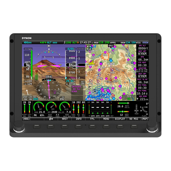
4 Functional Description and Operation This section provides an overview of the major functions and operation of a SkyView HDX System. SkyView HDX Displays SkyView HDX displays are multi-functional, high-definition, LCD color displays that present integrated Primary Flight Information (PFI), NAV/GPS information, Moving Map, COM radio information and control, Transponder information and control, ADS-B IN and OUT, Engine Monitoring, and Autopilot information and control. - Page 18 SkyView HDX display contains three main screen regions, described from top to bottom: • The Top Bar (i.e., Info Bar) is configurable and presents important airplane information, including clock time or a timer (when running), Autopilot status, Backup Battery status, COM radio frequency, and Transponder status.
-
Page 19: Display Designations And Content
Display Designations and Content A SkyView HDX display can present many types and combinations of information. The display designated as the primary display will always present Primary Content. The primary display can also be configured to present Optional Content. Secondary displays can be configured to present any type of information. -
Page 20: Buttons And Knobs
Buttons and Knobs The buttons and knobs on a SkyView HDX display are used for various functions, including powering the unit ON and OFF, accessing and navigating menus, selecting or activating features, and adjusting values. Buttons generally require a single action (i.e., momentarily press). Pressing the button will provide a distinct tactile click response to the pilot. -
Page 21: Function Control Menu
Function Control Menu A SkyView HDX display has a Function Control Menu (i.e. MENU) for controlling various system functions (see Figure 8). To access the MENU, press Button #7. The icons in MENU are tactile and touching them opens the Control Page for the function. For example, touching the COM RADIO icon opens its Control Page (see Figure 9). - Page 22 Figure 9: COM RADIO Control Menu Page | 22 SkyView HDX System General Maintenance Manual, Revision F...
-
Page 23: Setup Menus
Setup Menus Setup Menu and In-Flight Setup Menu are used for controlling the overall configuration, calibration, and behavior of a SkyView HDX System. Information about configuring and calibrating a SkyView HDX System is available in the SkyView HDX System General Installation Manual document. - Page 24 Figure 11: IN FLIGHT SETUP MENU Page | 24 SkyView HDX System General Maintenance Manual, Revision F...
-
Page 25: Major Display Functions
5 Major Display Functions This section provides an overview of the major functions on the SkyView HDX Display. Primary Flight Display Figure 12 for an example Primary Flight Display (PFD) of a SkyView HDX display. PFD includes Airspeed, Altitude, Attitude, Wind, and Navigation information. It can be set to either 100% or 50% page layout, and it will always be presented on the display designated as primary (i.e., the pilot’s display). -
Page 26: Attitude Indicator
Attitude Indicator The Attitude function is a gyro-style indicator (see Figure 13) that appears on the top center of 12). The Attitude Indicator shows the pilot the airplane’s orientation relative the PFD (see Figure to the horizon. Data from the ADAHRS module is used to present the Attitude Indicator on a SkyView HDX display. -
Page 27: Altitude Indicator
Altitude Indicator The Altitude function is a tape-style indicator (See Figure 14) that appears on the right of the PFD (see Figure 12). The Altitude Indicator tells the pilot the barometric altitude of the airplane. The pilot can set an altitude bug using a knob. The bug appears on top of (numerically) and inside (graphically) the indicator. -
Page 28: Airspeed Indicator
Airspeed Indicator The airspeed function is a tape-style indicator (see Figure 15) that appears on the left of the PFD (see Figure 12). The Airspeed Indicator shows the pilot the Indicated Air Speed (IAS) of the airplane in knots or MPH. The pilot can set an airspeed bug using a knob. The bug appears on top of (numerically) and inside (graphically) the indicator. -
Page 29: Vertical Airspeed Indicator
Vertical Airspeed Indicator The vertical airspeed function is a tape-style indicator (see Figure 16) that appears on the far right of the PFD (see Figure 12). The Vertical Airspeed Indicator tells the pilot whether the airplane is climbing/descending (in FPM) or level in flight. The pilot can set a vertical speed bug using a knob. -
Page 30: Horizontal Situation Indicator
Horizontal Situation Indicator The Horizontal Situation Indicator (HSI) is a compass-style indicator (see Figure 17) that appears 12). The HSI shows the pilot the airplane’s course, on the bottom center of the PFD (see Figure heading (HDG), or track (TRK) when using Autopilot Track Mode. The pilot can set the HDG/TRK target value and indicator bug using the HDG/TRK knob. -
Page 31: Wind Indicator
Wind Indicator The wind indicator appears on the bottom left corner of the PFD (see Figure 12). Data provided by the ADAHRS module, Remote Magnetometer, and GPS Antenna/Receiver are used to present the Wind Indicator on a SkyView HDX display. Navigation Source Indicator The selected (current) navigation source appears on the right side of the PDF, just below the Altitude Indicator (see... -
Page 32: Synthetic Vision
5.11 Synthetic Vision A SkyView HDX display provides a synthetic vision representation of the local terrain and obstacles. This display is for advisory purposes only and must not be used as the sole means of terrain and obstacle avoidance. When enabled, terrain clearance advisories are provided based on the predicted path of the airplane relative to the terrain database and the proximity of the aircraft to terrain. -
Page 33: Moving Map & Vfr Gps Navigator
5.12 Moving Map & VFR GPS Navigator A SkyView HDX display uses navigation databases (i.e. terrain, aviation, obstacle, and base) and GPS-derived airplane position data to present the Moving Map (see Figure 18) and Navigation (see Figure 19) and Flight Planning (see Figure 20) functions. - Page 34 Figure 19: Navigation Info in Split-Screen (50%) Layout Figure 20: Flight Plan in Split-Screen (50%) Layout Page | 34 SkyView HDX System General Maintenance Manual, Revision F...
- Page 35 5.12.1 Navigation Databases and Charts A SkyView HDX System should be kept updated with the latest available databases. Depending on the database, these may be updated as frequently as every month. See the SkyView HDX System General Installation Manual document for information about loading databases. A SkyView HDX display can "geo-map"...
-
Page 36: Warning, Caution, And Message Alerting System
5.13 Warning, Caution, and Message Alerting System The area directly above the rightmost button (Button #8) is the Message Notification Area (see Figure 21). This area is reserved to notify the flight crew of various messages and alerts that the SkyView HDX Display can present. - Page 37 Figure 22: Un-acknowledged vs Acknowledged Message Appearance Table 1: Warning Alerts DESCRIPTION POSSIBLE CAUSES Contact Dynon technical support. Always have a properly certified ADAHRS CAL CORRUPT mechanic or repair facility remove the unit. The ARINC 429 module, if installed, ARINC-429 OFFLINE is not communicating with the See Section 7.12...
- Page 38 Table 2: Caution Alerts DESCRIPTION POSSIBLE CAUSES The currently active ADAHRS has detected vibration that will affect the ACTV ADAHRS VIBRATION See Section performance of the: G Meter, Autopilot, Attitude indicator The connected ADS-B traffic/weather receiver has failed or ADS-B IN OFFLINE See Section 7.10 is no longer communicating with...
- Page 39 DESCRIPTION POSSIBLE CAUSES POSITION SOURCE Position source (GPS) failure. See Section GPS X FAIL SkyView Network has lost its STANDBY NETWORK ERROR secondary standby network See Section redundancy. TOUCH PANEL FAULT Touch Hardware is currently offline. See Section Altitude is not being sent to the Transponder because it is not XPNDR ALT ENCODER FAIL See Section...
- Page 40 DESCRIPTION POSSIBLE CAUSES The Roll Autopilot servo has stopped communicating with SkyView. ROLL SERVO OFFLINE See Section 7.14.1 This message also displays if Autopilot servos are not receiving power. The Yaw Autopilot servo has stopped communicating with SkyView. YAW SERVO OFFLINE See Section 7.14.1 This message also displays if...
-
Page 41: System Components
6 System Components This section provides an overview of SkyView HDX System Components. EFIS-D10A Standby Display The EFIS-D10A (see Figure 23) is a standby display, providing attitude, airspeed, and altimeter indicators. It serves as a backup display to a SkyView HDX display. Only power and Pitot and Static lines are connected to the EFIS-D10A. -
Page 42: Adahrs-200 Adahrs Module
SV-ADAHRS-200 ADAHRS Module ADAHRS is an acronym for Air Data Attitude Heading Reference System. The Primary Flight Display (PFD) functions on a SkyView HDX display are generated using data from a group of calibrated sensors built into an SV-ADAHRS-200 module (see Figure 25). - Page 43 Internal Remote Rate Accelero GPS Pitot Static AoA Magneto Magneto Functions Sensors meter meter meter Heading (HDG) ✓ ✓ ✓ ✓ ✓ (Remote Magnetometer) Heading (HDG) ✓ ✓ ✓ ✓ ✓ (Magnetometer Fail) Synthetic Vision ✓ ✓ ✓ ✓ ✓ ✓...
-
Page 44: Mag-236 Remote Magnetometer
SV-MAG-236 Remote Magnetometer The SV-MAG-236 remote magnetometer (see Figure 26) is used in SkyView HDX Systems to locate a magnetometer in an area free of magnetic disturbances. Although the SV-ADAHRS-200 module has an integrated magnetometer, it should be installed in an area free of magnetic disturbances while remaining within proximity of the airplane's center of gravity. -
Page 45: Gps-2020 Gps Antenna/Receiver
SV-GPS-2020 GPS Antenna/Receiver The SV-GPS-2020 antenna/receiver (see Figure 28) is externally mounted and specifically designed for use in a SkyView HDX System. It has a much higher refresh rate than common third-party GPD devices, which ensures smooth Moving Map operation. The SV-GPS-2020 is powered by the SkyView HDX display, and it will continue to provide position updates when the SkyView HDX display is operating on backup battery power. -
Page 46: Xpndr-261 Transponder
SV-XPNDR-261 Transponder An SV-XPNDR-261 transponder (see Figure 29) is a Class 1, Technical Standard Ordered (TSO), remote-mounted, Mode-S transponder. It receives TIS-B (U.S. only) and transmits ADS-B Out. The FAA 2020 ADS-B Out Mandate (14 CFR § / FAR 91.227) requires a Class 1 transponder for flight in Class B or Class C airspaces. -
Page 47: Ems-220 Ems Module
SV-EMS-220 EMS Module The engine gauges presented on a SkyView HDX display are generated from data acquired by the SV-EMS-220 Engine Monitoring System (EMS) module (Figure 31) and its connected sensors and inputs. An SV-EMS-220 supports popular four- and six-cylinder engines in single- and dual-engine airplanes. - Page 48 6.9.1 Single-Engine Airplanes There are three display options (Bottom Band, 50% Page, 100% Page) for viewing engine monitoring information on the SkyView HDX Display. The Bottom Band provides the ability to keep the engine display visible along with other required flight information all on one screen. Generic configuration files are available to configure the Bottom Band display.
- Page 49 6.9.2 Twin-Engine Airplanes Due to limited space on the Bottom Bar and 50% Page displays, twin-engine airplanes will require a dedicated display to present EMS information. This is because FAA regulations require this information always be displayed to the pilot. Loading the EMS configuration file for your airplane is required to configure the system for dual EMS modules and the dedicated EMS display.
- Page 50 Figure 35: Typical Twin Engine EMS Presentation in 50% Page Layout Figure 36: Typical Twin Engine EMS Presentation in Bottom Bar Page | 50 SkyView HDX System General Maintenance Manual, Revision F...
-
Page 51: Com-X25/X83 Com Radio Control Panel & Transceiver
6.10 SV-COM-X25/X83 COM Radio Control Panel & Transceiver The SV-COM-X25 is an integrated VHF COM Radio consisting of two components: the SV- COM-PANEL control panel (see Figure 37) and the SV-COM-T25/T8 transceiver (see Figure 38). The control panel is installed on an instrument panel, and the transceiver is installed remotely in the airplane. -
Page 52: Arinc-429 Arinc 429 Connection Module
6.11 SV-ARINC-429 ARINC 429 Connection Module The SV-ARINC-429 module (see Figure 39) allows the SkyView HDX System to connect to advanced third-party GPS Navigators. Figure 39: SV-ARINC-429 6.12 SV-KNOB-PANEL Knob Control Panel The Knob Control Panel is an optional control panel for a SkyView HDX system that provides dedicated function knobs for ALT, BARO, and HDG/TRK bugs. -
Page 53: Autopilot System
6.13 Autopilot System SkyView HDX Autopilot is an optional, digitally controlled two-axis (roll and pitch) or three-axis (roll, pitch, and yaw) servo-activated system that provides flight path control functions to the pilot. The Autopilot can follow a heading by reference to the compass, follow direction over the ground by reference to GPS track information, or navigate according to a CDI when coupled to SkyView HDX’s internal VFR GPS Navigation data, or when coupled to external navigation source providing VOR, localizer, cross track error or GPS navigation data. - Page 54 Table 6: Autopilot Control Modes CONTROL FUNCTIONALITY DESCRIPTION MODE • LEVEL Rolls wings level and simultaneously returns nose to horizon, then holds zero vertical speed. • Turns toward and holds compass heading as selected by HDG/TRK bug. • Turns toward and holds ground track as selected by HDG/TRK bug. •...
- Page 55 6.13.2 Yaw Damper Control The Yaw Damper is engaged independently from the Autopilot and can be engaged when the Autopilot is not engaged. The Yaw Damper control selector appears only on the Autopilot Control Page (see Figure 41). The Yaw Damper control selector will turn green when engaged. The Slip/Skid indicator will also appear green with the letters YD in black when the Yaw Damper is turned ON, and white when the Yaw Damper is turned OFF, as shown in Figure...
- Page 56 6.13.3 SV-AP-APDISC Autopilot Control Panel The SV-AP-PANEL (see Figure 43) is an optional control panel for SkyView HDX Systems with Autopilot that is installed on an instrument panel. It provides dedicated buttons for engaging the Flight Director, Autopilot, and all control modes, including setting up fully coupled approaches, VNAV, IAS Hold, and mode sequencing (provided that IFR navigation sources are installed).
-
Page 57: Net-Hub Network Hub
6.14 SV-NET-HUB Network Hub The SV-NET-HUB network hub (see Figure 46) is an optional accessory that is typically installed behind an instrument panel near SkyView HDX System components, as well as near Autopilot servo installations. The SV-NET-HUB simplifies component connection to the SkyView HDX Network. -
Page 58: Troubleshooting
7 Troubleshooting Identifying Failures If a major failure occurs that prevents SkyView HDX Display from presenting information, it will respond with a Red X and a descriptive label of which input failed. The Red X may overlay the entire page if a data source such as the ADAHRS module fails (see Figure 48). - Page 59 Figure 49: Example of a GPS Antenna/Receiver Failure Figure 50: Example of an EMS Module Failure SkyView HDX System General Maintenance Manual, Revision F Page | 59...
-
Page 60: Hdx1100 & Sv-Hdx800 Displays
Figure 51: Example of an EMS Sensor Failure SV-HDX1100 & SV-HDX800 Displays If troubleshooting requires accessing or removing the SkyView HDX Display, refer to Section 8.4. 7.2.1 Blank Screen 1. Verify airplane has power. 2. Make sure Master Switch is ON. (If Backup Battery is connected, the SkyView HDX Display should power up regardless of switch position.) 3. -
Page 61: Adahrs-200 Adahrs Module
7.2.2 Fault Messages Messages: CPU TEMP CRITICAL or CPU TEMP HIGH: 1. Access rear of SkyView HDX Display (see Section 8.4.1). 2. Turn unit on and, during bootup, verify both fans in the back of unit are working. 3. If both are not working, contact Dynon technical support. Always have a properly certified mechanic or facility remove unit. - Page 62 If the airspeed indication is a fixed number value and does not change, the pitot sensor and lines may be obstructed. To check for and remove the obstruction, complete the following: 1. Access ADAHRS (see Section 8.5.1). 2. Disconnect Pitot tube from ADAHRS Pitot connection. 3.
- Page 63 7.3.5 No AoA Audio Alerts Normally the AoA probe will produce audible “beeps” as the aircraft approaches a stall. If no AoA audio alerts are heard approaching a stall, perform the following checks: 1. Verify audio is heard for other SkyView HDX Display messages (see Section 7.2.3). If audio is heard for other messages, then there may be a problem with the pneumatic tube from the AoA probe to the ADAHRS module.
-
Page 64: Mag-236 Remote Magnetometer
SV-MAG-236 Remote Magnetometer Message: HDG SOURCE FAIL If the SkyView HDX Display generates this message, the Remote Magnetometer module is not communicating with the SkyView HDX Display. To gain access to the Remote Magnetometer module, see Section 8.7. The Remote Magnetometer module has an LED light to determine its status as follows: •... -
Page 65: Efis-D10A Standby Display
Warning message: B/U BATT LOW CHARGE If the SkyView HDX Display generates this message, perform battery test on each Backup Battery (see Section 9.4). If a Backup Battery is determined to be bad, contact Dynon technical support. Always have a properly rated mechanic or qualified facility remove unit. EFIS-D10A Standby Display The EFIS-D10A includes limited self-diagnostic capability. -
Page 66: Ems-220 Ems Module
SV-EMS-220 EMS Module 7.8.1 Red X Over Entire Engine Display The Engine Monitoring System (EMS) module is not communicating with the SkyView HDX Display. To gain access to the EMS module, see Section 8.12. The EMS module has an LED light to determine its status as follows: •... -
Page 67: Xpndr-261 Transponder
SV-XPNDR-261 Transponder The Transponder includes limited self-diagnostic capability. 7.9.1 Transponder Warnings (Transponder Self Diagnostics) If a fault with the Transponder is detected, a system message will be displayed on the SkyView HDX Display: XPNDR WARNING MESSAGE. To see detailed information on the fault, go to SETUP MENU >... -
Page 68: Adsb-472 Ads-B In Receiver
7.10 SV-ADSB-472 ADS-B IN Receiver If no traffic or weather is appearing on the PFD or Moving Map, the ADS-B IN Receiver is not communicating with the SkyView HDX Display. To gain access to the ADS-B IN Receiver, see Section 8.14. A multicolored LED indicator on the ADS-B IN receiver module confirms hardware operation: •... -
Page 69: Arinc-429 Arinc 429 Connection Module
7.12 SV-ARINC-429 ARINC 429 Connection Module If the SkyView HDX Display is not receiving advanced GPS/NAV data, the ARINC 429 Connection Module is not communicating with the SkyView HDX Display. To gain access to the ARINC 429 Connection Module, see Section 8.18. The ARINC 429 Connection Module has an LED light to determine its status as follows: •... - Page 70 4. Verify electrical power to all servos. 5. Verify adequate ground quality for all servos. If condition persists, or if only one message annunciates: 1. Enter SETUP menu (hold Buttons #7 and #8) 2. Enter SYSTEM SETUP -> SKYVIEW NETWORK SETUP-> NETWORK STATUS 3.
- Page 71 7.14.3 SV-AP-PANEL Autopilot Control Panel If buttons on Autopilot Control Panel do not control Autopilot functions on SkyView HDX Display, complete the following: 1. Access connectors on rear of SkyView HDX Display (see Section 0). 2. Check lights on rear of control panel. The control panel has a LED light to determine its status as follows: a.
-
Page 72: Knob-Panel Knob Control Panel
7.15 SV-KNOB-PANEL Knob Control Panel If the knobs on Knob Control Panel do not control the Barometer (BARO), Altitude (ALT), and Heading/Track (HDG/TRK) functions on SkyView HDX Display, complete the following: 1. Access electrical connectors on rear of SkyView HDX Display (see Section 8.4.1). 2. -
Page 73: Component Removal And Installation
8 Component Removal and Installation This section contains removal and installation instructions for the SkyView HDX system components. It is intended to be used in conjunction with Section 7: Troubleshooting. Equipment Installation Record Per the SkyView HDX System Installation Manual document, a record of the equipment installation, including component locations, installation notes, wiring routing, and drawings, should have been made by the mechanic or facility that installed the SkyView HDX system. - Page 74 Figure 52: Typical Instrument Panel Front View (landscape view) Page | 74 SkyView HDX System General Maintenance Manual, Revision F...
- Page 75 Figure 53: Typical Instrument Panel Rear View (landscape view) SkyView HDX System General Maintenance Manual, Revision F Page | 75...
- Page 76 Figure 54: HDX1100 Avionics Tray Page | 76 SkyView HDX System General Maintenance Manual, Revision F...
- Page 77 Figure 55: HDX800 Avionics Tray SkyView HDX System General Maintenance Manual, Revision F Page | 77...
- Page 78 Figure 56: Remote Module Mounting Tray Page | 78 SkyView HDX System General Maintenance Manual, Revision F...
- Page 79 Table 10: Typical Instrument Panel Mounted Equipment Item Description HDX1100 Primary Display SV-BAT-320 Backup Battery EFIS-D10A Standby Display SV-COM-PANEL COM Radio Control Panel SV-AP-PANEL Autopilot Control Panel SV-KNOB-Panel Knob Control Panel SV-BUTTON-APDISC Autopilot Disconnect Button SV-ARINC-429 ARINC 429 Interface Module SV-ADAHRS-200 ADAHRS SV-EMS-220 Engine Monitoring System SV-ADSB-472 ADS-B Receiver...
-
Page 80: Replacement Hardware
Replacement Hardware The mounting hardware required to install SkyView HDX system components is listed below. Table 11: Replacement Hardware COMPONENT HARDWARE HARDWARE NOTES MODEL NUMBER DESCRIPTION PHILLIPS TRUSS HEAD SV-ADAHRS-200 AN526-832-XX STAINLESS MACHINE OR USE COMPARABLE SCREW 8-32 PHILLIPS TRUSS HEAD SV-BAT-320 AN526-832-XX STAINLESS MACHINE... - Page 81 COMPONENT HARDWARE HARDWARE NOTES MODEL NUMBER DESCRIPTION AN960-8 WASHER OR USE COMPARABLE AN365-832 ELASTIC STOP NUT OR USE COMPARABLE AN3-XX BOLT OR USE COMPARABLE FUEL FLOW AN960-10 WASHER OR USE COMPARABLE SENSOR AN365-1032 ELASTIC STOP NUT OR USE COMPARABLE AN3-XX BOLT OR USE COMPARABLE AMP SENSOR...
-
Page 82: Hdx1100 & Sv-Hdx800 Displays
SV-HDX1100 & SV-HDX800 Displays This section provides removal and installation procedures for the primary and secondary SkyView HDX Displays. Figure 57: SV-HDX110 or SV-HDX800, Front View Figure 58: SV-HDX110 or SV-HDX800, Rear View Page | 82 SkyView HDX System General Maintenance Manual, Revision F... - Page 83 8.4.1 Location Primary display is typically located on left instrument panel; secondary display is typically located on right instrument panel. For specific location, see the Equipment Installation Record document associated with the airplane. 8.4.2 Removal 1. Shut down airplane power. 2.
-
Page 84: Adahrs-200 Adahrs Module
SV-ADAHRS-200 ADAHRS Module This section provides removal and installation procedures for the Air Data Attitude Heading Reference System (ADAHRS) module. Figure 59: SV-ADAHRS-200 8.5.1 Location The ADAHRS unit is typically mounted behind the SkyView HDX Display on the avionics tray. For specific location, see the Equipment Installation Record document associated with the airplane. -
Page 85: Oat-340 Oat Sensor
8.5.3 Installation 1. Install ADAHRS module in same location on avionics tray using same screws (see Table Replacement Hardware if screws need to be replaced). 2. Remove caps from pitot, static, and AoA pneumatic tubes and ports. (If AoA is not installed, AoA port cap remains in place.) 3. - Page 86 8.6.2 Removal 1. Shut down airplane power. 2. Unscrew nylon nut threaded onto OAT sensor inside airplane. 3. Disconnect OAT sensor wiring connector from the ADAHRS module. 4. Remove nylon nut and washer from OAT sensor, and then remove it and wiring from airplane.
-
Page 87: Mag-236 Remote Magnetometer
SV-MAG-236 Remote Magnetometer This section provides removal and installation procedures for the Remote Magnetometer unit. Figure 61: SV-MAG-236 8.7.1 Location For specific location, see the Equipment Installation Record document associated with the airplane. 8.7.2 Removal 1. Shut down airplane power. 2. -
Page 88: Gps-2020 Gps Antenna/Receiver
4. Remove screws that secure Remote Magnetometer module to airplane, and then remove it from airplane. Keep screws for re-installation. 8.7.3 Installation 1. Install Remote Magnetometer module in same location using same screws (see Table Replacement Hardware if screws need to be replaced). 2. -
Page 89: Bat-320 Backup Battery
8.8.3 Installation 1. Install GPS Antenna/Receiver in same location using same screws (see Table Replacement Hardware if screws need to be replaced). To keep moisture from entering the airplane, apply a sealant around the fasteners and holes, as well as the wire pass- through. -
Page 90: Efis-D10A Standby Display
8.9.2 Removal 1. Shut down airplane power. 2. Make sure Skyview HDX system is turned off. 3. Disconnect Backup Battery harness connector. Make sure to protect battery leads from shorting. 4. Remove screws that secure Backup battery to avionics tray, and then remove it from airplane. -
Page 91: Efis-D10A Backup Battery
Figure 64: EFIS-D10A, Drawing, Rear View 8.11 EFIS-D10A Backup Battery This section provides removal and installation procedures for the Backup Battery of the Electronic Flight Instrument System (EFIS) D10A. 8.11.1 Location The Backup Battery is internal to the EFIS-D10A. 8.11.2 Removal If the Backup Battery needs replacement, it can be replaced in the field. -
Page 92: Ems-220 Ems Module
4. Position connector so it is centered on end of battery pack. Verify battery pack is properly centered, not under screw #2. 5. Re-insert screw #2 first and tighten. Screws #1 and #3 are screwed into the extrusion where it is easy to over-tighten and strip the threads. Press on the back plate as you insert screws #1 and #3 and tighten. - Page 93 8.12.3 Installation 1. Install EMS unit in same location using same screws (see Table Replacement Hardware if screws need to be replaced). 2. Re-connect SkyView HDX network connector. 3. Re-connect DB25 and DB37 connectors to EMS module. 4. If necessary, install piggybacked ADAHRS module (see Section 8.5.3). 5.
- Page 94 If your airplane did not originally come equipped with this sensor, refer to the Equipment Installation Record document to see where the sensor is located on your airplane. Removal: To remove the fuel pressure sensor, follow the removal instructions in the airplane or engine manufacturer’s maintenance manuals, or complete the following steps: 1.
- Page 95 8.12.8 Fuel Level Sensor The SV-EMS-220 utilizes the fuel level sensors originally installed in your airplane and are typically located in the airplane’s fuel tanks. Refer to the airplane or engine manufacturer’s maintenance manuals for detailed location information. Removal: To remove the fuel level sensor, follow the removal instructions in the airplane or engine manufacturer’s maintenance manuals.
- Page 96 4. If sensor is not immediately replaced, temporarily cover open boss to prevent system contamination. Installation: To install a CHT sensor, follow the installation instructions in the airplane or engine manufacturer’s maintenance manuals, or complete the following steps: 1. Apply thread sealant to pipe threads. 2.
- Page 97 1. Apply thread sealant to pipe threads. 2. Thread sensor into boss and tighten to prevent gas leak. 3. Connect wiring harness connector to sensor. 4. Conduct an operation test to confirm correct operation and that there are no gas leaks. 8.12.13 Amps Sensor The SV-EMS-220 utilizes an ammeter shunt to sense amps.
- Page 98 on the EMS module wiring harness connect to the magneto control switch as depicted in the 103488-000 - WIRING DIAGRAM, TYPICAL HDX DUAL DISPLAY document. 8.12.16 Manifold Air Pressure Sensor The Manifold Air Pressure (MAP) sensor is typically connected to the engine induction system by a flexible hose.
- Page 99 8.12.17 Flap Position Sensor The SV-EMS-220 utilizes the Flap Position sensor originally installed in your airplane. Refer to your airplane manufacturer’s maintenance manuals for detailed location information. Removal: To remove the Flap Position sensor, follow the removal instructions in the airplane or engine manufacturer’s maintenance manuals.
-
Page 100: Xpndr-261 Transponder
8.13 SV-XPNDR-261 Transponder This section provides removal and installation procedures for the Transponder module. Figure 66: SV-XPNDR-261 8.13.1 Location Typically, the Transponder module is located as close to its antenna as possible. For specific location, see the refer to the SkyView HDX Equipment Installation Record document associated with the airplane. -
Page 101: Adsb-472 Ads-B In Receiver
8.13.2 Removal 1. Shut down airplane power. 2. Remove D25 connector and antenna TNC connector from Transponder module. 3. Release retaining clip that secures Transponder module to tray, and then remove it from airplane. 8.13.3 Installation 1. Install Transponder module into tray and secure with retaining clip. 2. - Page 102 8.14.1 Location The ADS-B IN Receiver is typically located behind the SkyView HDX Display on the avionics tray. For specific location, see the Equipment Installation Record document associated with the airplane. 8.14.2 Removal 1. Shut down airplane power and disconnect the battery. 2.
-
Page 103: Ads-B Antenna
8.15 ADS-B Antenna This section provides removal and installation procedures for the ADS-B Antenna. Since a variety of antennas can be used, the manufacturer’s installation manual is required. Figure 68: ADS-B Antenna 8.15.1 Location The ADS-B Antenna is typically located on the underside of the airplane. For specific location, see the Equipment Installation Record document associated with the airplane. -
Page 104: Com-T25/T8 Com Radio Transceiver
8.16 SV-COM-T25/T8 COM Radio Transceiver This section provides removal and installation procedures for the COM Transceiver. Figure 69: SV-COM-T25 and SV-COM-T8 8.16.1 Location For specific location, see the Equipment Installation Record document associated with the airplane. 8.16.2 Removal 1. Shut down airplane power and disconnect the battery. 2. -
Page 105: Com-Panel Com Radio Control Panel
8.16.3 Installation 1. Install Transceiver into tray and secure with retaining clip. 2. Connect D25 connector and antenna TNC connector to COM Transceiver. 3. Restore power to airplane. 4. Turn SkyView system ON. 5. Verify there are no error messages associated with the COM system. If there is an error message, see Section 7.11. -
Page 106: Arinc-429 Arinc 429 Connection Module
8.17.2 Removal 1. Shut down airplane power and disconnect the battery. 2. Remove screws that secure control panel faceplate to instrument panel. Keep screws for re-installation. 3. Remove control panel and disconnect electrical connectors from control panel. 8.17.3 Installation 1. Connect electrical connectors to control panel, as depicted in the 103488-000 - WIRING DIAGRAM, TYPICAL HDX DUAL DISPLAY document. -
Page 107: Aoa Probe
8.18.2 Removal 1. Shut down airplane power and disconnect the battery. 2. Remove D9 and D25 connectors from ARINC 429 Connection Module. 3. Remove screws that secure ARINC 429 Connection Module to avionics tray, and then remove it. Keep screws for re-installation. 8.18.3 Installation 1. -
Page 108: Autopilot Servos
NOTE: Because the pitot and AoA plumbing lines have not been annealed, they work- harden rapidly when manipulated. Make gentle bends, and only bend any given section once. 3. Remove screws that secure AoA Probe to mounting mast. Keep screws for re-installation. 4. -
Page 109: Ap-Panel Autopilot Control Panel
8.21 SV-AP-PANEL Autopilot Control Panel The Autopilot Control Panel is an optional control panel that can be oriented horizontally or vertically to give the pilot easier access to the SkyView HDX Autopilot. The Autopilot controls are still accessible through the SkyView HDX Display menu buttons after installation of the Autopilot Control Panel. -
Page 110: Button-Level Autopilot Level Button
8.21.3 Installation 1. Connect electrical connectors to control panel. 2. Install control panel in same location on instrument panel using same screws (see Table Replacement Hardware if screws need to be replaced). 3. Restore power to airplane. 4. Turn SkyView system ON. 5. -
Page 111: Button-Apdisc Autopilot Disconnect Button
8.22.3 Installation 1. Connect electrical connector to button. 2. Install button in same location on instrument panel using same screws (see Table Replacement Hardware if screws need to be replaced). 3. Restore power to airplane. 4. Turn SkyView system ON. 5. -
Page 112: Yoke-Mount Autopilot Disconnect Button
8.23.3 Installation 1. Connect electrical connector to button. 2. Install button in same location on instrument panel using same screws (see Table Replacement Hardware if screws need to be replaced). 3. Restore power to airplane. 4. Turn SkyView system ON. 5. -
Page 113: Knob-Panel Knob Control Panel
8.25 SV-KNOB-PANEL Knob Control Panel This section provides removal and installation procedures for the Knob Control Panel. It is an optional control panel that can be oriented horizontally or vertically. Figure 77: SV-KNOB-PANEL 8.25.1 Location The Knob Control Panel is typically located on the left instrument panel to the right of the SkyView HDX Display. -
Page 114: Panel Mount Usb Port
8.25.3 Installation 1. Connect electrical connectors to control panel. 2. Install control panel in same location on instrument panel using same screws (see Table Replacement Hardware if screws need to be replaced). 3. Restore power to airplane. 4. Turn SkyView system ON. 5. -
Page 115: Servicing
9 Servicing The Skyview HDX system does not require special servicing. In the event of system failures, contact Dynon technical support. Always have a properly rated mechanic or qualified facility remove a failed component. Periodic Maintenance The Skyview HDX system components are designed to detect internal failures. A thorough self- test is performed upon application of power to the components, and BITs (Built-In Tests) are continuously executed. - Page 116 ITEM DESCRIPTION / PROCEDURE INTERVAL Display Backlight 8) On SkyView HDX Display or EFIS-D10A Standby Display, the On condition or every 24 backlight lamp may dim over time, and the display may not calendar months. perform as well in direct sunlight conditions. User must determine 10) Always have a properly by observation when the display brightness is not suitable for rated mechanic or...
-
Page 117: Updating Skyview Hdx System Software
ITEM DESCRIPTION / PROCEDURE INTERVAL • OAT Probe: Visually inspect OAT probe for damage and wear. The OAT wiring should be checked for integrity, damage, chafing, or excessive wear. The installation should be inspected for cracks in the fuselage, and loose, or damaged fasteners. -
Page 118: Updating Aviation Databases And Charts
5. Update software by pressing UPDATE, or press CANCEL to return to the SYSTEM SOFTWARE Menu. 6. Go to SETUP MENU > SYSTEM SETUP > SKYVIEW NETWORK SETUP > NETWORK STATUS and confirm software version is correct per Figure 29) Updating the software on a SkyView HDX Display automatically updates all the modules connected on the same SkyView HDX network;... -
Page 119: Skyview Hdx System Backup Battery Test
4. Select a file and press LOAD. NOTE: Press REMOVE to delete old files from USB flash drive. 5. Once loaded, go to SETUP MENU > LOCAL DISPLAY SETUP > INSTALLED DATABASES to verify databases and charts are current (see Figure 81). -
Page 120: Efis-D10A Backup Battery Test
32) This test discharges the Backup Battery. Recharging the Backup Battery after the test is recommended by flying for approximately four hours or by powering on SkyView HDX Display with ground power greater than 12.25 volts for approximately four hours. EFIS-D10A Backup Battery Test The internal backup battery must be tested once every 12 months to ensure it is operational and meets the nominal 45-minute expected backup operation period. -
Page 121: Pitot/Static Leakage Test
Pitot/Static Leakage Test This test must be done to make sure there are no leaks in the pitot or static pneumatic tubes. The check needs to be performed anytime the pitot and static pneumatic tubes are removed from the ADAHRS module or the EFIS-D10A Standby Display. This test must be used when performing pitot/static, transponder, or other tests that manipulate either the pitot or static pressures. -
Page 122: Zero Pressure Ias/Aoa Calibration
Zero Pressure IAS/AoA Calibration This calibration samples pitot, static, and AoA pressures. It should be performed before the AoA calibration. Calibration should be performed in a windless environment to allow the SkyView HDX system to provide the best possible Indicated Airspeed (IAS) readings at very low airspeeds. - Page 123 SETUP > AUTO ALT/GND > AUTOMATIC (AIR DATA). In this mode, in the XPNDR menu, the GND button does not appear, and the ALT button will not change mode unless you are in flight. 2. Some aircraft may be equipped with a squat switch for Transponder mode control; before changing AUTO ALT/GND, record which squat switch configuration is set.
- Page 124 3. Enter Setup Menu on SkyView HDX Display and go to Compass Calibration Wizard (SETUP MENU > HARDWARE CALIBRATION > ADAHRS CALIBRATION > COMPASS CALIBRATION). NOTE: GPS data on the Compass Calibration Page must be green. If it is red, GPS data is not valid.
- Page 125 Calibration Procedure: 1. While observing conditions listed above, push Buttons 7 and 8 simultaneously to enter IN-FLIGHT SETUP MENU. 2. Select COMPASS CALIBRATION. 3. Click knob to enter in-flight COMPASS CALIBRATION menu (see Figure 83). Figure 83: In-Flight Compass Calibration Menu 4.
- Page 126 If, after multiple attempts at in-flight compass calibration, you cannot achieve a quality of at least 70, it’s likely the compass sensor in the Remote Magnetometer module cannot sense the earth’s magnetic field with enough precision (excessive magnetic interference). The location of the Remote Magnetometer module should then be changed. Page | 126 SkyView HDX System General Maintenance Manual, Revision F...
- Page 127 10 Appendix 1: Glossary The following abbreviations/acronyms are used within this document: Aircraft Certification Offices (FAA) ADAHRS Air Data, Attitude and Heading Reference System ADS-B Automatic Dependent Surveillance Broadcast AHRS Attitude and Heading Reference System Airplane Evaluation Group (FAA) Altitude Approved Model List Angle of Attack Autopilot...
- Page 128 Global Positioning System GNSS Global Navigation Satellite System Heading Horizontal Situation Indicator Instructions for Continued Airworthiness Instrument Flight Rules Line Replaceable Unit Magnetic Mega-Hertz Navigation Outside Air Temperature Primary Flight Display Supplemental Type Certificate Traffic Information Service Track Technical Standard Order Visual Flight Rules Vertical Speed Indicator XPDR...
Need help?
Do you have a question about the SkyView HDX Series and is the answer not in the manual?
Questions and answers