
Subscribe to Our Youtube Channel
Related Manuals for Bender RCMA421H-DCB


Summary of Contents for Bender RCMA421H-DCB
- Page 1 Manual RCMA421H-DCB WN-35BS Residual current monitor for monitoring AC, DC and pulsed DC currents in earthed and resistance earthed systems Software version D290 V1.0x RCMA421H-DCB_D00062_00_M_XXEN/05.2014...
- Page 2 Bender GmbH & Co. KG P.O. Box 1161 • 35301 Gruenberg • Germany Londorfer Str. 65 • 35305 Gruenberg • Germany Tel.: +49 6401 807-0 Fax: +49 6401 807-259 E-Mail: info@bender.de Web: http://www.bender.de © Bender GmbH & Co. KG All rights reserved.
-
Page 3: Table Of Contents
Table of Contents 1. Making effective use of this document ............5 How to use this manual ................. 5 Intended use ...................... 5 2. Safety instructions ................... 7 General safety instructions ................7 Working on electrical installations ............. 7 Device-specific safety instructions ............. 7 3. - Page 4 5.7.4 Making settings in the SEt menu ............. 23 5.7.5 Querying and erasing the fault memory in the HIS menu ..... 25 6. Technical data ....................27 Data RCMA421H-DCB-2 in table form ........... 27 Error codes ....................... 30 Recommended contactors ................ 32 Response times of the RCMA421H system plus contactor in ac- cordance with UL943 ...................
-
Page 5: Making Effective Use Of This Document
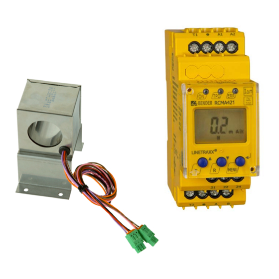
Info symbol. 1.2 Intended use The AC/DC sensitive residual current monitor RCMA421H-DCB with its meas- uring current transformer WN-35BS is used to monitor earthed and resistive earthed systems (TN and TT systems) in which DC and AC fault currents may occur. - Page 6 Making effective use of this document RCMA421H-DCB_D00062_00_M_XXEN/05.2014...
-
Page 7: Safety Instructions
2.1 General safety instructions In addition to these operating instructions, the “Important safety instruction for Bender products”, which are also included in the scope of supply, are an in- tegral part of the device documentation. 2.2 Working on electrical installations Only skilled persons are permitted to carry out the work necessary to ... - Page 8 Safety instructions RCMA421H-DCB_D00062_00_M_XXEN/05.2014...
-
Page 9: Function
3. Function 3.1 Device features AC/DC sensitive residual current monitor with external 35 mm measur- ing current transformer Can be used in conjunction with a UL508-listed contactor Rated residual operating current I = 6 mA to UL943 ... -
Page 10: Description Of Function
Function 3.2 Description of function The RCMA421H-DCB runs a device test when the power supply voltage is con- nected. During the start-up phase, the TRP LED lights up and the alarm relay switches to the alarm setting. Once the device test has been completed suc- cessfully, the ERR alarm LED will stop flashing, the TPD LED will go out and the alarm relay will return to the normal setting. -
Page 11: Quick Query Of The Rated Residual Operating Current
Function alarm LED will flash (error codes E.01 or E.03). Once the error has been elimi- nated, the alarm LEDs and the alarm relay will remain in the alarm state. Press- ing the Reset button R or sending a RESET command via the RS-485 interface will switch K2 back to its initial state and the alarm LEDs will go out. -
Page 12: Malfunction
This interface provides the device with a means of communicating with an alarm indicator and test combination (e.g. MK2430). The ability to output up- to-date measured values and alarms is just one of the features supported. Test and reset commands can be sent to the RCMA421H-DCB from the MK2430. RCMA421H-DCB_D00062_00_M_XXEN/05.2014... -
Page 13: Installation And Connection
4. Installation and connection Make sure that the installation area has been de-energised and ensure compliance with the regulations for working on electri- cal installations. 4.1 Dimension diagrams RCMA421H dimension diagram and drawing for screw fixing The front plate cover is easy to open at the lower part marked by an arrow. RCMA421H-DCB_D00062_00_M_XXEN/05.2014... - Page 14 Installation and connection Dimension diagram for measuring current transformer WN-35BS 51,20 Dimensions in mm RCMA421H-DCB_D00062_00_M_XXEN/05.2014...
- Page 15 Installation and connection 1. Mounting on a DIN rail: Snap the mounting clip at the rear of the device onto the DIN rail so that it sits securely. Screw fixing: Using a tool, position the rear mounting clips (a second mounting clip is required, see the ordering information) so that it protrudes over the enclosure.
-
Page 16: Factory Setting
Installation and connection Conductor colours for measuring current transformer Colour Colour assignment assignment Brown Black Orange Pink Violet 4.2 Factory setting Rated residual operating cur- rent, fixed value: 6 mA Hysteresis, fixed value: Bus address: Bus terminating resistor R: Fault memory M: Permanently activated Mode of operation K2: Permanent... -
Page 17: Operation And Configuration
5. Operation and configuration 5.1 Getting to know the user interface Green Power ON LED: Lights up when the power supply voltage is connected and the device is running. Red TPD alarm LED: Lights up when the rated residual operating current I is exceeded. -
Page 18: Understanding Information On The Standard Display
Operation and configuration 5.2 Understanding information on the standard display Fig. 5.1: Standard display Measured value display in mA: Current type display AC/DC Password protection activated Fault memory activated The actual measured residual current is displayed by default. Press the Up or Down button to display the factory-set rated residual operat- ing current I . - Page 19 Operation and configuration Chapter 5.7 Making settings in the menu onwards, just the relevant button symbol is used to indicate that buttons have been pressed. Button Button symbol Function Call up next display Go to next menu/sub-menu/cate- gory item Activate parameter ...
-
Page 20: Starting A Manual Self-Test
Operation and configuration 5.4 Starting a manual self-test You can start a self-test manually. During the test, any internal malfunctions detected are shown on the display as error codes. The alarm relay will be switched. To start a self-test manually: Press and hold down the test button T (UP) for more than 1.5 seconds. -
Page 21: Making Settings In The Menu
Operation and configuration 5.7 Making settings in the menu 5.7.1 Selecting menus Press and hold down the MENU button for more than 1.5 s to call up the menu. Menus are available for a variety of settings. In turn, each menu has a number of sub-menus. -
Page 22: Querying The Software Version With The Inf Menu
Operation and configuration Menu/Button to call Description/Configurable parameters 4. Press the UP/DOWN buttons to go to the menu. Go to next highest menu level (Back). 5.7.2 Querying the software version with the InF menu 1. Select the InF menu. 2. Confirm with Enter. The software version (e.g. -
Page 23: Making Settings In The Set Menu
Operation and configuration 5.7.4 Making settings in the SEt menu This menu can be used to activate password protection, to modify the pass- word or to deactivate password protection. It is also where the device can be reset to the factory settings. 1. - Page 24 Operation and configuration Change Change/activate/ Change/apply SEt menu Select sub-menu parameter deactivate param. param. value display 3. Deactivate password protection 4. Switch sub- menu 5. Restore factory setting “run” appears on the display and the device is reset to the factory settings automatically.
-
Page 25: Querying And Erasing The Fault Memory In The His Menu
Operation and configuration Change Change/activate/ Change/apply SEt menu Select sub-menu parameter deactivate param. param. value display 7. System menu (is locked) 8. Switch sub- menu 9. Go back to SEt menu 5.7.5 Querying and erasing the fault memory in the HIS menu 1. - Page 26 Operation and configuration HIS menu Error display/Sub-menu 4. Switch error display 5. Erase fault memory 6. Switch error display 7. Go back to HIS menu RCMA421H-DCB_D00062_00_M_XXEN/05.2014...
-
Page 27: Technical Data
6. Technical data 6.1 Data RCMA421H-DCB-2 in table form ( )* = factory setting Insulation coordination to IEC 60664-1/IEC 60664-3 Rated voltage................................250 V Overvoltage category/ pollution degree........................III/3 Rated impulse voltage............................2,5 kV Protective separation (reinforced insulation) between ......... (A1, A2) - (k/l, A/B) - (21, 22, 24) Voltage tests to IEC 61010-1 .......................... - Page 28 Technical data Displays, memories Display range AC/DC measured value ......................0…40 mA Resolution ................................0.1 mA Error of indication 0…20 Hz ..................-33 %…+100 %/± 2 digits Error of indication 20…90 Hz ..................... 0…20%/± 2digits Error of indication 90…150 Hz ....................±17.5%/± 2 digits Error of indication at I <...
- Page 29 Technical data Transport (IEC 60721-3-2)..............2K3 (except condensation and formation of ice) Long-term storage (IEC 60721-3-1)..........1K4 (except condensation and formation of ice) Classification of mechanical conditions acc. to IEC 60721 Stationary use (IEC 60721-3-3) ..........................3M4 Transport (IEC 60721-3-2)............................2M2 Long-term storage (IEC 60721-3-1)........................1M3 Connection For UL application....................
-
Page 30: Error Codes
Technical data Other Operating mode ............................Continuous duty Position of normal use ........................Display-oriented Degree of protection, built-in components (IEC 60529) ..................IP30 Degree of protection, terminals (IEC 60529) ......................IP20 Enclosure material ............................ Polycarbonate Flammability class .............................UL94V-0 Snap-on mounting on a DIN rail ........................IEC 60715 Screw fixing...........................2 x M4 with mounting clip Software version ............................ - Page 31 Action: E… Perform a reset. Restore the device to the factory setting. Should the error persist, contact Bender Service. After removing the CT mains connector, the error code E.03 / E.04 alternately appears on the display. The error code will be erased automatically once the error has been eliminated.
-
Page 32: Recommended Contactors
Technical data 6.3 Recommended contactors The ABB types listed below have undergone performance testing. Auxilary contact Main contact Contactor type A16-30-10-84 A26-30-10-84 A40-30-10-84 A75-30-00-84 A110-30-00-84 A145-30-00-84 A16-30-10-34 A26-30-10-34 A40-30-10-34 A75-30-00-34 A110-30-00-34 A145-30-00-34 A16-40-00-84 A26-40-00-84 A45-40-00-84 A75-40-00-84 EK150* -40-22 A16-40-00-34 A26-40-00-34 A45-40-00-34 A75-40-00-34 EK150** -40-22... -
Page 33: Response Times Of The Rcma421H System Plus Contactor In Ac- Cordance With Ul943
Technical data 6.4 Response times of the RCMA421H system plus contac- tor in accordance with UL943 RCMA421H-DCB_D00062_00_M_XXEN/05.2014... -
Page 34: Ordering Information
External measuring current transformer Type Internal diameter (mm) Art. No. WN-35BS B 9808 0044 RCMA421H-DCB accessories Mounting clip for screw fixing (1 per device).................... B 9806 0008 External alarm indicator and test combination Type Art. No. MK2430A-12: U = AC 18…28 V / DC = 18…30 V B 9510 0006 6.6 Standards, approvals and certifications... -
Page 35: Index
INDEX Accessories 34 HIS menu 25 Assign parameters - Set up or deactivate password pro- Installation and connection 13 tection 23 Instructions for use 5 Bus address, setting 22 Malfunction 12 Button functions 18 Manual, target group 5 Menu, call up 20 Commissioning 16 Menu, exit 20 Conductor colours for measuring current... - Page 36 Response delay t 12 RS-485 interface 15 Self-test, automatic 11 Self-test, manual 11 SEt menu 23 Standards, approvals and certifications 34 Technical data 27 Wiring 15 Working on electrical installations 7 RCMA421H-DCB_D00062_00_M_XXEN/05.2014...
- Page 37 RCMA421H-DCB_D00062_00_M_XXEN/05.2014...
- Page 38 RCMA421H-DCB_D00062_00_M_XXEN/05.2014...
- Page 40 Bender GmbH & Co. KG P.O. Box 1161 • 35301 Gruenberg • Germany Londorfer Str. 65 • 35305 Gruenberg • Germany Tel.: +49 6401 807-0 Fax: +49 6401 807-259 E-Mail: info@bender.de Web: http://www.bender.de...
Need help?
Do you have a question about the RCMA421H-DCB and is the answer not in the manual?
Questions and answers