
Subscribe to Our Youtube Channel
Related Manuals for Balluff BIC 1B0-ITA50-Q40KFU-SM4A4A


Summary of Contents for Balluff BIC 1B0-ITA50-Q40KFU-SM4A4A
- Page 1 BIC 1B0-ITA50-Q40KFU-SM4A4A BIC 1B0-IT005-Q40KFU-SM4A4A BIC 2B0-ITA50-Q40KFU-SM4A5A User´s Guide...
-
Page 2: Table Of Contents
5.2. Connection time Technical data 6.1. Base LED 1 / LED 2 Mechanical data Operating conditions Electrical data Pin Assignment 6.2. Remote LED 1 / LED 2 Mechanical data Electrical data Operating conditions Pin Assignment Order information Ordering information www.balluff.com... -
Page 3: Safety
Balluff IO-Link System BIC 1B0-ITA50-Q40KFU-SM4A4A (Base) BIC 1B0-IT005-Q40KFU-SM4A4A (Base) BIC 2B0-ITA50-Q40KFU-SM4A5A (Remote) Safety 1.1. Installation and Attention! startup Installation and startup are to be performed only by trained specialists. Qualified personnel are persons who are familiar with the installation and operation of the product, and who fulfills the qualifications required for this activity. -
Page 4: Protection From Electromagnetic Fields
It’s possible that for people with active medical implants exist additional limits which can be operational limits. Note In the interest of product improvement, the Balluff GmbH reserves the right to change the specifications of the product and the contents of this manual at any time without notice. -
Page 5: System Overview
The BIC system can only be operated using Balluff IO-Link masters. The reliable operation with IO-Link Master from other manufacturers cannot be guaranteed. If the BIC is connected to a Profibus-IO-Link-Master Module from Balluff, only modules from the following hardware version are allowed. -
Page 6: Installation
Installation 3.1. Mutual To prevent mutual interference with adjacent bases or remotes, the specified minimum Interference distances must be adhered to: A (mm) BIC 1B0-ITA50-Q40KFU-SM4A4A ≥ 70 BIC 2B0-ITA50-Q40KFU-SM4A5A ≥ 70 3.2. Installation in Device damage due to induction effects! metal Metallic objects on and in front of the coil cap will be heated. -
Page 7: Distances / Offset
Balluff IO-Link System BIC 1B0-ITA50-Q40KFU-SM4A4A (Base) BIC 1B0-IT005-Q40KFU-SM4A4A (Base) BIC 2B0-ITA50-Q40KFU-SM4A5A (Remote) Installation 3.3. Distances / offset Permitted distances / offset of the axes Type A (mm) B (mm) BIC 1B0-ITA50-Q40KFU-SM4A4A ≤ 5 ≤ 5 BIC 2B0-ITA50-Q40KFU-SM4A5A ≤ 5 ≤ 5 3.4. -
Page 8: 180° Rotation Of The Connector Insert
Loosen the two countersunk screws Remove the BIC base Pull out the safety pin Slide out the connector insert 180° rotation of the connector insert Note The disassembly/assembly for rotating the connector can be carried out only 2 times. (construction conditioned) www.balluff.com... -
Page 9: Energy Transfer
Power reduction The base component with the order number BIC0070 (BIC 1B0-ITA50-Q40KFU-SM4A4A) variants reduces power while simultaneously optimizing for faster start-up. Metal objects are heated up easily. -
Page 10: Io-Link Communication
Link master used and its parameter settings also affect the connection time. These variables are all application-specific and therefore cannot be generalized. The measurements carried out by Balluff to determine the connection time were done using a Balluff EtherNet-IP master in combination with the Balluff IO-Link device “BNI IOL-302-00-Z012”. -
Page 11: Technical Data
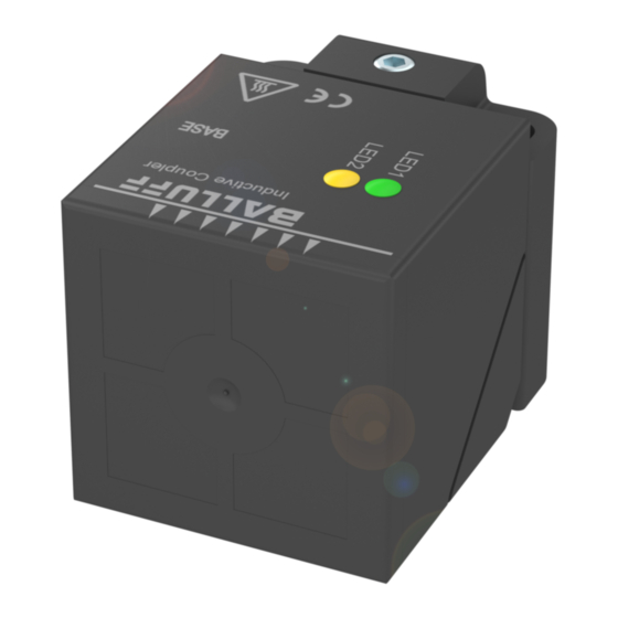
Balluff IO-Link System BIC 1B0-ITA50-Q40KFU-SM4A4A (Base) BIC 1B0-IT005-Q40KFU-SM4A4A (Base) BIC 2B0-ITA50-Q40KFU-SM4A5A (Remote) Technical data 6.1. Base LED 1 / LED 2 Display Function Green static Supply voltage OK LED 1 Green inverted flashing IO-Link connection OK Yellow flashing No Remote found... -
Page 12: Electrical Data
Supply voltage 24 V DC ±10%, by EN 61131-2 Current consumption < 1,4 A Standby current ≤ 200 mA Overload protection Ripple < 1% Pin Assignment Power (M12, 4-pin socket) Signal +24 V Transparent input GND, 0V C/Q, IO-Link www.balluff.com... -
Page 13: Remote
Balluff IO-Link System BIC 1B0-ITA50-Q40KFU-SM4A4A (Base) BIC 1B0-IT005-Q40KFU-SM4A4A (Base) BIC 2B0-ITA50-Q40KFU-SM4A5A (Remote) Technical data 6.2. Remote LED 1 / LED 2 Display Function Green static Supply voltage OK LED 1 Green inverted flashing IO-Link connection OK Yellow on Pin 2 high... -
Page 14: Pin Assignment
Technical data Pin Assignment Power (M12, 5-pin connector) Signal +24 V Transparent output GND, 0V C/Q, IO-Link www.balluff.com... -
Page 15: Order Information
Balluff IO-Link System BIC 1B0-ITA50-Q40KFU-SM4A4A (Base) BIC 1B0-IT005-Q40KFU-SM4A4A (Base) BIC 2B0-ITA50-Q40KFU-SM4A5A (Remote) Order information Ordering Product ordering code Ordering code information BIC 1B0-ITA50-Q40KFU-SM4A4A BIC0070 BIC 1B0-IT005-Q40KFU-SM4A4A BIC0072 BIC 2B0-ITA50-Q40KFU-SM4A5A BIC0071 www.balluff.com... - Page 16 Balluff GmbH Schurwaldstrasse 9 73765 Neuhausen a.d.F. Deutschland Tel. +49 7158 173-0 Fax +49 7158 5010 www.balluff.com balluff@balluff.de...
Need help?
Do you have a question about the BIC 1B0-ITA50-Q40KFU-SM4A4A and is the answer not in the manual?
Questions and answers