Table of Contents
Advertisement
Quick Links
Advertisement
Table of Contents

Subscribe to Our Youtube Channel
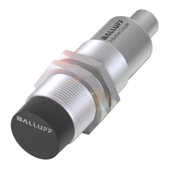
Summary of Contents for Balluff BIC 2I0-IAA50-M30MI3-SM4A5A
- Page 1 BIC IO-Link unidirectional 500 mA, IP67, 11 bytes User´s Guide...
-
Page 2: Table Of Contents
7.1. Dimension 7.2. Mechanical data 7.3. Operating conditions 7.4. Electrical data 7.5. Electrical connections M12, 5-pin, socket IO-Link communication 8.1. Process data IO-Link-communication 8.2. Parameters 8.3. Events Event 1 Event 2 Accessories 9.1. Connectors 9.2. Installation accessories 9.3. Active components www.balluff.com... -
Page 3: Event
Balluff Network Interface Type Designation Code 10.1. Type Code 10.2. Order code www.balluff.com... -
Page 4: User Instructions
User instructions 1.1. Validity of the This manual describes the structure, function and installation of the Balluff Uni IO-Link Guide inductive coupler. It is valid for types: Base BIC 1I0-IAA50-M30MI3-SM4A4A and Remote BIC 2I0-IAA50-M30MI3-SM4A5A Remote BIC 2I0-IAA50-M30MI3-BPX04-002-M45A (see type code) The guide is intended for qualified technical personnel. -
Page 5: Safety
2004/108/EC (EMC) and the EMC law. In our EMC laboratory, which is accredited by DATech for testing electromagnetic compatibility, evidence has been provided that the Balluff products satisfy the EMC requirements of the generic standards: EN 61000-6-4 (Interference emission) and EN 61000-6-2 (Immunity to interference) www.balluff.com... -
Page 6: Construction And Function
If the red LED illuminates and stays on, there is an error in the IO-Link communication. If no device is connected to the remote but the remote is within range of the base, the green LEDs flash. www.balluff.com... -
Page 7: Function Indicator And Diagnosis
Balluff Inductive Coupler Base BIC 1I0-IAA50-M30MI3-SM4A4A and Remote BIC 2I0-IAA50-M30MI3-SM4A5A Remote BIC 2I0-IAA50-M30MI3-BPX04-002-M45A Function indicator and diagnosis 4.1. Base indicators Green LED status indicator "IO-Link Signaling Function Green, static Supply voltage OK No IO-Link communication Green, flashing inversely IO-Link communication between master and base is OK... -
Page 8: Installation And Connection
The spacings specified for installation must be adhered to. To prevent mutual interference with adjacent bases or remotes, the specified minimum distances must be adhered to: Type A (mm) BIC 1I0-IAA50-M30MI3-SM4A4A BIC 2I0-IAA50-M30MI3-SM4A5A BIC 2I0-IAA50-M30MI3-BPX04-002-M45A 5.2. Installation in Attention! Metal Device damage due to induction effects! Metallic objects on the coil cap cause the objects to be heated. -
Page 9: Connection
Legend for graphic: Balluff components Profibus controller Balluff power supply BAE PS-XA-1W-24-050-003 Balluff IO-Link master BNI PBS-502-001-Z001 BIC IO-Link system BIC 1I0-IAA50-M30MI3-SM4A4A BIC 2I0-IAA50-M30MI3-SM4A5A BIC 2I0-IAA50-M30MI3-BPX04-002-M45A Balluff sensor hub BNI IOL-104-000-K006 Balluff sensor hub alternative to 6 BNI IOL-104-000-K021 www.balluff.com... -
Page 10: Technical Data Base
24 V DC +-10%, acc. to EN 61131-2 Operating current at 24 V Max. 1 A Standby current Max. 100 mA Overload protection 6.5. Electrical connection M12, 4-pin, connector Signal Meaning +24 V Input voltage GND, C/Q, IO Link C/Q, IO Link www.balluff.com... -
Page 11: Technical Data Remote
Balluff Inductive Coupler Base BIC 1I0-IAA50-M30MI3-SM4A4A and Remote BIC 2I0-IAA50-M30MI3-SM4A5A Remote BIC 2I0-IAA50-M30MI3-BPX04-002-M45A Technical Data Remote 7.1. Dimension Connector SM4A5A Cable BPX04-002-M45A 7.2. Mechanical data Housing material Brass Degree of protection as per IEC 60529 IP 67 (only in plugged-in and screwed-down state) -
Page 12: Io-Link Communication
Status Meaning "Supply remote" Voltage at the remote is less than 18V "Short remote" Short-circuit at the IO-Link interface of the remote “Inzone” No remote detected “Com” No IO-Link device detected Note Process data update time is max. 200ms www.balluff.com... -
Page 13: Io-Link-Communication
Balluff Inductive Coupler Base BIC 1I0-IAA50-M30MI3-SM4A4A and Remote BIC 2I0-IAA50-M30MI3-SM4A5A Remote BIC 2I0-IAA50-M30MI3-BPX04-002-M45A IO-Link-communication 8.2. Parameters Various base parameters can be accessed via IO-Link. All parameters are read-only, so they involve information, not configuration options. The "Identification data" can contain texts and information about the base. -
Page 14: Accessories
9.2. Installation Description Description Fig. accessories BES 30.0-BS-1 BES 30-HW-1 9.3. Active Description Description Fig. components Profibus connection for base BNI PBS-507-001-Z011 Profibus connection for base BNI PBS-502-001-Z001 Profibus connection for base BNI PBS-504-001-K008 Profinet connection for base BNI PNT-502-105-Z015 www.balluff.com... - Page 15 Balluff Inductive Coupler Base BIC 1I0-IAA50-M30MI3-SM4A4A and Remote BIC 2I0-IAA50-M30MI3-SM4A5A Remote BIC 2I0-IAA50-M30MI3-BPX04-002-M45A Type Designation Code 10.1. Type Code BIC 1I0-IAA50-M30MI3-XXXXXX_002-M45A Balluff inductive Coupler Base (1) Remote (2) Technology (PNP), variant (24 V), power class (500 mA) IA= 11 bytes...
- Page 16 Balluff GmbH Schurwaldstrasse 9 73765 Neuhausen a.d.F. Deutschland Tel.: 07158 173-0 Fax: 07158 5010 www.balluff.com balluff@balluff.de...


Need help?
Do you have a question about the BIC 2I0-IAA50-M30MI3-SM4A5A and is the answer not in the manual?
Questions and answers