Table of Contents
Advertisement
Quick Links
Advertisement
Table of Contents

Related Manuals for Axon Fleet


Summary of Contents for Axon Fleet
- Page 1 Axon Fleet Installation Manual Models AX1001, AX1002, AX1003 IMPORTANT SAFETY INSTRUCTIONS Read all warnings and instructions. Save these Instructions. The most up-to-date warnings and instructions are available at www.axon.com. MMU0065 Rev: E...
-
Page 2: Table Of Contents
Chapter 2: Installation ..........................9 Tools ................................9 Required Tools ............................9 Highly Recommended ........................9 Axon Fleet Power Unit and Axon Signal Vehicle Unit .............. 10 Axon Fleet Power Unit ........................10 Mount/Camera ............................11 Axon Signal Vehicle Unit ........................12 Locate the Vehicle’s Electronics ...................... -
Page 3: Chapter 1: Introduction
The Axon Fleet system consists of the Axon Fleet camera, the Axon Fleet camera mount, and the Axon Fleet power unit. The Axon Fleet power unit is an inline power supply for the camera. During normal operation, the camera is powered by the vehicle;... -
Page 4: Additional Reading
Do not install Axon Fleet components or the Axon Signal Vehicle unit anywhere that will interfere with airbag deployment. Do not install any part of the Axon Fleet system or the Axon Signal Vehicle unit in the vehicle's engine compartment. -
Page 5: Time Requirements
• For training on the View XL software, or how to assign personnel to cameras, recharge your camera, and transfer video from an Axon device to a computer. Visit academy.axon.com. For installation of the router and the antenna, refer to the appropriate manufacturer’s instructions for installation. - Page 6 Two Camera Mounts – SKU 74025 Front view side view Two Axon Fleet Power Units – SKU 74024 One Axon Signal Vehicle Unit – SKU 70112...
-
Page 7: Wiring Harness Assemblies
This dongle is plugged in to a USB port on the vehicle's mobile data terminal (MDT), the in-vehicle Windows laptop computer. The dongle is provided by Axon and enables the MDT to have Bluetooth low-energy (BLE) capabilities. This is required for the MDT to... -
Page 8: Additional Items
Additional Items In addition to the standard Axon Fleet hardware, the agency will need to have a laptop computer, with Axon View XL software installed. Also, a wireless router is required for Wi-Fi or LTE connectivity. Axon recommends and sells a Cradlepoint IBR1100 router. For other options speak to... -
Page 9: Chapter 2: Installation
Chapter 2: Installation Tools The following is a list of required tools to install the Axon Fleet camera system. Required Tools • • Multi-meter to test for voltage Cable ties • • #1 Phillips screwdriver 3M Electrical tape • •... -
Page 10: Axon Fleet Power Unit And Axon Signal Vehicle Unit
Step 1: Determine the Mounting Locations Axon Fleet Power Unit and Axon Signal Vehicle Unit Axon Fleet is installed in typically three different locations. It is important to note the location of the power units, for future reference, in the event the agency needs to locate equipment. -
Page 11: Mount/Camera
Mount/Camera The Axon Fleet mount draws power from the Axon Fleet power unit, and therefore they must be wired together using the 18-foot (5.5 m) wiring harness. Do not mount any of the hardware on the exterior of the vehicle or inside the engine compartment. -
Page 12: Axon Signal Vehicle Unit
For the rear camera, the installer should find a proper location, based on the particular installation. • For the rear camera, Installer can use Axon View XL to find the location that best views the cage area. • For proper adhesion, ensure the rear camera is mounted on a flat surface. -
Page 13: Locate The Vehicle's Electronics
Install the #4 half-inch (12.7 mm) screw to secure the back cover. Locate the Vehicle’s Electronics The next step to installing the Axon Fleet system is locating the wiring for the vehicle. The vehicle make and model will dictate where wiring is found. The installer will need to locate the following wires: 1. -
Page 14: Axon Fleet Power Unit To Camera Mount
Once the appropriate power wires have been run to the power unit mounting location strip no more than 0.25″ (6.35 mm) of insulation from each of the wires. On the Axon Fleet power unit end, remove the male end of the connector. Unscrew the small set screws. -
Page 15: Choose The Appropriate Location
Insert the stripped wires into the appropriate slot on the power unit. • White – 12 • Violet – 9 • Green – 8 • Gray – 7 Tighten down the set screws. Reconnect the male connector to the power unit. Secure the male connector using the small set screws on either end of the connector. - Page 16 Hold the mount in place for 10 seconds to ensure adh Repeat steps 1–5 for the rear camera. • For the rear camera, the installer can use Axon View XL to find the location that best views the cage area. •...
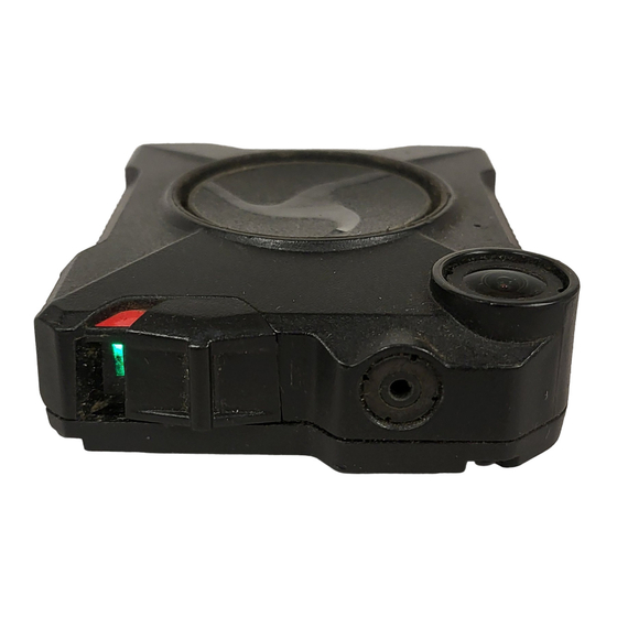
- Page 17 Rear of Axon Fleet system, not installed in a mount The red LED on the Axon Fleet power unit should blink several times and then be solid red after a few seconds. If the red LED continues to blink, there is an...
- Page 18 Once each camera is in BUFFERING mode, test the Axon Signal Vehicle unit, to ensure the desired triggers properly activate the system. For more information, see the Axon Signal Vehicle Unit Installation Manual. • If there are any errors, go to Chapter 3: Troubleshooting.
-
Page 19: Chapter 3: Troubleshooting
Chapter 3: Troubleshooting If the instructions in this chapter do not resolve the issue with your Axon Fleet system, contact customer service at US: 1-800-978-2737 or online at https://www.axon.com/support. Camera will not connect to the Axon View XL program: Ensure the camera is on and in BUFFERING mode. - Page 20 Ensure the camera is properly seated in the mount. Note: In rare cases, the Axon Fleet power unit may be substantially drained and may take 15–20 minutes to charge with the vehicle “on.” The camera should boot when sufficient charge is regained.
-
Page 21: Axon Fleet Installation Worksheet
Axon Fleet Installation Worksheet... -
Page 22: Axon Fleet Hardware Installation Diagram
Axon Fleet Hardware Installation Diagram... - Page 23 Wi-Fi Alliance; and Windows is a trademark of Microsoft Corporation. , AXON, Axon, Axon Fleet, Axon Signal, Axon View XL, Evidence.com, and Evidence Sync, trademarks of Axon Enterprise, Inc., some of which are registered in the US and other countries. For more information, visit www.axon.com/legal.
Need help?
Do you have a question about the Fleet and is the answer not in the manual?
Questions and answers