Advertisement
I NSTA LLAT ION G UI DE
HID Aero™ X1100
Intelligent Controller
Up to 4 Readers, 7 Inputs, 4 Outputs
Supplied parts
ƒ HID Aero X1100 Intelligent Controller (1)
ƒ Installation guide (1)
ƒ Mounting screws (4) 0.138" × 1" (3.5 mm × 25 mm)
ƒ Casing screws (4) 0.118" × 0.75" (3 mm × 20 mm)
Recommended parts
(not supplied)
ƒ Certified DC power supply
ƒ Drill with various bits for mounting hardware
ƒ For DIN rail mounting: Brackets (2) - Phoenix Contact,
USA 10 Series Rail Adapter, part number 1201578.
Screws (4) - Self tapping, countersunk,
3.0 mm × 10 mm (or 3.0 mm × 8 mm)
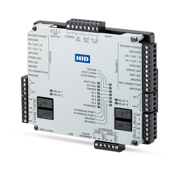
X1100 Overview
The X1100 performs intelligent access control operations, input monitoring and output control for up to:
64 readers, 64 doors, 615 inputs, 388 outputs.
DIP SWITCH
See step 6.
READERS 1-2
See step 4.
"
4.53
(115 mm)
INPUTS 1-4
See step 7.
RELAYS 1-4
See step 5.
© 2019 - 2020 HID Global Corporation/ASSA ABLOY AB. All rights reserved. HID, the HID Brick logo, the Chain Design, HID Aero, and HID Signo are trademarks or registered
trademarks of HID Global, ASSA ABLOY AB, or its affiliate(s) in the US and other countries and may not be used without permission. All other trademarks, service marks, and
product or service names are trademarks or registered trademarks of their respective owners.
hi d gl ob a l.com
CABLE REQUIREMENTS (NOT SUPPLIED)
Host–Ethernet
Readers–OSDP
Readers–
Wiegand / C&D
IO Modules*
Alarm Inputs
Power and Relays
*VertX wire specifications are compatible with X1100. Utilize existing
VertX V100, V200 and V300 RS-485 wiring when attaching to X1100.
POWER, TAMPER, AC FAIL, BATT FAIL
See step 8.
"
5.51
(140 mm)
An ASSA ABLOY Group brand
PLT-04233, Rev. A.3
CAT-5, 328 ft (100 m)
4 conductor twisted pair over-all shield,
Belden 3107A or equivalent. 2000 ft
(610 m) maximum. Utilize one pair for
data and one pair for power
4-conductor, 18 AWG, shielded, 500 ft
(150 m) maximum
One twisted pair, shielded. 120Ω
impedance, 24 AWG, 4,000 ft
(1,219 m) maximum
One twisted pair, 30Ω maximum,
typically 22 AWG, 1000 ft (304.8 m)
2-conductor shielded
18 to 16 AWG, 500 ft (150 m)
Status LEDs
See page 6
READERS 1-2
See step 4.
INPUTS 1-4
See step 7.
RELAYS 1-4
See step 5.
IO MODULE PORTS
See step 3.
Advertisement
Table of Contents

Related Manuals for HID Aero X1100


Summary of Contents for HID Aero X1100
- Page 1 (140 mm) © 2019 - 2020 HID Global Corporation/ASSA ABLOY AB. All rights reserved. HID, the HID Brick logo, the Chain Design, HID Aero, and HID Signo are trademarks or registered trademarks of HID Global, ASSA ABLOY AB, or its affiliate(s) in the US and other countries and may not be used without permission. All other trademarks, service marks, and product or service names are trademarks or registered trademarks of their respective owners.
-
Page 2: Setting The Jumpers
Powering Trusted Identities HID Aero™ X1100 Installation Guide Setting the jumpers 1. If attached, unscrew the four corner casing screws. Battery jumper J4 2. Remove the X1100 casing to access the battery jumper and the end of line termination jumpers. -
Page 3: Connecting Readers
Powering Trusted Identities HID Aero™ X1100 Installation Guide Connecting readers ƒ OSDP (RS-485) signaling requires two 2-conductor Note: For OSDP cable lengths greater than 200 ft cables. One cable for power (18 AWG) and one (61 m) or EMF interference, install 120Ω +/- 2Ω resistor across RS-485 termination ends. -
Page 4: Dip Switch Configuration
Powering Trusted Identities HID Aero™ X1100 Installation Guide Relay circuit wiring DC Strike To DC power source Four relays are provided for controlling door lock RELAY 1 to mechanisms or alarm signaling. RELAY 4 Fuse When controlling the delivery of power to the door strike, the NO (Normally Open) and C (Common) poles are typically used. - Page 5 Powering Trusted Identities HID Aero™ X1100 Installation Guide Input power, cabinet tamper, and UPS fault input wiring The X1100 requires 12-24 V DC power. Connect power TAMPER, AC FAIL, and BATT FAIL connections are with minimum of 18 AWG wire.
-
Page 6: Status Leds
Powering Trusted Identities HID Aero™ X1100 Installation Guide Status LEDs POWER ON SELF-TEST NORMAL OPERATION BATT FAIL On then OFF OFF = Inactive, ON = Active, Flash = Fault.* AC FAIL On then OFF OFF = Inactive, ON = Active, Flash = Fault.*... -
Page 7: Specifications
Powering Trusted Identities HID Aero™ X1100 Installation Guide Specifications AERO X1100 Input Voltage 12 to 24 V DC ±10% Maximum Input Current 1.9 A (550 mA excluding readers and USB) Micro USB Port 5 V DC, 500 mA maximum (reserved for future use) - Page 8 ると電波妨害を引き起こすことがあります。この場合には使用者が適切な 時,可能會造成射頻干擾,在這種情況下, 対策を講ずるよう要求されることがあります。VCCI -A 伊用者會被要求採取某些適嘗的酎策。 Your HID product is marked to indicate its compliance class: ƒ Federal Communications Commission (FCC) – USA ƒ Industry Canada Equipment Standard for Digital Equipment (ICES-003) – Canada ƒ CE Mark – Europe ƒ RCM Mark – New Zealand and Australia ƒ...
Need help?
Do you have a question about the Aero X1100 and is the answer not in the manual?
Questions and answers