Advertisement
Table of Contents
- 1 Packing List
- 2 Install Guide Steps
- 3 Step 5: Remove Nut and Washer from DC Jack. Connect Fan Power Cable to Board (CN15).
- 4 Step 10: Thread the Power Button Cable through the Hole for the Power Button.
- 5 Step 14: Attach 2.5” Drive to Drive Bracket, Secure with Four Screws as Shown.
- 6 Step 17: Wall Mount (Requires Wall Mount Bracket Kit).
- 7 Step 18: Dual COM Port Installation (Optional).
- Download this manual
Quick Installation Guide
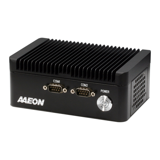
PICO-WHU4-SEMI
This document will guide
you through the basic
installation process for your
new PICO-WHU4-SEMI.
PICO-WHU4-SEMI
Packing
2
1
Item
1
PICO-WHU4 Board (with CMOS battery)
2
System Case
3
SATA Cable
4
SATA Power Cable
5
USB 2.0 Ports/Cable
6
USB Port mounting bracket
7
Power Button
8
4x Screws.M3.Nickel
10x screws.M3.Black
2x Zip Ties (included, optional use)
2x Zip Tie anchors (included, optional use)
9
Dual COM Port/Cable (optional)
10
PICO-WHU4-SEMI VESA bracket kit (optional)
11
PICO-WHU4-SEMI Wallmount bracket kit (optional)
Note: Zip ties and anchors are included for cable management but are not required
to complete the system assembly.
6
8
5
3
4
Description
9
11
User Supplied Components:
7
2.5" SATA Drive (SSD)
144 pin SO-DIMM RAM module up to 32 GB
Remark/PN
170X000101
1702150130
170010010D
M001720000
170010020T
S1D5106010
S1D3004031
1992666607
199266660B
1701200102
PICO-WHU4-SEMI-VESA1
PICO-WHU4-SEMI-WMT1
10
Advertisement
Table of Contents

Related Manuals for Asus AAEON PICO-WHU4-SEMI


Summary of Contents for Asus AAEON PICO-WHU4-SEMI
- Page 1 Quick Installation Guide PICO-WHU4-SEMI This document will guide you through the basic installation process for your new PICO-WHU4-SEMI. PICO-WHU4-SEMI Item Description Remark/PN PICO-WHU4 Board (with CMOS battery) System Case SATA Cable 170X000101 SATA Power Cable 1702150130 USB 2.0 Ports/Cable 170010010D USB Port mounting bracket M001720000 Power Button...
- Page 2 Install Guide Steps PICO-KBU4-SEMI Quick Installation Guide Step 1: Remove the bottom panel of the system case by sliding the panel towards the I/O (rear) side of the system. Step 2: Remove the two screws securing the 2.5” drive bracket. Remove the bracket and set aside. Using a tool, remove the USB 2.0 port punchouts if you haven’t already done so.
- Page 3 Step 5: Remove nut and washer from DC jack. Connect fan power cable to board (CN15). PICO-KBU4-SEMI Quick Installation Guide Step 6: Insert the PICO-WHU4 board into the chassis assembly with the processor side toward the heatsink. DO NOT place the CMOS battery between the board and thermal assembly. Make sure the processor is contacting the thermal padding and the holes line up with board and mounting points.
- Page 4 Step10: Thread the power button cable through the hole for the power button. Button should line up with notch at the top of the hole. Plug the cable into the front panel connector (CN3), then gently push the power button in until it is secure (you will hear a ‘click’). Step 11: Thread USB 2.0 cable into USB bracket.
- Page 5 Step 14: Attach 2.5” drive to drive bracket, secure with four screws as shown. Note orientation with arrow. Attach SATA and SATA Power cables to drive, then attach the assembly to the system (Note: arrow points towards fan). Step 15: To reattach bottom panel, make sure the posts line up with the corresponding slots as shown. Slide panel onto system, then secure with four black screws.
- Page 6 Step 17: Wall Mount (Requires wall mount bracket kit). Line up brackets with the four holes shown. Secure with four black screws. System can now be mounted to wall or surface. Step 18: Dual COM Port installation (optional). Remove I/O punchouts from front of system. Remove the retainer screws from each port connector, four in total.
Need help?
Do you have a question about the AAEON PICO-WHU4-SEMI and is the answer not in the manual?
Questions and answers