Table of Contents
Advertisement
Advertisement
Chapters
Table of Contents

Related Manuals for Asus E394S-IM-AA


Summary of Contents for Asus E394S-IM-AA
- Page 1 E395S-IM-AA E394S-IM-AA E393S-IM-AA User Manual...
- Page 2 Copyright © 2019 ASUSTeK COMPUTER INC. All Rights Reserved. LIMITATION OF LIABILITY Circumstances may arise where because of a default on ASUS’ part or other liability, you are entitled to recover damages from ASUS. In each such instance, regardless of the basis on which you are entitled to claim damages from ASUS, ASUS is liable for no more than damages for bodily injury (including death) and damage to real property and tangible personal property;...
-
Page 3: Table Of Contents
Contents About this manual ......................5 Conventions used in this manual ..................6 Typography ..........................6 Package contents ......................7 Chapter 1: Specifications Summary E395S / E394S / E393S-IM-AA Specifications Summary ........10 Chapter 2: Product Introduction 2.1 Before you proceed ....................14 2.2 Motherboard layout ....................15 2.3 System memory .......................17 2.4 Onboard jumpers ....................18 2.5 Internal connectors ....................21... - Page 4 4.5 Security ........................79 4.6 Boot menu .........................82 4.7 Save & Exit menu .....................86 4.8 Updating your BIOS ....................87 4.8.1 ASUS CrashFree BIOS 3 utility .................. 87 4.8.2 ASUS EzFlash Utility ..................... 88 4.8.3 BUPDATER utility ......................90 Appendix Safety information ......................94 Setting up your system ......................
-
Page 5: About This Manual
About this manual This manual provides information about the hardware and software features of your Single Board Computer, organized through the following chapters: Chapter 1: Specifications Summary This chapter details the hardware and software features of your Single Board Computer. Chapter 2: Product Introduction This chapter describes the features of the motherboard. -
Page 6: Conventions Used In This Manual
Conventions used in this manual To highlight key information in this manual, some text are presented as follows: IMPORTANT! This message contains vital information that must be followed to complete a task. NOTE: This message contains additional information and tips that can help complete tasks. -
Page 7: Package Contents
• T he device illustration is for reference only. Actual product specifications may vary with models. • I f the device or its components fail or malfunction during normal and proper use within the warranty period, bring the warranty card to the ASUS Service Center for replacement of the defective components. Single Board Computer... - Page 8 Single Board Computer...
-
Page 9: Chapter 1: Specifications Summary
Specifications Summary... -
Page 10: E395S / E394S / E393S-Im-Aa Specifications Summary
E395S / E394S / E393S-IM-AA Specifications Summary E395S-IM-AA E394S-IM-AA E393S-IM-AA Form factor 3.5”, 146 x 105 mm Intel® Apollo Intel® Apollo Intel® Apollo Lake-I, x7-E3950 Lake-I, x5-E3940 Lake-I, x5-E3930 1.6GHz Quad-core 1.6GHz Quad-core 1.3GHz Quad-core Max. Speed Processor (Turbo 2.0GHz) (Turbo 1.8GHz) - Page 11 1 x DisplayPort 1 x HDMI port Rear I/O 4 x USB 3.2 Gen 1 Type-A ports 2 x RJ-45 LAN ports 6 x Serial ports (2 x RS-232/422/485, 4 x RS-232) 1 x USB 2.0 connector (supports additional 2 USB 2.0 ports) 1 x 4-pin Chassis fan connector 1 x Chassis intrusion connector 1 x Front panel audio connector (AAFP)
- Page 12 Single Board Computer...
-
Page 13: Chapter 2: Product Introduction
Product Introduction Chapter 2: Product Introduction... -
Page 14: Before You Proceed
Before you proceed Take note of the following precautions before you install motherboard components or change any motherboard settings. NOTE: The diagrams in this chapter are for reference only. The motherboard layout may vary with models. IMPORTANT! Components shown in this section may require additional purchase. -
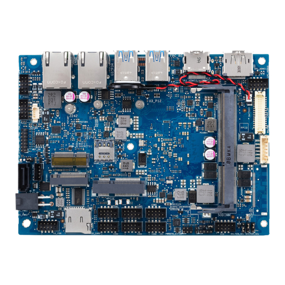
Page 15: Motherboard Layout
Motherboard layout Single Board Computer... - Page 16 Layout contents Page M.2 Wi-Fi slot Nano SIM Card slot Mini PCIe slot DIMM slot Low Pin Count connector Battery connector LVDS connector (on selected models) Back Light Inverter Power connector EDP Signal connector (on selected models) LVDS Panel Power Selection jumper (on selected models) Back Light Power Selection jumper Back Light Power Enable jumper GPIO connector...
-
Page 17: System Memory
System memory The motherboard comes with a Small Outline Dual Inline Memory Module (SODIMM) slot designed for DDR3L memory modules. Single Board Computer... -
Page 18: Onboard Jumpers
Onboard jumpers Clear RTC RAM jumper The Clear RTC RAM jumper allows you to clear the Real Time Clock (RTC) RAM in the CMOS, which contains the date, time, system passwords, and system setup parameters. To erase the RTC RAM: Turn OFF the computer and unplug the power cord. -
Page 19: Lvds Panel Power Selection Jumper (On Selected Models)
LVDS Panel Power Selection jumper (on selected models) The LVDS Panel Power jumper allows you to select the voltage for the LVDS panel. Back Light Power Selection jumper The Back Light Power Selection jumper allow you to select the voltage for the LVDS back light module. -
Page 20: Back Light Power Enable Jumper
Back Light Power Enable jumper The Back Light Power Enable jumper allows you to configure the power setting for the panel. HW WDT Enable jumper A watchdog timer is an electronic timer that is used to detect and recover from computer malfunctions. The HW WDT (watchdog timer) Enable jumper allows the HW watchdog resets the system automatically even when the system crashes. -
Page 21: Internal Connectors
Internal connectors SATA 6Gb/s & SATA Power connector The SATA 6Gb/s and SATA Power connectors allow you to connect SATA devices such as optical disc drives and hard disk drives via a SATA cable and power cable. Connector type Wafer HD 4P, 2.0mm pitch NOTE: Ensure to use the bundled cable when connecting a storage device to this connector. -
Page 22: Mini Pcie Slot
Mini PCIe slot The Mini PCIe slot allows you to install a Mini PCIe peripheral device. NOTE: The Mini PCIe peripheral device is purchased separately. Micro SD Card slot The Micro SD Card slot allows you to install a Micro SD card. NOTE: The Micro SD card is purchased separately. -
Page 23: Wi-Fi Slot
Nano SIM Card slot The Nano SIM Card slot allows you to install a Nano SIM card. NOTE: The Nano SIM card is purchased separately. M.2 Wi-Fi slot The M.2 Wi-Fi slot allows you to install an M.2 Wi-Fi module (E-key, type 2230). -
Page 24: Power Button Connector
M.2 slot The M.2 slot allows you to install 2242 M.2 devices such as 2242 M.2 SSD modules. NOTE: The M.2 SSD module is purchased separately. Power button connector The Power Button connector allows you to connect an external power button. -
Page 25: Lvds Connector (On Selected Models)
LVDS connector (on selected models) The LVDS connector allows you to connect a LCD monitor that supports a Low-voltage Differential Signaling (LVDS) interface. Connector type WAFER HD 2X15P 1.25MM pitch Back Light Inverter Power connector The Back Light Inverter Power connector is for the panel back light module power input. -
Page 26: Low Pin Count Connector
10. Low Pin Count connector The Low Pin Count connector allows you to connect a low pin count (LPC) debug card that offers a faster, more efficient motherboard troubleshooting solution. When connected to a debug card, users can view error and debugging codes on the card and get a better idea of initialization and recovery processes. -
Page 27: Edp Signal Connector (On Selected Models)
12. EDP Signal connector (on selected models) The EDP Signal connector allows you to connect an internal embedded DisplayPort. WtoB CON 40P 0.5MM,R/A Connector type ACES/88341-4001 Single Board Computer... -
Page 28: Gpio Connector
13. System Management Bus connector The System Management Bus (SMBus) connector allows you to connect SMBus devices. This connector is generally used for communication with the system and power management-related tasks. Connector type Header 1x4p, 2.0mm pitch 14. GPIO connector The GPIO connector allows you to connect a general purpose input/ output module which allows you to customize the digital signal input/ output. -
Page 29: I2C Connector
15. I2C connector The I2C (Inter-Integrated Circuit)connector allows you to connect an I2C compatible IoT security module. Connector type Header 2x3p, K6, 2.0mm pitch 16. SPI TPM connector The SPI TPM connector supports a Trusted Platform Module (TPM) system, which can securely store keys, digital certificates, passwords, and data. -
Page 30: Serial Port Connector
17. Serial Port connector The Serial (COM) Port connector allows you to connect a serial port module. Connect the serial port module cable to this connector, then install the module to a slot opening on the system chassis. Connector type BOX header 2x5p, K10, 2.0mm pitch NOTE: •... -
Page 31: Usb 2.0 Connector
18. USB 2.0 connector The USB 2.0 connector allows you to connect a USB module for additional USB 2.0 ports. The USB 2.0 connector provides data transfer speeds of up to 480 MB/s connection speed. Connector type BOX header 2x5p, K9, 2.0mm pitch WARNING! DO NOT connect a 1394 cable to the USB connectors. -
Page 32: Chassis Intrusion Connector
19. Chassis Intrusion connector The Chassis Intrusion connector allows you to connect a intrusion sensor or microswitch for the chassis intrusion detection feature. When you remove any chassis component, the sensor or microswitch triggers and sends a high level signal and records a chassis intrusion event. NOTE: By default, a jumper cap that disables the intrusion detection feature is installed on the connector to prevent accidental triggers. -
Page 33: Dc-In 4-Pin Power Connector
20. Fan connector The Fan connector allows you to connect a fan to cool the system. Connector type WtoB CON 4P,1.25mm,S/T WARNING! • D O NOT forget to connect the fan cable to the fan connector. Insufficient air flow inside the system may damage the motherboard components. These are not jumpers! Do not place jumper caps on the fan connectors! •... -
Page 34: System Panel Connector
21. System Panel connector The System Panel connector supports several chassis-mounted functions. Connector type BOX header 2x5p 2.0mm pitch • System Power LED connector (PLED) The 2-pin connector allow you to connect the System Power LED. The System Power LED lights up when the system is connected to a power source, or when you turn on the system power, and blinks when the system is in sleep mode. -
Page 35: Line Out / Mic Connector
22. Line Out / Mic connector The Line Out / Mic connector is for a line out / microphone module that supports HD Audio. Connect one end of the line Out / mic module cable to this connector. Connector type BOX header 2x5p, K8, 2.0mm pitch NOTE: We recommend that you connect a high-definition line out / mic module to this connector to avail of the motherboard’s high-... -
Page 36: Dc-In 4-Pin Power Connector
23. DC-in 4-Pin Power connector The DC-in 4-pin Power connector is for DC power input. Using a compatible power cable and power board, you may connect a suitable power supply with DC-in jacks. Connector type POWER CON 4P R/A Single Board Computer... -
Page 37: I/O Connectors
I/O connectors Front panel Front panel connectors DisplayPort HDMI port USB 3.2 Gen 1 ports LAN (RJ-45) ports Single Board Computer... - Page 38 Single Board Computer...
-
Page 39: Chapter 3: Upgrading Your Single Board Computer
Upgrading your Single Board Computer... -
Page 40: Installing Memory Modules
IMPORTANT! • E nsure that your hands are dry before proceeding with the rest of the installation process. Before installing any of the features in this guide, use a grounded wrist strap or touch a safely grounded object or metal object to avoid damaging them due to static electricity. • T urn off the power of your Single Board Computer, and allow it to cool for at least 10 minutes before performing any installation/ uninstallation process. -
Page 41: Installing 2.5" Storage Device
Installing 2.5” storage device Connect the storage device cable to the storage device. Connect the storage device cable to the SATA6G and SATA_PWR connectors on the motherboard. Single Board Computer... -
Page 42: Installing The Mini Pcie Card
Installing the Mini PCIe card Your motherboard comes with a Mini PCIe slot that allow you to install a Mini PCIe peripheral card. Align and insert the Mini PCIe card into the slot (A) and press it down and secure it in place using two (2) screws (B). Single Board Computer... -
Page 43: Installing A Nano Sim Card
Installing a Nano SIM card (optional) Remove the Mini PCIe card if there is a Mini PCIe card installed by removing the two (2) screws securing the Mini PCIe card first, then removing the Mini PCIe card. Push the Nano SIM cover towards the front I/O of your motherboard. Lift the Nano SIM cover. -
Page 44: Installing An Micro Sd Card
Installing an Micro SD card Insert your Micro SD card into the Micro SD card slot. Ensure that the Micro SD card is pushed all the way into the Micro SD card slot. Single Board Computer... -
Page 45: Installing The Wireless Card
Installing the wireless card Remove the M.2 stand screw. Align and insert the wireless card into its slot on the motherboard, then gently push down the wireless card on top of the screw hole and fasten it using the previously removed stand screw. (optional) Connect the antennas to your wireless card. -
Page 46: Installing An M.2 Ssd
Installing an M.2 SSD (optional) Replace the stand screw if it has been removed. Align and insert the M.2 SSD into its slot inside the Single Board Computer, then gently push down the M.2 SSD on top of the stand screw hole and fasten it using a screw. -
Page 47: Chapter 4: Bios Setup
BIOS Setup... -
Page 48: Getting To Know Your Bios
Getting to know your BIOS The BIOS (Basic Input and Output System) stores system hardware settings such as Storage Device Configuration, Advanced Power Management, and Boot Device Configuration that are needed for system startup. Under normal circumstances, the default BIOS settings apply to most conditions to ensure optimal performance. -
Page 49: Bios Setup Program
BIOS setup program Use the BIOS Setup program to update the BIOS or configure its parameters. The BIOS screens include navigation keys and brief online help to guide you in using the BIOS Setup program. Entering BIOS Setup at startup To enter BIOS Setup at startup: •... - Page 50 BIOS menu screen This section provides a brief introduction of the BIOS Interface of your Single Board Computer. Menu items Menu bar Configuration fields General help Navigation keys Menu bar The menu bar on top of the screen has the following main items: Main For changing the basic system configuration Advanced...
-
Page 51: Main Menu
Main Menu When you enter the BIOS Setup program, the Main menu screen appears. The Main menu provides you an overview of the basic system information, and allows you to set the system date and time. Scroll down to display the other BIOS items. -
Page 52: Advanced Menu
Incorrect field values can cause the system to malfunction. Start ASUS EzFlash Allows you to run ASUS EzFlash BIOS ROM Utility when you press <Enter>. Refer to the ASUS EzFlash Utility section for details. WARNING! Ensure to back up your Bitlocker recovery key and suspend Bitlocker encryption in the operating system before updating your BIOS. -
Page 53: Trusted Computing
OS Type Allows you to select your installed operating system. Execute the Microsoft® Secure Boot check. Only select this option when booting on Windows® UEFI mode or other Microsoft® Secure Boot compliant OS. [Other OS] Get the optimized function when booting on Windows®... - Page 54 SHA-1 PCR Bank Allows you to enable or disable SHA-1 PCR Bank. Configuration options: [Disable] [Enable] SHA256 PCR Bank Allows you to enable or disable SHA256 PCR Bank. Configuration options: [Disable] [Enable] Pending operation Allows you to schedule an operation for the Security Device. Configuration options: [None] [TPM Clear] NOTE: Your computer will reboot during restart in order to change the state of Security Device.
-
Page 55: Pch Storage Configuration
Physical Presence Spec Version Select to tell the OS to support PPI Spec Version 1.2 or 1.3. Configuration options: [1.2] [1.3] NOTE: Some HCK tests might not support version 1.3. 4.4.2 PCH Storage Configuration While entering Setup, the BIOS automatically detects the presence of SATA devices. - Page 56 NOTE: The following items appear only when SATA Port Enable is set to [Enabled]. Aggressive LPM Support This item is designed for LPM (link power management) support with a better energy saving conditions. Configuration options: [Disabled] [Enabled] SATA6G SATA6G Port Allows you to enable or disable the SATA port.
-
Page 57: Onboard Devices Configuration
4.4.3 Onboard Devices Configuration HD Audio Support Allows you to enable or disable HD-Audio support. Configuration options: [Disabled] [Enabled] Intel LAN Allows you to enable or disable Intel LAN. Configuration options: [Disabled] [Enabled] NOTE: The following item appears only when Intel LAN is set to [Enabled]. - Page 58 M.2 WiFi(E-Key) PCIE Port Allows you to enable or disable Wi-Fi Controller. Configuration options: [Disabled] [Enabled] USB Port Allows you to enable or disable Bluetooth Controller. Configuration options: [Disabled] [Enabled] Mini PCIe PCIE Port Allows you to enable or disable PCIe Controller. Configuration options: [Disabled] [Enabled] USB Port Allows you to enable or disable USB Controller.
-
Page 59: Acpi Settings
4.4.4 ACPI Settings The items in this menu allow you to configure the system ACPI parameters. Enable ACPI Auto Configuration Allows you to enable or disable the BIOS ACPI Auto Configuration. Configuration options: [Disabled] [Enabled] NOTE: The following item appears only when Enable ACPI Auto Configuration is set to [Disabled]. -
Page 60: Apm Configuration
4.4.5 APM Configuration Allows you to configure the Advance Power Management (APM) settings. ErP Ready Allows you to switch off some power at S4+S5 or S5 to get the system ready for ErP requirement. When set to [Enabled], all other PME options will be switched off. Configuration options: [Disabled] [Enabled(S4+S5] [Enabled(S5)] Restore AC Power Loss [S0] The system goes into ON state after an AC power loss. -
Page 61: Smart Settings
4.4.6 SMART Settings The items in this menu allow you to configure the SMART Self Test settings. SMART Self Test Allows you to run SMART Self Test on all HDDs during POST. Configuration options: [Disabled] [Enabled] 4.4.7 NCT6116D Super IO Configuration Serial Port 1-2 Configuration Allows you to set the parameters of Serial Port 1-2. - Page 62 NOTE: The following items appear only when Serial Port is set to [Enabled]. Mode Select Configuration options: [RS232] [RS485] [RS422] Change Settings Allows you to choose the setting for Super IO device. Configuration options: [Auto] [IO=3F8h; IRQ=4;] [IO=3F8h; IRQ=3, 4, 5, 6, 7, 9, 10, 11, 12;] [IO=2F8h;...
-
Page 63: Nct6116D Hw Monitor
4.4.8 NCT6116D HW Monitor 4.4.9 Serial Port Console Redirection COM1-6 Console Redirection Allows you to enable or disable the console redirection feature. Configuration options: [Disabled] [Enabled] Single Board Computer... - Page 64 NOTE: The following item appears only when Console Redirection is set to [Enabled]. Console Redirection Settings This item becomes configurable only when you enable the Console Redirection item. The settings specify how the host computer and the remote computer (which the user is using) will exchange data. Both computers should have the same or compatible settings.
- Page 65 Stop Bits Stop bits indicate the end of a serial data packet. (A start bit indicates the beginning.) The standard setting is 1 stop bit. Communication with slow devices may require more than 1 stop bit. Configuration options: [1] [2] Flow Control Flow control can prevent data loss from buffer overflow. When sending data, if the receiving buffers are full, a “stop” signal can be sent to stop...
- Page 66 Resolution This allows you to set the number of rows and columns supported on the Legacy OS. Configuration options: [80x24] [80x25] Redirection After POST This setting allows you to specify if Bootloader is selected than Legacy console redirection. [Always Enable] Legacy Console Redirection is enabled for Legacy OS.
-
Page 67: Cpu Configuration
Flow Control Allows you to set the flow control to prevent data loss from buffer overflow. Configuration options: [None] [Hardware RTS/CTS] [Software Xon/Xoff] 4.4.10 CPU Configuration The items in this menu show the CPU-related information that the BIOS automatically detects. Socket 0 CPU Information Allows you to view Socket specific CPU information. CPU Power Management EIST Allows you to enable or disable Intel SpeedStep. Configuration: [Disabled] [Enabled] NOTE: The following item appears only when EIST is set to [Enabled]. - Page 68 Boot performance mode Allows you to select the performance state that the BIOS will set before OS handoff. Configuration options: [Max Performance] [Max Battery] C-States Allows you to enable or disable C-States. Configuration options: [Disabled] [Enabled] NOTE: The following items appear only when C-States is set to [Enabled].
- Page 69 NOTE: The following items appear only when Power Limit 1 Enable is set to [Enabled]. Power Limit 1 Power Limit 1 Clamp Mode Allows you to enable or disable Power Limit 1 Clamp Mode. Configuration options: [Disabled] [Enabled] Power Limit 1 Power Allows you to set the Power Limit 1 in Watts.
- Page 70 Intel Virtualization Technology When set to [Enabled], a VMM can utilize the additional hardware capabilities provided by Vanderpool Technology. Configuration options: [Disabled] [Enabled] VT-d Allows you to enable or disable CPU VT-d. Configuration options: [Disabled] [Enabled] Bi-directional PROCHOT When a processor thermal sensor trips (either core), the PROCHOT# will be driven.
-
Page 71: Ami Graphic Output Protocol Policy
4.4.11 AMI Graphic Output Protocol Policy NOTE: This option only appears if OS type in Advanced menu is set to [Windows UEFI Mode]. Output Select Allows you to select the output interface. Configuration options: [DVI2] [HDMI2] 4.4.12 PCI Subsystem Settings Allows you to configure PCI, PCI-X, and PCI Express Settings. -
Page 72: Usb Configuration
Hot-Plug Support Globally enables or disables Hot-Plug support for the entire system. If system has Hot-Plug capable Slots and this option set to [Enabled], it provides a Setup screen for selecting PCI resource padding for Hot-Plug. Configuration options: [Disabled] [Enabled] 4.4.13 USB Configuration NOTE: The USB Devices item shows the auto-detected values. - Page 73 XHCI Hand-off NOTE: This item is set to [Disabled] by default for the EHCI (enhanced host controller interface) support by XHCI drivers in operating systems. [Disabled] Support XHCI by XHCI drivers for operating systems with XHCI support. [Enabled] Support XHCI by BIOS for operating systems without XHCI support.
-
Page 74: Network Stack Configuration
4.4.14 Network Stack Configuration Allows you to configure the network stack configuration. Network Stack Allows you to enable or disable UEFI Network Stack. Configuration options: [Disabled] [Enabled] NOTE: The following items appear only when Network Stack is set to [Enabled]. Ipv4 PXE Support Enables or disables the Ipv4 PXE Boot Support. -
Page 75: Sdio Configuration
4.4.15 SDIO Configuration SDIO Access Mode [Auto] Access SD device in DMA mode if controller supports it, otherwise access SD device in PIO mode. [ADMA] Access SD device in ADMA mode. [SDMA] Access SD device in SDMA mode. [PIO] Access SD device in PIO mode. 4.4.16 Platform Trust Technology TPM Device Selection Allows you to select the TPM device. -
Page 76: Security Configuration
4.4.17 Security Configuration TXE HMRFPO Allows you to enable or disable TXE HMRFPO. Configuration options: [Disabled] [Enabled] TXE EOP Message Allows you to enable or disable sending EOP Message before entering OS. Configuration options: [Disabled] [Enabled] 4.4.18 LFP Configuration IGD Flat Panel Allows you to enable or disable IGD video output to onboard LVDS. -
Page 77: Thermal
EDID Data Source Allows you to select the EDID data source. Configuration options: [Pre-defined] [Flat Panel Display] 4.4.19 Thermal Automatic Thermal Reporting Allows you to configure _CRT, _PSV, and _ACO automatically based on values recommended in BWG’s Thermal Reporting for Thermal Management settings. - Page 78 Active Trip Point This value controls the temperature of the ACPI Active Trip Point - the point in which the OS will turn the fan on. Configuration options: [15 C] [23 C] [31 C] [39 C] [47 C] [55 C] [60 C] [63 C] [71 C] [79 C] [87 C] [95 C] [103 C] [110 C] Single Board Computer...
-
Page 79: Security
Security This menu allows a new password to be created or a current password to be changed. The menu also enables or disables the Secure Boot state and lets the user configure the System Mode state. Administrator Password To set an administrator password: Select the Administrator Password item and press <Enter>. - Page 80 NOTE: To clear the administrator password, follow the same steps as in changing an administrator password, but press <Enter> when prompted to create/confirm the password. User Password To set a user password: Select the User Password item and press <Enter>. From the Create New Password box, key in a password, then press <Enter>.
- Page 81 Secure Boot Secure Boot can be enabled if the system is running in User mode with enrolled platform Key (EPK) or if the CSM function is disabled. Configuration options: [Disabled] [Enabled] Key Management The Key Management item allows you to modify Secure Boot variables and set Key Management page.
-
Page 82: Boot Menu
Boot menu The Boot menu items allow you to change the system boot options. Fast Boot [Disabled] Allows your system to go back to its normal boot speed. [Enabled] Allows your system to accelerate the boot speed. NOTE: The following items appear only when Fast Boot is set to [Enabled]. - Page 83 VGA Support [Auto] Only install the Legacy OpRom with Legacy OS and logo will not be shown during POST. [EFI Driver] EFI driver will still be installed with the EFI OS. USB Support [Disabled] All USB devices will NOT be available until after OS boot. [Full Initial] All USB devices will be available in OS and POST.
- Page 84 Network / Storage / Video This option allows you to control the execution of UEFI and Legacy PXE/ Storage/ Video OpROM. Configuration options: [Do not launch] [UEFI] [Legacy] Other PCI devices This item determines the OpROM execution policy for devices other than Network, Storage, or Video.
- Page 85 T o access Windows® OS in Safe Mode, press <F8> after POST (Windows® 8 not supported). • T o select the boot device during system startup, press <F8> when the ASUS Logo appears. Boot Override These items displays the available devices. The number of device items that appears on the screen depends on the number of devices installed in the system.
-
Page 86: Save & Exit Menu
Save & Exit menu The Save & Exit menu items allow you to save or discard your changes to the BIOS items. NOTE: Pressing <Esc> does not immediately exit this menu. Select one of the options from this menu or <F10> from the legend bar to exit. Discard Changes and Exit Exit System setup without saving any changes. -
Page 87: Updating Your Bios
Copy the original motherboard BIOS using the BUPDATER utility. 4.8.1 ASUS CrashFree BIOS 3 utility The ASUS CrashFree BIOS 3 is an auto recovery tool that allows you to restore the BIOS file when it fails or gets corrupted during the updating process. You can update a corrupted BIOS file using a USB flash drive that contains the updated BIOS file. -
Page 88: Asus Ezflash Utility
Visit the ASUS website at www.asus.com to download the latest BIOS file. 4.8.2 ASUS EzFlash Utility The ASUS EzFlash Utility feature allows you to update the BIOS using a USB flash disk without having to use a DOS-based utility. IMPORTANT! Download the latest BIOS from the ASUS website at www.asus.com before using this utility. - Page 89 Enter the BIOS setup program. Go to the Advanced menu to select Start ASUS EzFlash and press <Enter> to enable it. WARNING! Ensure to back up your Bitlocker recovery key and suspend Bitlocker encryption in the operating system before updating your BIOS.
-
Page 90: Bupdater Utility
The BUPDATER utility allows you to update the BIOS file in DOS environment using a bootable USB flash disk drive with the updated BIOS file. Updating the BIOS file To update the BIOS file using the BUPDATER utility: Visit the ASUS website at www.asus.com and download the latest BIOS file for the motherboard. Save the BIOS file to a bootable USB flash disk drive. Download the BUPDATER utility (BUPDATER.exe) from the ASUS support website at support.asus.com to the bootable USB flash disk... - Page 91 The utility verifies the file, then starts updating the BIOS file. ASUSTek. EzFlash Utility Current Platform New Platform Platform : E395S-IM-AA Platform : E395S-IM-AA Version : 0204 Version : 0401 Build date: 05/15/2019 Build date: 06/19/2019 Start Programming Flash. DO NOT SHUTDOWN THE SYSTEM!!! Write WARNING! DO NOT shut down or reset the system while updating the BIOS to prevent system boot failure!
- Page 92 Single Board Computer...
-
Page 93: Appendix
Appendix... -
Page 94: Safety Information
Safety information Your Single Board Computer is designed and tested to meet the latest standards of safety for information technology equipment. However, to ensure your safety, it is important that you read the following safety instructions. Setting up your system •... -
Page 95: Care During Use
Care during use • Do not walk on the power cord or allow anything to rest on it. • Do not spill water or any other liquids on your system. • When the system is turned off, a small amount of electrical current still flows. Always unplug the power cord from the power outlets before cleaning the system. • If you encounter the following technical problems with the product, unplug the power cord and contact a qualified service technician or your retailer. – The power cord or plug is damaged. – Liquid has been spilled into the system. –... -
Page 96: Regulatory Notices
ASUS REACH website at http://csr.asus.com/ english/REACH.htm ASUS Recycling/Takeback Services ASUS recycling and takeback programs come from our commitment to the highest standards for protecting our environment. We believe in providing solutions for you to be able to responsibly recycle our products, batteries, other components, as well as the packaging materials. - Page 97 Federal Communications Commission Statement This device complies with Part 15 of the FCC Rules. Operation is subject to the following two conditions: • This device may not cause harmful interference, and • This device must accept any interference received including interference that may cause undesired operation. This equipment has been tested and found to comply with the limits for a Class A digital device, pursuant to part 15 of the FCC Rules.
- Page 98 ISED Radiation Exposure Statement for Canada This equipment complies with ISED radiation exposure limits set forth for an uncontrolled environment. To maintain compliance with ISED RF exposure compliance requirements, please avoid direct contact to the transmitting antenna during transmitting. End users must follow the specific operating instructions for satisfying RF exposure compliance.
- Page 99 Europe ETSI 2.412-2.472 GHz Ch01 through Ch13 Regional notice for Singapore Complies with This ASUS product complies with IMDA Standards. IMDA Standards DB103778 Regional notice for California WARNING! This product contains chemicals known to the State of California to cause cancer, and birth defects or other reproductive harm.
- Page 100 Agency and the U.S. Department of Energy helping us all save money and protect the environment through energy efficient products and practices. All ASUS products with the ENERGY STAR logo comply with the ENERGY STAR standard, and the power management feature is enabled by default.
-
Page 101: Asus Contact Information
+1-510-608-4555 Web site http://www.asus.com/us/ Technical Support Support fax +1-812-284-0883 Telephone +1-812-282-2787 Online support https://www.asus.com/support/Product/ContactUs/Services/ questionform/?lang=en-us ASUS COMPUTER GmbH (Germany and Austria) Address Harkort Str. 21-23, 40880 Ratingen, Germany +49-2102-959931 Web site http://www.asus.com/de Online contact http://eu-rma.asus.com/sales Technical Support Telephone +49-2102-5789555 Support Fax... - Page 102 Manufacturer ASUSTeK Computer Inc. Tel: +886-2-2894-3447 Address: 4F, No. 150, LI-TE RD., PEITOU, TAIPEI 112, TAIWAN Authorised ASUSTeK Computer GmbH representative in Address: HARKORT STR. 21-23, 40880 RATINGEN, Europe GERMANY Single Board Computer...
Need help?
Do you have a question about the E394S-IM-AA and is the answer not in the manual?
Questions and answers