
Related Manuals for Maxtec R217P65


Summary of Contents for Maxtec R217P65
- Page 1 Nitrogen Analyzer O P E R A T I N G M A N U A L & I N S T R U C T I O N S F O R U S E R 2 1 7 P 6 5 , R 2 1 7 P 6 6 , R 2 1 7 P 6 7 R217M65 Rev.
-
Page 3: Classification
Product Disposal Instructions: The sensor, batteries, and circuit board are not suitable for regular trash disposal. Return sensor to Maxtec for proper disposal or dispose according to local guidelines. Follow local guidelines for disposal of other components. WARRANTY The MaxN + analyzer is designed for nitrogen delivery equipment and systems. -
Page 4: Warnings
This product will perform only as designed if installed and operated in accordance with the manufacturer’s operating instructions. » Use only genuine Maxtec accessories and replacement parts. Failure to do so may seriously impair the analyzer’s performance. Repair of this equipment must be performed by a qualified service technician experienced in repair of portable hand held equipment. -
Page 5: Table Of Contents
9.2.3 Carrying Options........10 866.4.Maxtec... -
Page 7: System Overview
Follow instructions for use. Calibration Button Warning Low Battery Meets ETL standards Do not throw away. Follow local Percent guidelines for disposal. Manufacturer Calibration required REF Catalog Number Do Not IPX1 Serial Number Drip Proof Lot code/Batch code 866.4.Maxtec www.maxtec.com... -
Page 8: Component Identification
- This key is used to calibrate the device. Holding the key for more than three seconds will force the device to enter a calibration mode. Sample Inlet Connection - This is the port at which the device is connected to determine oxygen concentration. 866.4.Maxtec www.maxtec.com... -
Page 9: Max-250 Oxygen Sensor
(2 liters per minute is recommended). 3. Using the “ON/OFF” key, make sure the unit FIGURE 2 is in the power “ON” mode. FIGURE 2 4. Allow the nitrogen reading to stabilize. This will normally take about 30 seconds or more. 866.4.Maxtec www.maxtec.com... -
Page 10: Calibrating The Maxn + Analyzer
The MaxN + analyzer should be calibrated upon initial power-up. Thereafter, Maxtec recommends calibration on a weekly basis. To serve as a reminder, a one week timer is started with each new calibration. At the end of one week a reminder icon “ ” will appear on the bottom of the LCD. Calibration is recommended if the user is unsure when the last calibration procedure was performed, or if the measurement value is in question. -
Page 11: Temperature Effects
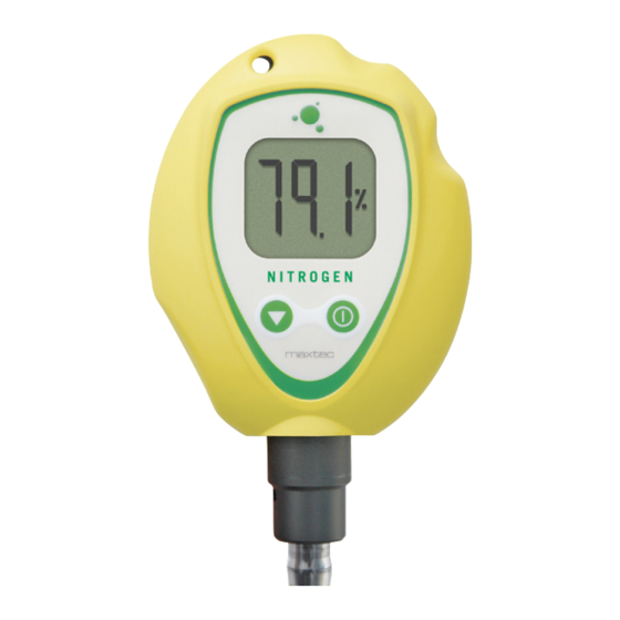
E02: No sensor attached Open the hand held MaxN + analyzer and disconnect and reconnect sensor. Unit should perform an auto calibration and should read 79.1%. If not, contact Customer Service for possible sensor replacement. 866.4.Maxtec www.maxtec.com... -
Page 12: Changing The Batteries
Press and hold the Calibration Button for three seconds to manually force a new calibration. If unit repeats this error more than three times, contact Maxtec Customer Service for possible sensor replacement. CAL Err hi: Sensor voltage too high Press and hold the Calibration Button for three seconds to manually force a new calibration. -
Page 13: Changing The Oxygen Sensor
Reinsert the three screws and tighten until the screws are snug. Verify the unit operates properly. The device will automatically perform a calibration and begin displaying % of oxygen. 866.4.Maxtec www.maxtec.com... -
Page 14: Maxn + Ae (R217P66)
» Clean the sensor with a cloth moistened with a 65% alcohol/water solution. » Maxtec does not recommend use of spray disenfectants because they can contain salt, which can accumulate in the sensor membrane and impair readings. -
Page 15: Specifications
+ SPARE PARTS AND ACCESSORIES 9.1 Standard Replacement Parts and Accessories Part Number Item R125P02-011 MAX-250+ Sensor R125P03-002 MAX-250E Sensor R217P08 Gasket RP06P25 #4-40 Pan Head Stainless Steel Screw R217P16-001 Front Assembly (Includes Board & LCD) R217P11-002 Back Assembly R217P09-001 Overlay 866.4.Maxtec www.maxtec.com... -
Page 16: Optional Accessories
NOTE: Repair of this equipment must be preformed by a qualified service technician experienced in repair of portable hand held medical equipment. Equipment in need of repair shall be sent to: Maxtec Customer Service Department 2305 South 1070 West Salt Lake City, Ut 84119 (Include RMA number issued by Customer Service) 866.4.Maxtec...
Need help?
Do you have a question about the R217P65 and is the answer not in the manual?
Questions and answers