
Related Manuals for Clarke Air CAT176


Summary of Contents for Clarke Air CAT176
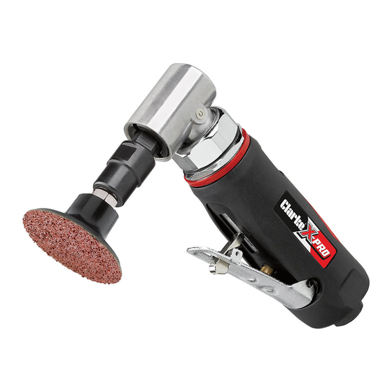
- Page 1 MULTI-SANDER KIT MODEL NO: CAT176 PART NO: 3120193 OPERATING & MAINTENANCE INSTRUCTIONS ORIGINAL INSTRUCTIONS GC0418 - ISS 1...
-
Page 2: Safety Symbols
Your tool kit has been designed to give long and trouble free service. If, however, having followed the instructions in this booklet carefully, you encounter problems, take the unit to your local CLARKE dealer. SAFETY SYMBOLS The following safety symbols are to be found on the air tool. -
Page 3: General Safety Rules
GENERAL SAFETY RULES CAUTION: FAILURE TO FOLLOW THESE PRECAUTIONS COULD RESULT IN PERSONAL INJURY, AND/OR DAMAGE TO PROPERTY. WORK ENVIRONMENT 1. Keep the work area clean and tidy. 2. Dress appropriately - Do not wear loose clothing or jewellery. Tie long hair out of the way. - Page 4 7. Do not fit the tool to any stand or clamping device that may damage it. 8. Do not carry out any alterations or modifications to the tool. 9. Always disconnect from the air supply when: • Performing any maintenance. •...
-
Page 5: Transportation And Storage
<2.9 m/s Please note that the details and specifications contained here are correct at the time of going to print. However CLARKE International reserve the right to change specifications at any time without prior notice. Parts & Service: 020 8988 7400 / E-mail: Parts@clarkeinternational.com or Service@clarkeinternational.com... -
Page 6: Contents Of The Kit
5 x 50 mm Sanding Pads When opening the case for the first time, check that all items are present. Any damage or deficiency should be reported to your CLARKE dealer immediately. Parts & Service: 020 8988 7400 / E-mail: Parts@clarkeinternational.com or Service@clarkeinternational.com... -
Page 7: Compressed Air Requirements
COMPRESSED AIR REQUIREMENTS WARNING: COMPRESSED AIR CAN BE DANGEROUS. ENSURE THAT YOU ARE FAMILIAR WITH ALL PRECAUTIONS RELATING TO THE USE OF AIR COMPRESSORS AND COMPRESSED AIR SUPPLIES. • Use only clean, dry, regulated compressed air as a power source. •... -
Page 8: Before Use
Your air tool is now ready for use. You can fit a whip hose with a quick fit coupling if required (available from your Clarke dealer). INSTALLING THE COLLET 1. Select the grinding stone you require. 2. Two collets of different sizes are provided. -
Page 9: Fitting The Sanding Disc
FITTING THE GRINDING STONE IMPORTANT: Never use chipped or cracked grindstones. 1. Slip the shank of the chosen stone into the collet and tighten the retaining collar finger tight. 2. Place the smaller of the two wrenches over the collet seat to stop the tool from rotating. -
Page 10: Troubleshooting
2. Motor parts worn. 2. Return to Clarke dealer for repair. 3. Worn or sticking 3. Drip air tool lubricating mechanism due to oil into the air inlet. Allow lack of lubricant. -
Page 11: Disconnecting The Air Supply
1. Before use, drain water from the air tank, air line and compressor. 2. Pour a few drops of CLARKE airline oil into the air inlet. This should be carried out regardless of whether or not an in-line mini oiler is used. If an in-line lubricator is not used, this procedure should be repeated after every two to three hours of use. -
Page 12: Service And Repair
If the tool is to be stored, or is idle for longer than 24 hours, run a few drops of Clarke air line oil into the air inlet, and run the tool for 5 seconds in order to lubricate the internal parts. -
Page 13: Declaration Of Conformity
DECLARATION OF CONFORMITY Parts & Service: 020 8988 7400 / E-mail: Parts@clarkeinternational.com or Service@clarkeinternational.com... -
Page 14: Parts List
PARTS LIST Description No Description Main Housing Bush Lever Trigger Front Plate Lever Block Steel Ball Spring Bearing Roll Pin Primary Gear Roll Pin Decorating Ring O-Ring End Fixing Ring O-Ring End Nut Valve Stem Gear Casing Spring Lubricating Nipple O-Ring Bearing Screw Cap... -
Page 15: Parts Diagram
PARTS DIAGRAM Parts & Service: 020 8988 7400 / E-mail: Parts@clarkeinternational.com or Service@clarkeinternational.com...
Need help?
Do you have a question about the Air CAT176 and is the answer not in the manual?
Questions and answers