Sign In
Upload
Manuals
Brands
Inovance Manuals
Controller
MD500 Series
Inovance MD500 Series AC Drive Manuals
Manuals and User Guides for Inovance MD500 Series AC Drive. We have
4
Inovance MD500 Series AC Drive manuals available for free PDF download: User Manual
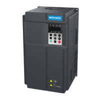
Inovance MD500 Series User Manual (341 pages)
High Performance
Brand:
Inovance
| Category:
Controller
| Size: 28 MB
Table of Contents
Please Read this Important Information
2
Table of Contents
3
Safety Information and Precautions
5
Electrical Installation - Safety
6
Working Environment and Handling
6
AC Motor (Induction/Asynchronous)
7
Adjusting AC Drive Parameters
7
Product Information
8
Product Type Identification
9
Chapter 1 Product Information
9
Internal View of MD500
10
Ratings
12
Technical Specifications
13
Mechanical Installation
18
Installation Environment
19
Chapter 2 Mechanical Installation
19
Mounting Orientation and Clearance
20
Installation of an Air Guide Plate
21
Mounting Dimensions
22
Installation Method and Procedures
23
Backplate Mounting
23
Backplate-Mounted Installation of a Plastic Housing
24
Backplate-Mounted Installation of a Sheet Metal Housing
24
Through Hole Mounting
25
Preparing the Backplate for Hole Cut-Out
26
Installing the AC Drive into the Hole Cut-Out
26
Remove and Refit the Front Cover
28
Electrical Installation
30
Typical System Connection
31
Chapter 3 Electrical Installation
31
Main Circuit Wiring
32
Main Circuit Terminals
32
Cable Dimensions and Tightening Torque
33
Crimp Terminal Recommendation
37
Main Circuit Cable Recommendations
39
Main Circuit Cable Selection
39
Power Input
39
DC Bus Terminals
40
Braking Resistor
40
AC Drive Outputs U, V, W to Motor
40
Cable Support Bracket Models
41
Grounding (PE) Connection
42
Main Circuit Cable Protection
43
Power Input Protection
43
Power Grid System
43
Control Circuit Wiring
44
Terminal Arrangement
44
Terminal Function
45
Wiring Diagrams
47
Selection of Control Circuit Wirings
47
Cabling Requirements
47
Wiring of AI1
48
Wiring of AI2
48
Wiring of DI1 to DI5
49
Source Wiring
50
Wiring of DI5 (High-Speed Pulse Input)
50
Wiring of DO
51
Wiring of High-Speed Output FM
51
Wiring of Relay
52
Wire Size and Torque Specification
52
Wiring Checklist
53
Operating Panel
54
Keypad and Display
55
Inbuilt LED Operating Panel
55
Chapter 4 Operating Panel (Keypad & Display)
55
Introduction
55
Keys on LED Operating Panel
56
Relevant Parameters for Operating Panel Setting
57
Status Indicators
57
Unit Indicators
58
LED Display
58
LED Operating Panel Menu Structure
59
Unmodifiable Parameters
61
Overall Arrangement of Function Parameters
62
Selection of Function Parameter Group
62
Selection of Displaying a and U Groups
62
Function Parameter Operations
63
Viewing Function Parameters
63
Editing Function Parameters
64
MF.K Key Function
65
Saving and Restoring Settings
65
Password Security
66
Quick Setup
68
Operating Panel View
69
Chapter 5 Quick Setup
69
Get Familiar with Operating Panel
69
Setup Flowchart
70
Description of Parameters
82
Start/Stop Command Source
83
Chapter 6 Description of Parameters
83
Terminal I/O Control
84
Serial Communication
90
Set Frequency Reference
91
Select Main Frequency Reference Setting Channel
92
Select a Required Curve for AI Terminal
97
Pulse Reference (DI5)
99
Multi-Reference
100
Simple PLC
101
PID Reference
104
Serial Comms.
110
Setting Auxiliary Frequency Reference
112
Main & Auxiliary Calculation
114
Command Source + Frequency Reference Setting Channel
116
Frequency Reference Limit
117
Running Mode When Frequency Reference below Lower Limit
117
Start Mode
118
Start/Stop the AC Drive
118
Stop Mode
121
Acceleration/Deceleration Time and S-Curve Setting
123
Motor Auto-Tuning
125
Control Performance
129
V/F Curve
129
V/F Separation Curve
131
Current Limit Control
132
Torque Boost
132
Voltage Limit and Braking Unit Applied Voltage
134
Speed Loop
135
SVC/FVC Slip Compensation Gain
135
SVC Speed Feedback Stability
136
Setting Torque Limit in Torque Control
138
Auxiliary Control
139
Current Loop
139
Improving Field Weakening Area Performance
139
Motor Overload Protection
140
Protections
140
Phase Loss Protection
141
Fault Protection Action Selection
142
Fault Reset
142
Motor Overheat Protection
144
Power Dip Ride-Through
144
Load Lost Protection
145
Overspeed Protection
146
Speed Error Protection
146
Undervoltage & Overvoltage Threshold and Overcurrent Fast Prevention
146
Output Overcurrent Protection
147
Monitoring
148
View Parameters in Group U0
150
Process Control
155
The Wobble Function
155
Fixed Length Control
156
Counting
157
Motor 2 Parameters
159
User Programmable Card
160
Parameter Settings of Controlling MD500 by PLC Programming Function
162
Master and Slave Control
165
Droop Control
171
Control Circuit Terminals
173
Function of DI Terminals
173
Function of DO Terminals
177
Function of VDI Terminals
180
Function of VDO Terminals
181
Function of the AI Terminals
182
Function of the AO and Pulse Output Terminals
183
Communication
185
Read and Write Function Parameters
185
Read and Write State Parameters
187
Write RUN Command
189
Write Frequency/Torque Reference
191
Control of Analog and High-Speed Pulse Output (AO, FMR)
192
Control of Digital Output (DO, Relay, FMR)
192
Parameter Initialization
192
Auxiliary Function
193
Jog
193
FWD/REV Switchover Dead-Zone Time, Reverse Run Prohibited
194
Jump Frequency
194
Frequency Detection (FDT)
196
Frequency Reference Reached Detection Width
196
Acceleration/Deceleration Time Switchover
197
Frequency Reached Detection
198
Zero Current Detection
198
Current Detection
199
Timing Function
199
AI1 Input Voltage Upper/Lower Limit
200
Cooling Fan
200
Hibernating and Wakeup
200
Module Temperature
200
Deceleration Time for Emergency Stop
201
Output Power Correction
201
Running Time Threshold this Time
201
Interfaces and Communication
202
About Use of MD500 Terminals
203
Filter Time and Delay Functions
203
Use of DI Terminals
203
Use of DO Terminals
203
Chapter 7 Interfaces and Communication
203
Use of AI Terminals
204
Use of AO Terminals
204
Use of PG Terminal
205
Serial Communication
206
About Multi-Functional Extension Interfaces
207
Definition of Communication Data Address
208
Parameter Data
208
Non-Parameter Data
209
Bus Structure
211
Modbus Communication Protocol
211
Data Format
212
CRC Check
214
Definition of Communication Parameter Addresses
215
Stop/Run Parameters
216
Group Fd Communication Parameter Description
218
Peripherals and Options
220
Chapter 8 Peripherals and Options
221
Description of Peripheral Electrical Devices
223
MCCB, Fuse and Contactor
224
Braking Unit and Braking Resistor
225
Mounting Dimensions of MDBUN Series Braking Unit
227
Mounting Dimensions of Energy Feedback Unit
228
Mounting Dimensions of MDBU Series Braking Unit
228
External Operating Panel
229
Extension Cards
230
Functional Extension Cards
232
Extension Communication Cards
239
Extension PG Cards
249
Through-Hole Mounting Bracket
257
Emc
261
Chapter 9 Technical Data
261
Installing Fuse on the Input Side
262
Definition of Terms
263
Selection of Peripheral EMC Devices
263
Simple EMC Filter
268
Safety Capacitance Box and Ferrite Core
269
AC Input Reactor Installation
270
AC Output Reactor Installation
272
DV/Dt Reactor Installation
276
Common-Mode Filter
278
Breaker & Fuse Selection
279
Shielded Cable
279
Solutions to Current Leakage
280
Solutions to Common EMC Interference Problems
281
De-Rating
282
Maintenance and Inspection
284
Daily Inspection
285
Chapter 10 Maintenance and Inspection
285
Periodic Inspection Items
287
Insulation Test on Main Circuit
288
Replacement of Wearing Components
289
Removing and Installing the Fan of a Plastic Housing
290
Removing and Installing the Fan of a Sheet Metal Housing
291
Storage
292
Warranty Agreement
292
Troubleshooting
294
Chapter 11 Troubleshooting
295
Safety Information
295
Troubleshooting During Trial Run
296
Fault Display
298
Resetting Fault
298
Faults and Diagnostics
299
Symptoms and Diagnostics
306
Appendix A Parameter Table
309
Introduction
309
Standard Parameters
310
Monitoring Function Codes
332
Index
334
Advertisement
Inovance MD500 Series User Manual (322 pages)
Brand:
Inovance
| Category:
Inverter
| Size: 6 MB
Table of Contents
Preface
1
Introduction
2
Table of Contents
5
Safety Information and Precautions
10
Safety Information
11
General Precautions
14
Product Information
21
Components of the MD500
22
Mechanical Installation
26
Installation Environment
26
Mounting Orientation and Clearance
27
Physical Appearance and Mounting Dimensions
29
Installation Method and Proces
31
Removing and Installing the
36
Electrical Installation
40
Typical System Connection
40
Main Circuit Wiring
41
Control Circuit Wiring
50
Wiring Checklist
56
Operations
58
Introduction to the Operating Panel
58
Operating Panel Menu Structure
62
Overall Arrangement of Function Parameters
65
Function Parameter Operations
66
Quick Setup
70
Get Familiar with Operation Panel
70
Setup Flowchart
71
Parameter Table
84
Introduction
84
Standard Parameters
85
Monitoring Function Codes
103
Description of Parameters
106
Start/Stop Command Source
106
Frequency Reference Settings
114
Start/Stop the AC Drive
139
Motor Auto-Tuning
145
Control Performance
149
Protections
161
Monitoring
168
Process
175
Input and Output Terminals
191
Communication
202
Auxiliary Function
209
Interfaces and Communication
220
About the Use of MD500 Terminals
220
Serial Communication
223
About Multifunctional Extension Interfaces
224
Modbus Communication Protocol
228
Peripherals and Options
239
Connecting Peripheral Devices
241
Options
247
Rating
278
Maintenance and Inspection
280
Daily Inspection
280
Periodic Inspection
281
Replacement of Vulnerable Components
283
Storage
286
Warranty Agreement
286
Troubleshooting
288
Safety Information
288
Troubleshooting During Trial Run
289
Fault Display
291
Resetting Fault
291
Faults and Diagnostics
292
Symptoms and Diagnostics
299
Emc
302
CE Mark
302
CE Low Voltage Directive Compliance
302
EMC Guidelines Compliance
304
Selection of Peripheral EMC Devices
305
Breaker & Fuse Selection
317
Shielded Cable
318
Solutions to Current Leakage
319
Warranty Agreement
321
Product Warranty Card
322
Inovance MD500 Series User Manual (184 pages)
High perfomance open and closed loop
Brand:
Inovance
| Category:
Controller
| Size: 17 MB
Table of Contents
Preface
2
Revision History
3
Safety Information
4
Table of Contents
9
1 Product Information
12
Nameplate and Model
12
Description of Parts
13
2 System Connection
18
MD500 System Connection Diagram
19
MD500 Series System Composition
20
3 Installation and Wiring
21
Installation
21
Installation Environment
21
Mounting Clearance and Orientation
22
Installation of MD500T0.4GB to MD500T160G
24
Mounting in Cabinet
28
Remove and Refit the Cover
37
Wiring
40
Standard Wiring Diagram
40
Functions of Main Circuit Terminals and Precautions
41
Control Board
46
Control Circuit Terminal Arrangement
47
4 Panel Operation
49
Introduction
49
LED Operating Panel
49
Indicators on LED Operating Panel
50
LED Display
51
Keys on LED Operating Panel
51
View and Modify Function Parameters
52
Overall Arrangement of Function Parameters
54
View Function Parameters
55
MF.K Key Function
59
External LCD Operating Panel
60
5 Basic Operations and Trial Run
61
Quick Commissioning Guide
61
Commissioning Flowchart
62
Checklist before Power-On
65
Display after Power-On
65
Parameter Initialization
65
Motor Control
66
Start/Stop Running Command
66
Start/Stop Operating Panel
66
Start/Stop DI
66
Start/Stop Via Communication
69
Start the AC Drive
69
Start Mode
69
Start Frequency
70
View Running Status
71
Digital Output (DO)
71
Analog Output (AO)
71
Auto-Tuning
72
6 Troubleshooting and Solutions
74
Safety Information
74
Troubleshooting During Trial Run
75
Fault Display
76
Resetting Fault
77
Faults and Diagnostics
78
Symptoms and Diagnostics
83
7 Routine Inspection and Maintenance
85
Routine Inspection
85
Routine Inspection Items
86
Periodic Inspection
86
Periodical Inspection Items
86
Insulation Test on Main Circuit
87
Replacement of Wear Parts
87
Lifetime of Wear Parts
87
Number of Fans on the Drive
88
Replacement of Fans
89
DC Bus Electrolytic Capacitors
93
Storage
93
Warranty
93
8 Specifications and Model Selection
94
Technical Specifications of MD500 Series AC Drive
94
Appearance and Dimensions of MD500 Series AC Drive
99
Overall Dimensions of MD500T0.4GB to MD500T160G
99
Overall Dimensions of MD500T0.4GB to MD500T160G with through Hole Mounting Bracket
101
Overall Dimensions of MD500T200G to MD500T450G
110
Overall Dimensions of MD500T200G-L to MD500T450G-L
111
Dimensions of Mounting Bracket
112
Options
113
Cables, Breakers, and Contactors
115
Braking Unit
116
Selection of Resistance of Braking Resistor
116
Selection of Power of Braking Resistor
116
Braking Units
117
Appearance and Mounting Dimensions of Braking Units
119
Appearance and Mounting Dimensions of the AFE Unit
120
AC Output Reactor
122
Applicable Motor
123
Mounting Dimensions of External Operating Panels
124
Appendix A Expansion Optional Cards
126
Installation and Function Guidelines
126
Installation
126
Functions
127
Layout and Function of Terminals of Extension RS485 Card (MD38TX1)
128
Layout and Function of Terminals of MD38IO1
129
Layout and Function of Terminals of MD38IO2
131
Use of Extension Encoder Cards
132
Specifications of Extension Encoder Cards
132
Multifunctional PG Card (MD38PGMD)
135
Differential Input PG Card (MD38PG1)
137
Resolver PG Card (MD38PG4)
138
Extension Open-Collector PG Card (MD38PG5 and MD38PG5D)
139
Extension Differential PG Card with Frequency Dividing (MD38PG6 and MD38PG6D)
141
Shield Grounding of
142
EMC Guidance
142
Appendix B Definition of Communication Data Address and Modbus Communication Protocol
143
Definition of Communication Data Address
143
Parameter Data
143
Non-Parameter Data
144
Modbus Communication Protocol
146
Application
146
Bus Structure
146
Data Format
147
Rules for Parameter Address Marking
149
Group FD Communication Parameter Description
152
Appendix C Parameter Table
153
Standard Parameter Table
153
Monitoring Parameters
182
Advertisement
Inovance MD500 Series User Manual (121 pages)
AC Drive
Brand:
Inovance
| Category:
DC Drives
| Size: 7 MB
Table of Contents
Preface
2
Revision History
4
Safety Instructions
5
Safety Precautions
5
Safety Levels and Definitions
5
Safety Signs
10
Table of Contents
11
1 Product Information
14
Nameplate and Product Code
14
Components
15
Technial Specifications
16
Overall Dimensions
21
2 System Connection
23
System Composition
23
Options
24
Selection of Fuses, C2 EMC Filters, and Input Reactors
25
Selection of External Braking Units
26
Selection of Resistance of the Braking Resistor
26
Selection of Power of the Braking Resistor
26
Selection of Braking Units
26
Installing the External Braking Unit
28
External Operating Panels
29
External LED Operating Panel MD32NKE1
29
External LCD Operating Panel MDKE9
29
3 Mechanical Installation
31
Mechanical Installation Precautions
31
Transportation
31
Mechanical Installation Checklist
32
Installation
33
Preparations
33
Transporting before Unpacking
37
Tools Requirements
37
Unpacking
38
Removing the Pallet
39
Transporting after Unpacking
39
4 Electrical Installation
41
Electrical Installation Checklist
41
EMC-Compliant Cable Routing
41
EMC Requirement Description
41
Routing Suggestions
42
Standard Wiring Diagram
46
Wiring of Main Circuit Terminals
46
Description of Control Circuit Terminals
49
5 Panel Operation
52
Introduction
52
Keys on the LED Operating Panel
52
Indicators on the LED Operating Panel
53
6 Basic Operations and Trial Run
54
Quick Commissioning Guide
54
Checklist before Power-On
54
Display after Power-On
55
Parameter Initialization
55
Motor Control
56
Auto-Tuning
56
7 Troubleshooting and Solutions
58
Faults and Diagnostics
58
Common Symptoms and Diagnostics
65
8 Routine Inspection and Maintenance
68
Routine Inspection
68
Periodic Inspection
69
Replacement of Wear Parts
69
Lifetime of Wear Parts
69
Replacing Cooling Fans
70
Adding and Replacing Cooling Liquid
73
Placing the Safety Pipe of the Waterproof Baffle
75
Replacing the Dust Filter Foam
76
Storage
77
Appendix A Parameter Table
78
Standard Parameter Table
78
Monitoring Parameters
117
Appendix B Electrical Wiring in the Cabinet
119
Warranty Agreement
120
Advertisement
Related Products
Inovance MD500T18.5GB-INT
Inovance MD500T37GB-INT
Inovance MD500T45GB-INT
Inovance MD500T55GB-INT
Inovance MD500T75GB-INT
Inovance MD500T90G-INT
Inovance MD500T110G-INT
Inovance MD500T132G-INT
Inovance MD500T160G-INT
Inovance MD500T22GB-INT
Inovance Categories
Servo Drives
DC Drives
Controller
Control Unit
Inverter
More Inovance Manuals
Login
Sign In
OR
Sign in with Facebook
Sign in with Google
Upload manual
Upload from disk
Upload from URL