Table of Contents
Advertisement
Quick Links
Advertisement
Table of Contents

Related Manuals for Anvil GRUVLOK 1007


Summary of Contents for Anvil GRUVLOK 1007
- Page 1 GRUVLOK ROLL GRO0VER 1007 & 3007 MANUAL...
- Page 2 Design Services Analysis for mechanical equipment rooms, to help you determine the most effective and cost-efficient piping solutions for your pipe system. At Anvil, we believe that responsive and accessible customer support is what makes the difference between simply delivering products — and delivering solutions.
-
Page 3: Table Of Contents
SAFETY INSTRUCTIONS GROOVER DESCRIPTION GROOVER SET-UP MODEL 1007 GROOVER SET-UP MODEL 3007 PIPE SET-UP AND POSITIONING SETTING GROOVE DIAMETER GROOVING THE PIPE OR TUBE GROOVING ROLL CHANGE GROOVER MAINTENANCE REPLACEMENT PARTS GROOVE SPECIFICATIONS TROUBLESHOOTING IMPORTANT SAFETY NOTICE Carefully read and understand instructions before assembling and operating the Groover(s). -
Page 4: Safety Instructions
1007 & 3007 ROLL GROOVER THE GRUVLOK MODEL 1007 AND 3007 ROLL GROOVERS ARE TO BE USED ONLY FOR ROLL GROOVING OF PIPE. ® These operating instructions pro vide important information for the safe operation of the Groovers to protect the operator from possible, serious injury. -
Page 5: Groover Description
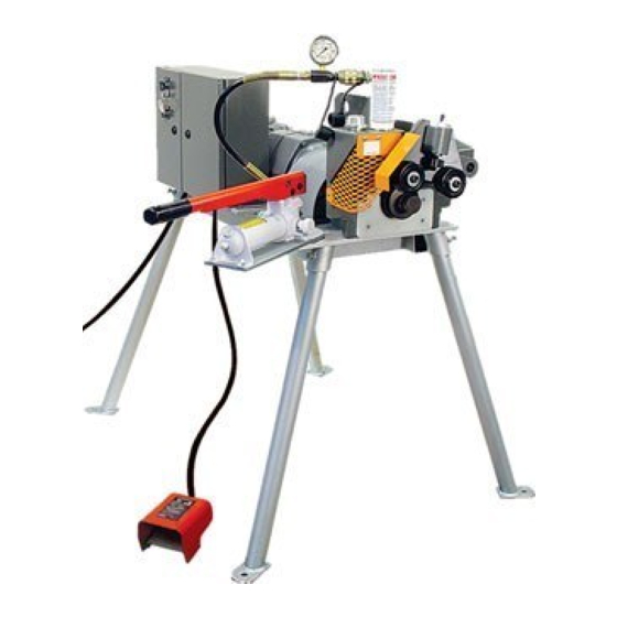
BUILDING CONNECTIONS THAT LAST GROOVER DESCRIPTION A. 3007 STANDARD EQUIPMENT A. 1007 STANDARD EQUIPMENT Roll Groover complete with groove and drive rolls for 2"-12" steel Roll Groover complete with groove and drive rolls for 2"- 12" steel pipe, pipe, Steel/CTS Dual Guide Roll Assembly, two stage hydraulic hand Steel/CTS Dual Guide Roll Assembly, one and one-half horsepower pump, mounting base with footed support legs for direct attachment electric motor drive with foot switch. -
Page 6: Groover Set-Up Model 1007
1007 & 3007 ROLL GROOVER Removal of the Groover from the shipping box and mounting of the support legs should be accomplished only with the aid of a hoist or other lifting device. To avoid possible injury DO NOT ATTEMPT TO LIFT THE MODEL 1007 ROLL GROOVER MANUALLY. CAUTION GROOVER SET UP MODEL 1007 Install a support leg tube into the receiving socket on the under side of the... -
Page 7: Groover Set-Up Model 3007
BUILDING CONNECTIONS THAT LAST THE GRUVLOK MODEL 3007 ROLL GROOVER IS DESIGNED FOR USE ® WITH A RIDGID 300 POWER DRIVE Removal of the Groover from the shipping box and mounting of the Groover to the Ridgid 300 drive should be accomplished by CAUTION 2 persons. -
Page 8: Pipe Set-Up And Positioning
1007 & 3007 ROLL GROOVER PIPE SET-UP AND POSITION - STEEL PIPE (MODEL 1007 & 3007) The Model 1007 and Model 3007 Groovers come with 2" through 6" IPS pipe size grooving rolls installed unless otherwise requested on your order. To change grooving rolls for other size(s) or for copper tube refer to page 13 for grooving rolls and guide roll plate changeout. - Page 9 BUILDING CONNECTIONS THAT LAST PIPE SET-UP AND POSITION - CTS COPPER SYSTEM (MODEL 1007 & 3007) To groove copper tube using the CTS Copper System, the Steel/CTS Dual Guide Roll Assembly must be used for all sizes of tube. (K, L, M, DWV). DO NOT use the Advanced Copper Method guide roll assembly when using the Copper CTS System. Failure to use the correct guide roll assembly will result in the tubing rolling out of the machine before a correct groove can be made.
-
Page 10: Setting Groove Diameter
1007 & 3007 ROLL GROOVER SETTING GROOVE DIAMETER - STEEL PIPE & CTS COPPER SYSTEM For proper set-up and positioning of pipe, refer to instructions as shown on page 9 Increase the pump pressure to the recommended set-up STEEL PIPE pressure shown in the chart for the size and wall thickness RECOMMENDED SET-UP PRESSURE (BOTH MODELS) pipe to be grooved. -
Page 11: Grooving The Pipe Or Tube
BUILDING CONNECTIONS THAT LAST GROOVING THE PIPE OR TUBE - STEEL PIPE Recheck for correct pipe Maintain grooving force set-up and position on the until the Knurled Stop (groove bottom roll and adjust as diameter stop) comes into required. Close the relief full, firm contact with the top valve on the hydraulic hand of the groover base head. - Page 12 1007 & 3007 ROLL GROOVER GROOVING THE PIPE OR TUBE - COPPER TUBE: CTS COPPPER SYSTEM Recheck for correct tube Maintain grooving force until set-up and position on the the Knurled Stop (groove bottom roll and adjust as diameter stop) comes into full, required.
-
Page 13: Grooving Roll Change
BUILDING CONNECTIONS THAT LAST GROOVING ROLL CHANGE - ROLL REMOVAL NOTE With 2"- 6" grooving rolls installed – remove the bottom roll first, then remove the top roll. With 8"- 12" and 14" - 16" grooving rolls installed – remove the top roll first, then remove the bottom roll. - Page 14 1007 & 3007 ROLL GROOVER GROOVING ROLL CHANGE - ROLL INSTALLATON NOTE With 2"- 6" grooving rolls – Install the top roll first, then install the bottom roll. With 8" – 12" and 14" – 16" grooving rolls – Install the bottom roll first, then install the top roll.
-
Page 15: Groover Maintenance
BUILDING CONNECTIONS THAT LAST NOTE GROOVING MAINTENANCE Due to the use of sealed bearings, the 1007 and 3007 Roll Groovers require very little maintenance. A. GENERAL 1. Pull the bottom roll shaft out the front of the Groover. 2. A protective film of light oil should be applied to all rollers and guide roll mounting plates. -
Page 16: Replacement Parts
1007 & 3007 ROLL GROOVER REPLACEMENT PARTS- 1007 & 3007 GROOVED HEAD 3 REQUIRED ID PART NAME PART NO ID PART NAME PART NO. ID PART NAME PART NO 10 Top Shaft GL11039 13 Depth Gauge: 1 Quick Release Pin GL11775 1"-3"... - Page 17 BUILDING CONNECTIONS THAT LAST REPLACEMENT PARTS - 1007 BASE ASSEMBLY 4 REQUIRED 4 REQUIRED 4 REQUIRED 4 REQUIRED 2 REQUIRED 4 REQUIRED 2 REQUIRED ID PART NAME PART NO ID PART NAME PART NO ID PART NAME PART NO 1 Pump Assembly GL11081 13 Gearbox Key GL11175...
- Page 18 1007 & 3007 ROLL GROOVER REPLACEMENT PARTS - 3007 BASE ASSEMBLY 2 REQUIRED 2 REQUIRED 2 REQUIRED 2 REQUIRED 2 REQUIRED 4 REQUIRED 2 REQUIRED ID PART NAME PART NO ID PART NAME PART NO ID PART NAME PART NO 1 Pump Assembly GL11081 1D Cap Screw,...
- Page 19 BUILDING CONNECTIONS THAT LAST REPLACEMENT PARTS - 1007 & 3007 STEEL AND COPPER GUIDE ROLL ASSEMBLIES ITEMS 1A, 1B 1C: 2 REQUIRED FOR STEEL 1 REQUIRED FOR CTS COPPER SYSTEM ID PART NAME PART NO ID PART NAME PART NO ID PART NAME PART NO 1 2"-12"...
-
Page 20: Groove Specifications
1007 & 3007 ROLL GROOVER GROOVE SPECIFICATION - STEEL GRUVLOK STANDARD ROLL GROOVE SPECIFICATIONS FOR STEEL & OTHER IPS SIZE PIPE Gasket Seat Groove Width Groove Diameter Groove Depth Nominal Min. Allow. Max. Pipe OD “A” “B” “C” “D” Wall Thickness Flare Pipe Size Actual... - Page 21 BUILDING CONNECTIONS THAT LAST GROOVE SPECIFICATION - CTS COPPER SYSTEM GRUVLOK CTS COPPER SYSTEM – ROLL GROOVE SPECIFICATIONS Tubing Outside Diameter Groove Diameter “C” Gasket Seat “A” Groove Width “B” Min. Max. Nominal Nominal Groove +/– 0.03 in. +0.03/–0.00 in. Wall Flare Tolerance...
-
Page 22: Troubleshooting
1007 & 3007 ROLL GROOVER TROUBLESHOOTING TROUBLESHOOTING INSTRUCTIONS Problem Possible Cause Solution Incorrect pipe positioning. See "Pipe Set-up & Positioning" Improper grooving technique. See "Grooving Pipe" Pipe will not stay in grooving rolls. Power drive running counterclockwise Ridgid 300 check setting in reverse Model 3007. - Page 23 BUILDING CONNECTIONS THAT LAST NOTES:...
- Page 24 BRANDS OF ANVIL INTERNATIONAL Anvil product lines include malleable and cast iron fittings, Anvil-Strut products include a complete line of channel in stock unions and flanges; seamless and welded steel pipe nipples; lengths of 10 and 20 feet, with custom lengths available upon steel pipe couplings;...
- Page 25 BUILDING CONNECTIONS THAT LAST The Gruvlok product line consists of couplings for grooved The Afcon seismic bracing line includes UL listed and FM approved and plain-end fittings, butterfly valves and check valves; structural attachments for concrete, wood or steel structural flanges;...
- Page 26 CUSTOMER SERVICE CENTERS Corporate Headquarters UNITED STATES TEL: 800-301-2701 FAX: Plants 708-534-5441 EMAIL: customerservice@anvilintl.com Regional Distribution Centers CANADA TEL: 800-661-8998 FAX: 519-426-5509 EMAIL: canadacs@anvilintl.com LATIN AMERICA TEL: +1-800-885-3000 FAX: +1-708-534-5441 EMAIL: latinoamerica@anvilintl.com INTERNATIONAL TEL: +31-53-572-5570 EMAIL: internationalsales@anvilintl.com REGIONAL Ontario, CA DISTRIBUTION CENTERS UNITED STATES...
- Page 27 North Kingstown, RI Columbia, PA Waynesboro, PA Tinley Park, IL Greencastle, PA Henderson, TN Guntersville, AL Irving, TX Houston, TX Orlando, FL ANVIL MAINTAINS CONTRACTS WITH A CORE FLEET OF CARRIERS TO PROVIDE EFFICIENTLY CONSISTENT DELIVERY SERVICES TO OUR CLIENTS.
- Page 28 F IRE PRO D U C T S www.anvilintl.com ©2018 Anvil International. All Rights Reserved. ANV_BRO_GV ROLL GROOVER 190205...
Need help?
Do you have a question about the GRUVLOK 1007 and is the answer not in the manual?
Questions and answers