
Related Manuals for Anvil Gruvlok 1007


Summary of Contents for Anvil Gruvlok 1007
- Page 1 1007 & 3007 Roll Groover Manual www.anvilintl.com NOVEMBER 2013 For the most current product/pricing information on Anvil products, please visit our website at www.anvilintl.com...
- Page 2 As an additional benefit to our customers, Anvil offers a complete and comprehensive Design Services Analysis for mechanical equipment rooms, to help you determine the most effective and cost-efficient piping solutions for your pipe system.
-
Page 3: Table Of Contents
IMPORTANT SAFETY NOTICE Carefully read and understand instructions before assembling and operating the Groover(s). Become thoroughly familiar with the Groover operation, usage and possible hazards specific to the Groover(s). TABLE OF CONTENTS SECTION I SECTION VIII - Groover Maintenance ....15 Safety Instructions ..........4 SECTION IX - Replacement Parts ..... -
Page 4: Safety Instructions
SECTION I - SAFETY INSTRUCTIONS CAUTION CAUTION - The Gruvlok Model 1007 and 3007 Roll Groovers are to be used only for roll grooving of pipe. These operating ® instructions pro vide important information for the safe operation of the Groovers to protect the operator from possible, serious injury. -
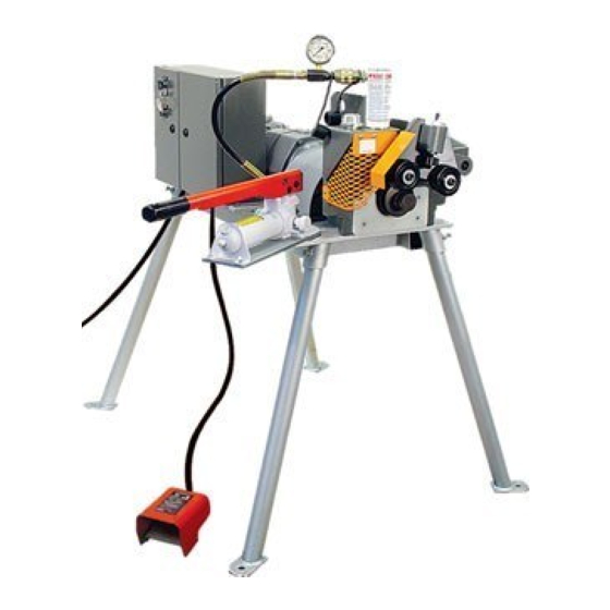
Page 5: Groover Description (Models 1007 & 3007)
SECTION II - GROOVER DESCRIPTION A. 1007 STANDARD EQUIPMENT - Roll Groover complete with groove A. 3007 STANDARD EQUIPMENT – Roll Groover complete with groove and drive rolls for 2" - 12" steel pipe, Steel/CTS Dual Guide Roll and drive rolls for 2" - 12" steel pipe, Steel/CTS Dual Guide Roll Assembly, one and one-half horsepower electric motor drive with Assembly, two stage hydraulic hand pump, mounting base with foot switch. -
Page 6: Groover Set-Up
SECTION III - GROOVER SET-UP CAUTION CAUTION - Removal of the Groover from the shipping box and mounting of the support legs should be accomplished only with the aid of a hoist or other lifting device. To avoid possible injury DO NOT ATTEMPT TO LIFT THE MODEL 1007 ROLL GROOVER MANUALLY. A. -
Page 7: B) Model 3007
SECTION III - GROOVER SET-UP THE GRUVLOK MODEL 3007 ROLL GROOVER IS DESIGNED FOR ® USE WITH A RIDGID* 300 POWER DRIVE. CAUTION CAUTION - Removal of the Groover from the shipping box and mounting of the Groover to the Ridgid 300 drive should be accomplished by 2 persons. -
Page 8: Pipe Set-Up And Positioning (Models 1007 & 3007)
SECTION IV - PIPE SET-UP AND POSITIONING (MODELS 1007 & 3007) The Model 1007 and Model 3007 Groovers come with 2" through 6" IPS pipe size grooving rolls installed unless otherwise requested on your order. To change grooving rolls for other size(s) or for copper tube refer to Section VII for grooving rolls and guide roll plate changeout. -
Page 9: B) Cts Copper System
SECTION IV - PIPE SET-UP AND POSITIONING (MODELS 1007 & 3007) To groove copper tube using the CTS Copper System, the Steel/CTS Dual Guide Roll Assembly must be used for all sizes of tube. (K, L, M, DWV). DO NOT use the Advanced Copper Method guide roll assembly when using the Copper CTS System. Failure to use the correct guide roll assembly will result in the tubing rolling out of the machine before a correct groove can be made. -
Page 10: Setting Groove Diameter (Models 1007 And 3007)
SECTION V – SETTING GROOVE DIAMETER (MODELS 1007 & 3007) STEEL PIPE and CTS COPPER SYSTEM For proper set-up and positioning of pipe, refer to instructions as STEEL PIPE shown in Section IV. ecommended ressure odels 1. Increase the pump pressure to the recommended set-up pressure Pipe Size Wall Set-up Pressure... -
Page 11: A) Steel Pipe
SECTION VI – GROOVING ThE PIPE OR TUBE (MODELS 1007 & 3007) A. STEEL PIPE 1. Recheck for correct pipe set-up and position on the bottom roll 4. Maintain grooving and adjust as required. Close the relief valve on the hydraulic hand force until the Knurled pump and increase pump pressure to 400 psi. -
Page 12: B) Cts Copper System
SECTION VI – GROOVING ThE PIPE OR TUBE (MODELS 1007 & 3007) B. COPPER TUBE: CTS COPPER SYSTEM 1. Recheck for correct tube set-up and position on the bottom roll 4. Maintain grooving and adjust as required. Close the relief valve on the hydraulic force until the Knurled hand pump and increase pump pressure to 100 psi. -
Page 13: Grooving Roll Change
SECTION VII – GROOVING ROLL ChANGE (MODELS 1007 & 3007) 1. ROLL REMOVAL Note: With 2" – 6" grooving rolls installed – remove the bottom roll first, then remove the top roll. With 8" – 12" and 14" – 16" grooving rolls installed – remove the top roll first, then remove the bottom roll. A. -
Page 14: Roll Installation
SECTION VII – GROOVING ROLL ChANGE (MODELS 1007 & 3007) 2. ROLL INSTALLATION Note: With 2" – 6" grooving rolls – Install the top roll first, then install the bottom roll. With 8" – 12" and 14" – 16" grooving rolls – Install the bottom roll first, then install the top roll. A. -
Page 15: Section Viii - Groover Maintenance
SECTION VIII - GROOVER MAINTENANCE Due to the use of sealed bearings, the 1007 and 3007 Roll Groovers require very little maintenance. A. GENERAL 3. Bleeding air from the system is necessary. 1. Periodically unplug and thoroughly clean your Roll Groover. Air can accumulate in the system through 2. -
Page 16: Section Ix - Replacement Parts
SECTION IX - REPLACEMENT PARTS A. 1007 & 3007 GROOVER HEAD 3 Req. ID No. Part Name ..........Part No. ID No. Part Name ..........Part No. Quick Release Pin ..........GL11775 Top Roller: Hydraulic Ram Assembly ........GL11095 2"-6" Steel .............. GL11110 Knurled Stop Assembly .......... -
Page 17: B) 1007 Base Assembly
SECTION IX - REPLACEMENT PARTS B. 1007 BASE ASSEMBLY 4 Req. 4 Req. 4 Req. 4 Req. 2 Req. 4 Req. 2 Req. ID No. Part Name ..........Part No. ID No. Part Name ..........Part No. Pump Assembly ............. GL11081 Electronic Control Panel ......... -
Page 18: C) 3007 Base Assembly
SECTION IX - REPLACEMENT PARTS C. 3007 BASE ASSEMBLY 2 Req. 2 Req. 2 Req. 2 Req. 2 Req. 4 Req. 2 Req. ID No. Part Name ..........Part No. ID No. Part Name ..........Part No. Pump Assembly ............. GL11081 Hex Bolt, ⁄... -
Page 19: D) 1007 & 3007 Steel & Copper Guide Roll Assemblies
SECTION IX - REPLACEMENT PARTS D. 1007 & 3007 STEEL AND COPPER GUIDE ROLL ASSEMBLIES Item 1A, 1B, 1C: 2 required for Steel 1 required for CTS Copper STEEL/CTS DUAL GUIDE ROLL ASSEMBLY ID No. Part Name ................Part No. 2"-12" Steel/CTS Dual Guide Roll Assembly ..........GL11100 Steel Guide Roll Assembly Consists of the Following: Guide Roll ....................GL11106 Washer,... -
Page 20: Section X - Groove Specifications
SECTION X – GROOVE SPECIFICATIONS GRUVLOK ROLL GROOVE SPECIFICATIONS ® ruvloK tandard roove pecifications & O IPS S teel ther Gasket Seat Groove Width Groove Diameter Groove Depth Nominal Min. Allow. Max. “D” Pipe OD “A” “B” “C” Wall Thickness Flare Pipe Size Actual... -
Page 21: B) Cts Copper System
SECTION X – GROOVE SPECIFICATIONS GRUVLOK CTS COPPER SYSTEM GROOVE SPECIFICATIONS ® cts c – r ruvloK opper ystem roove pecifications Tubing Outside Diameter Groove Diameter “C” Gasket Seat “A” Groove Width “B” Min. Max. Nominal Nominal Groove +/– 0.03 in. +0.03/–0.00 in. -
Page 22: Section Xi - Troubleshooting
SECTION XI – TROUBLEShOOTING roubleshooting nstructions Problem Possible Cause Solution Incorrect pipe positioning. See "Pipe Set-up & Positioning" Improper grooving technique. See "Grooving Pipe" Pipe will not stay in grooving rolls Power drive running counterclockwise Ridgid 300 check setting in reverse Model 3007. - Page 23 The product line encompasses variable spring hangers, constant supports, sway struts and snubbers as well as standard and North Alabama Pipe special design clamps. Anvil EPS brings the highest quality products Innovators of Pipe Fabrication Equipment Founded in 1983, NAP is a manufacturer of fabrication equipment,...
- Page 24 1401 Valley View Lane, Suite 150, Irving, TX 75061 Tel: 972-871-1206 Fax: 972-641-8946 Toll Free: 1-800-451-4414 caNada SERVicE cENtER anvil international canada Customer Service Center 390 Second Avenue, P.O. Box 40, Simcoe, Ontario N3Y 4K9 Tel: 519-426-4551 Fax: 519-426-5509 iNtERNatiONal SalES...
Need help?
Do you have a question about the Gruvlok 1007 and is the answer not in the manual?
Questions and answers