Sign In
Upload
Manuals
Brands
Hioki Manuals
Test Equipment
8861-50
Hioki 8861-50 Data Recorder Manuals
Manuals and User Guides for Hioki 8861-50 Data Recorder. We have
3
Hioki 8861-50 Data Recorder manuals available for free PDF download: Instruction Manual, Manual
Hioki 8861-50 Instruction Manual (490 pages)
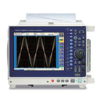
MEMORY HiCORDER
Brand:
Hioki
| Category:
Data Loggers
| Size: 10 MB
Table of Contents
Table of Contents
3
Contents 1
13
Usage Index
13
Introduction
15
Reading this Manual
17
Chapter 1 Overview
19
Product Overview
19
Features
19
Interconnection and Block Diagrams
22
Chapter 2 Operating Keys and Screen Contents
25
Operating Keys
25
Screen Organization
29
Opening Screen
30
Waveform Screen
31
Settings Screen
39
Status Settings Screen
40
Channel Settings Screen
44
Trigger Settings Screen
47
Sheet Settings Screen
48
Memory Division Settings Screen
49
Numerical Calculation (Num Calc) Settings Screen
50
Waveform Calculation (Wave Calc) Settings Screen
51
Save Settings Screen
52
Print Settings Screen
53
File Screen
54
System Screen
57
Environment (Env) Settings Screen
57
Communication (Comm) Settings Screen
58
External Terminals (Ext Term) Settings Screen
61
Setting Configuration (Setting) Screen
62
Initialization (Init) Settings Screen
63
Configuration List (Config) Screen
64
Chapter 3 Operation Overview
65
Measurement Workflow
65
Analog Waveform Recording
65
Logic Waveform Recording
69
Before Operating
70
Preliminary Settings and Verification
70
Using a Mouse
70
Using a Keyboard
71
If the Model 9719-50 Memory Backup Unit Is Installed
72
If the Model 9684 DC Power Unit Is Installed
73
Common Operations
75
Select a Function
75
To Change a Setting
75
Entering Text and Numbers
77
Mouse Operations
81
Automatic Range Setting (Auto-Ranging Function)
86
Starting and Stopping Measurement
88
Disabling Key Operations (Key-Lock Function)
90
Chapter 4 Measurement Configuration Settings
91
Selecting the Function
93
Setting Measurement Configuration (Status Settings Screen)
98
Selecting Channels to Use
98
Setting the Timebase (Horizontal Axis) and Sampling Rate
102
Setting Different Sampling Rates
106
Setting the Recording Length (Number of Divisions)
109
Acquiring Waveforms Using the Utility Functions
114
Displaying Waveforms During Recording (Roll Mode)
114
Overlaying Waveforms
116
Averaging Waveforms
118
Dividing Memory
121
Setting Measurement Configuration on the Waveform Screen
126
Chapter 5 Input Channel Settings
127
Analog Channel Settings
128
Adding Comments
130
Adding a Title Comment
130
Adding Channel Comments
131
Monitoring Input Status
134
Verifying the Input Level (Level Monitor)
134
Converting Input Values (Scaling Function)
135
Verifying and Setting All Channels from a List
141
Copying Settings between Channels
145
Setting Input Channels from the Waveform Screen
146
Chapter 6 Trigger Settings
147
About Triggering
148
Setting Workflow
149
Setting the Trigger Mode
150
Setting Combining Logic (AND/OR) for Multiple Trigger Sources
151
Pre-Trigger Settings
152
Setting the Trigger Start Point (Pre-Trigger)
152
Setting Trigger Acceptance (Trigger Priority)
155
Setting Trigger Timing
156
Triggering by Analog Signals
158
About Analog Trigger Types and Settings
158
(Level Trigger)
162
Triggering with Upper and Lower Thresholds (Window Trigger)
164
Triggering by Period Variance (Period Trigger)
165
Triggering by Pulse Width (Glitch Trigger)
167
Triggering by a Variance Within a Specified Interval (Slope Trigger)
168
Triggering Upon Instantaneous Voltage Sag at
170
Mains Frequency (50/60 Hz) (Voltage Sag Trigger)
170
Triggering by Logic Signals (Logic Trigger)
171
Trigger by Timer or Time Intervals (Timer Trigger)
174
Triggering Manually (Manual Trigger)
177
Applying an External Trigger (External Trigger)
178
Making Trigger Settings on the Waveform Screen
179
Chapter 7 Waveform Display Settings
181
Making Input Waveform Display Settings (Analog Waveforms)
182
Setting Whether a Waveform Is Displayed or Hidden, and Its Color
183
Setting the Waveform Display Position (Zero Position)
184
Setting the Screen Layout of the Waveform Screen (Sheet Settings Screen)
186
Assigning Display Data to Sheets
187
Assigning a Sheet Name
189
Setting the Display Type
189
Splitting the Display Screen (Split-Screen)
190
Setting Waveform Scrolling Orientation
192
Assigning Display Channels to Graphs (Analog Channels)
193
Displaying Logic Waveforms
195
Setting the Waveform Display
196
Setting the Display Position
197
Setting the Display Height
198
Composite Waveforms (X-Y Waveforms)
199
Chapter 8 Waveform Screen Monitoring and Analysis
203
Scrolling Waveforms
204
Verifying Waveform Display Position
206
Specifying a Display Location (Jump Function)
207
Displaying Measured Values and Information
208
Applying Gauges
210
Monitoring Input Levels (Level Monitor)
211
Specifying a Waveform Range
212
Cursor Values
214
About Cursor Types and Values
214
Reading Time and Frequency (Vertical Cursors)
216
Reading Voltage Values (Horizontal Cursors)
218
Reading Time and Voltage Values (Trace Cursor)
219
Reading Cursor Values of X-Y Waveforms
221
Magnifying and Compressing Waveforms
223
Magnifying and Compressing Horizontally (Time Axis)
223
Magnifying and Compressing Vertically (Voltage Axis)
224
Magnifying a Section of the Horizontal Axis (Time Axis - Zoom Function)
225
Setting Arbitrary Waveform Height and Position on the Vertical (Voltage) Axis (Variable Function)
227
Fine Adjustment of Input Values (Vernier Function)
230
Viewing Past Waveforms
231
Viewing Waveforms in Every Display Block (Memory Division)
232
Viewing Waveform Data as Numerical Values
233
Searching a Waveform
234
Searching by Trigger Criteria
235
Searching by Time
240
Searching for Peaks
241
Inserting and Searching for Event Marks on a Waveform
243
Inserting Event Marks
243
Event Mark Searching
244
Event Mark Editing
245
Chapter 9 Measuring with Real-Time Saving
247
Overview of the Real-Time Saving Function
247
Setting and Analysis Workflow
249
Pre-Measurement Settings
254
Analyzing Data
260
Waveform Viewing
260
Calculating
264
Chapter 10 Long-Term Monitoring and Instantaneous Recording
265
Overview of the REC&MEM Function
265
Setting and Analysis Workflow
266
Analyzing Data
270
Waveform Viewing
270
Calculating
272
Chapter 11 Saving/Loading Data & Managing Files
273
Storage Media
274
Using a PC Card
274
Using a Hard Disk
275
Using USB Memory Devices
275
Using a Network Shared Folder
276
Initializing (Formatting) Storage Media
278
Data Capable of Being Saved & Loaded
279
Saving Data
284
Save Sequence
284
Save Methods
285
Specifying the Save Destination
287
Setting Auto Save
288
Setting Manual Save (SAVE Key Output)
290
Saving Settings Data
292
Automatically Saving Waveforms
294
Optionally Selecting Waveforms & Saving (SAVE Key)
297
Automatically Saving Display Images
299
10Optionally Selecting Display Screens & Saving (SAVE Key)
301
11Saving an Event Mark List
302
Loading Data
303
Selecting Files & Folders on Storage Media
304
Loading Settings Data
306
Loading Waveform Data
307
Saving & Loading Auto Settings File (Auto Setup Function)
308
Examples of Saving Data: Reading Data on a PC
310
Example of Saving Data
310
Reading Waveform Data on a PC
314
Managing Files
316
Copying Files & Folders
317
Moving Files & Folders
318
Deleting Files & Folders
319
Renaming Files & Folders
319
Creating New Folders
320
Sorting Files
321
Limiting Display of Files
322
Setting the Items to Display
323
Printing the File List
324
Chapter 12 Printing
325
Printing Workflow
326
Print Methods and Print Items
327
Making Auto Print Settings
329
Making Manual Print (PRINT Key Output) Settings
331
Making Printer Settings
335
Internal Printer Settings
335
External Printer Settings
337
Setting the Print Content
339
Common Settings
339
Printing Waveforms
341
Printing Numerical Value Displays
346
Making Gauge Settings (When Using External Printer)
348
Printing Comments and Setting Data
349
Print Examples
351
Chapter 13 System Environment Settings
361
Making Waveform Screen Display Settings
362
Selecting the Grid Type
362
Displaying or Hiding Comments
363
Selecting the Time Value Display
364
Displaying Zero Position
364
Making Key Operation and Operational Settings
365
Specifying Activation Conditions for the START Key
365
Setting the Method for Stopping Measurement with the STOP Key
366
Using the Auto-Resume Function (Resume after Power Restoration)
367
Specifying Jog & Shuttle Scroll Operations
368
Using Sheet Scroll Linkage
369
Specifying SHEET/PAGE Key Operations
369
Selecting How Settings Affect Measurement (Restart Permission)
370
Performing Variable Function Auto Adjustment
370
Specifying Beep and Operation Sounds
371
10Making Screen Saver Settings
372
11Making Backlight Saver Settings
373
12Selecting the Display Language
374
13Selecting Screen Colors
375
Making System Settings
376
Setting the Date and Time
376
Initializing Waveform Data
377
Initializing System Settings (System Reset)
378
Self-Test (Self Diagnostics)
379
Adjusting the 8958 16-Ch Scanner Unit
385
System Configuration List
386
Chapter 14 External Control
387
Connecting External Control Terminals
388
External I/O
390
External Trigger Input ( EXT TRIG )
390
Trigger Output ( TRIG out /CAL)
392
External Sampling (EXT.SMPL)
394
Synchronized Sampling Output (SYNC.OUT)
396
GO/ NG Evaluation Output ( GO / EXT OUT1 )
399
Ng Ext Out2
401
External Output ( GO / EXT OUT1 )
401
GO/ NG Evaluation Output ( GO / EXT OUT1 )/ ( NG / EXT OUT2 )
402
Start Ext.in1 Stop Ext.in2 )/( Print / Ext.in3 )
403
Probe Calibration Signal Output ( TRIG out /CAL)
405
Chapter 15 Specifications
407
General Specifications
407
Trigger Section
413
Memory Function
415
Recorder Function
417
REC&MEM Function
419
FFT Function
422
Real-Time Saving Function
423
Functions
424
Practical Functions
424
Miscellaneous Functions
424
Advertisement
Hioki 8861-50 Manual (114 pages)
INPUT MODULE MEMORY HiCORDER
Brand:
Hioki
| Category:
I/O Systems
| Size: 1 MB
Table of Contents
Table of Contents
5
Introduction
9
Structure of this Document
11
Chapter 1 Overview
13
Product Overview
13
Input Module Usage List
17
List of Input Modules, Cables, Probes and Clamp Combinations
19
Chapter 2 Connections
21
Installing Input Modules (Adding or Replacing)
22
Connecting the Cables
24
Connection Preparations
24
Connecting to an Analog Unit (Models 8936, 8938, 8946, 8956 and 8957)
25
Connecting to the Model 8937 Voltage/Temp Unit
26
Connecting to a Strain Unit (Models 8939 and 8960)
28
Connecting to the Model 8940 F/V Unit
29
Connecting to the Model 8947 Charge Unit
32
Connecting to the Model 8958 16-Ch Scanner Unit
34
Connecting to the Model 8959 DC/RMS Unit
36
Connecting Clamps
37
Connecting a Differential Probe
39
Connecting Attenuating Probes
43
Connecting Logic Probes
45
Supplying Power from the Model 9687 Probe Power Unit
49
Chapter 3 Input Channel Settings
51
Analog Unit Settings (Models 8936, 8946 and 8956)
52
Model 8937 Voltage and Temperature Unit Settings
53
Voltage Measurement
53
Temperature Measurement
54
Model 8938 FFT Analog Unit Settings
56
Strain Unit Settings (Models 8939 and 8960)
57
Model 8940 F/V Unit Settings
58
Measuring Frequency, 50/60 Hz and Rotation Rate
58
Pulse Count Measurement
60
Pulse Duty Measurement
61
Voltage Measurement
62
Current Measurement
63
Model 8947 Charge Unit Settings
64
Voltage Measurement
64
Acceleration Measurement (Charge, Preamp)
65
Model 8957 High Resolution Unit Settings
67
Model 8958 16-Ch Scanner Unit Settings
68
Voltage Measurement
68
Temperature Measurement
69
Model 8959 DC/RMS Unit Settings
71
About Setting Contents
72
Measurement Range Setting
72
Setting Input Coupling
73
Low-Pass Filter (LPF) Settings
74
Anti-Aliasing Filter (AAF) Settings
75
Digital Filter (Digital F) Settings
75
Thermocouple (Sensor) Type Setting
76
Reference Junction Compensation Setting
76
Drift Correction Setting
77
Disconnect (Burn-Out) Detection Setting
77
Hold Setting
78
Pull-Up Setting
79
Threshold Setting
80
Response (Timing) Setting
80
Sensor Sensitivity Setting
81
Probe Attenuation Selection
83
Bridge Voltage Setting
83
Executing Zero Adjustment
84
Executing Offset Cancellation
84
Executing Auto-Balance
86
Chapter 4 Logic Input Settings
87
Operation Overview
87
Setting Procedure
88
Chapter 5 Specifications
91
Logic Input Section
91
Model 9327 Logic Probe
91
Model 9321-01 Logic Probe
92
Model 9320-01 Logic Probe
93
Analog Input Section
94
Model 8936 Analog Unit
94
Model 8937 Voltage/Temp Unit
96
Model 8938 FFT Analog Unit
98
Model 8939 Strain Unit
99
Model 8940 F/V Unit
100
Model 8946 4-Ch Analog Unit
102
Model 8947 Charge Unit
103
Model 8956 Analog Unit
105
Model 8957 High Resolution Unit
106
Model 8958 16-Ch Scanner Unit
107
Model 8959 DC/RMS Unit
109
Model 8960 Strain Unit
110
Index
111
Hioki 8861-50 Manual (16 pages)
MEMORY HiCORDER
Brand:
Hioki
| Category:
Test Equipment
| Size: 4 MB
Advertisement
Advertisement
Related Products
Hioki 8860-50
Hioki MEMORY HiCORDER 8855
Hioki 8807-51
Hioki 8808-51
Hioki 8807-01
Hioki 8808-01
Hioki 8860
Hioki 8861
Hioki 8826
Hioki 8841
Hioki Categories
Measuring Instruments
Test Equipment
Data Loggers
Multimeter
Accessories
More Hioki Manuals
Login
Sign In
OR
Sign in with Facebook
Sign in with Google
Upload manual
Upload from disk
Upload from URL