
Related Manuals for MXN MXN-7DM


Summary of Contents for MXN MXN-7DM
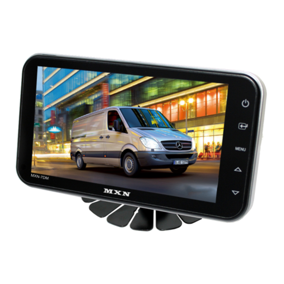
- Page 1 OWNER’S MANUAL 7” Digital LCD monitor for allround vision MXN-7DM Model : MXN-7DM Design and Specifications are subject to change without notice.
-
Page 2: Table Of Contents
Model : MXN-7DM INDEX Safety Instructions ..03 Package Contents ..04 Operation ..05 System Setting ..07~12 Camera setting ..07 Trigger setting ..08 Auto Scan setting ..10 Day/Night setting ..10 Advanced menu ..11 Installation .. -
Page 3: Safety Instructions
Safety Instructions WARNING To avoid electric shock, do not open the cabinet. Refer servicing to qualified personnel only. CAUTION RISK OF ELECTRIC SHOCK DO NOT OPEN CAUTION: TO REDUCE THE RISK OF ELECTRIC SHOCK, DO NOT REMOVE COVER (OR BACK). NO USER-SERVICEABLE PARTS INSIDE. -
Page 4: Package Contents
Package Contents MONITOR CAMERA INPUT CABLE OWNER’S MANUAL 7” Digital LCD monitor for allround vision MXN-7DM Model : MXN-7DM Design and Specifications are subject to chage without notice. (RAIL TYPE) FIXING BRACKET USERS MANUAL SUNVISOR SCREW KIT - 4 -... -
Page 5: Operation
Operation POWER SELECT MENU DOWN DAY/NIGHT SENSOR POWER Touch icon to turn the monitor on. Touch icon to turn the monitor off. * NOTE - Monitor start mode will follow “AUTO POWER ” setting. SELECT icon to select CAMERA. Touch icon to select the option in SET UP MENU. - Page 6 Operation DISPLAY MENU MENU MENU UP/DN SELECT UP/DN MENU Short Key (more than Touch 1 sec) BRIGHT -DISPLAY MENU- 1. BRIGHT [30] 2. CONTRAST [30] CONTRAST 3. COLOR [30] 4. SHARPNESS [30] 5. TINT COLOR SHARPNESS NTSC MODE TINT * "TINT" menu is displayed in NTSC only. Shortkey Menu can control Bright, Contrast, Color and Sharpness, Tint for individual channel ( CAM1, CAM2 ) How to adjust : Select camera ( CAM1, CAM2 ) and press the “Menu”...
-
Page 7: System Setting
System Setting SETUP MENU Touch MENU icon for a while (over 2 sec) to enter MAIN MENU. Selectable OSD MENU disappears within 10 sec if there is no new icon touched. -MAIN MENU- MENU 1. CAMERA SETTING MENU UP/DN SELECT 2. -
Page 8: Trigger Setting
System Setting 2. TRIGGER SETTING 2. TRIGGER SETTING TRIGGER1 SOURCE [CAM 1 ] DELAY [02sec MARKER [A;B;OFF] MARKER SETTING SOURCE: [CAM1 => CAM2 => SKIP] Trigger1,2 UP/DN selecting option setting exit User can use 2 triggers and each trigger source (CAM1,2) can be selected. When the trigger is activated, the selected source's image is displayed. - Page 9 System Setting MARKER:[A;B;OFF] Trigger1,2 UP/DN MARKER SELECT selecting option selecting MARKER SETTING MARKER SETTING UP / DN SELECT UP / DN SELECT UP / DN shifting selecting shifting option setting selecting exit LEFT-RIGHT UP-DOWN WIDTH LEFT NARROW RIGHT DOWN WIDE DOWN - 9 -...
-
Page 10: Auto Scan Setting
System Setting 3. AUTO SCAN SETTING 3. AUTO SCAN SETTING AUTO SCAN [ ON;OFF CAM1 SCAN TIME [0~20sec CAM2 SCAN TIME [0~20sec AUTO SCAN TIME SETTING UP / DN SELECT UP / DN SELECT MENU shifting option setting shifting option setting exit AUTO SCAN:[ON;OFF] UP / DN... -
Page 11: Advanced Menu
System Setting 5. ADCANCED MENU AUTO POWER:[ON;AUTO;OFF] 5. ADVANCED MENU AUTO POWER [ON;AUTO;OFF] SPEED SWITCH FACTORY RESET UP / DN SELECT MENU shifting option setting exit * NOTE - Auto Setting Monitor keeps the last setting in memory: Monitor will start up "Power-on" mode or "Stand- by"... - Page 12 System Setting EXAMPLE OF SPEED SWITCH FUNCTION: * The orange wire needs to be connected with the vehicle’s tacho signal and via MENU the SPEED SWITCH needs to be selected ON. * Adjust FREQUENCY into 67Hz. At this setting (and most common used tacho signal), the selected camera will be displayed during a speed of 0~33km/h.
-
Page 13: Installation
Installation 1. Monitor Fixing Method 1) STAND BRACKET ,RAILS TYPE(INCLUDED) 2) ROOF MOUNT BRACKET : OPTION 3) WINDOW BRACKET: OPTION 2. Sunvisor Mounting Method - 13 -... -
Page 14: Connection
Connection POWER/TRIGGER WIRE FUNCTIONS REF# WIRE COLOR DESCRIPTION POWER IN DC (12 TO 30V) WHITE TRIGGER2 (12 TO 30V) GREEN TRIGGER1 (12 TO 30V highest priority) ORANGE SPEED SWITCH (TACHO SIGNAL) BLACK GROUND (POWER 12 TO 30V, via ignition) FUSE (3A) BLACK (GROUND) -
Page 15: Specifications
Panel 7" Digital Resolution 800 (H) x 480 (V) x 3 (RGB) Format 16:9 wide Camera input(2CH) Mini DIN 4P, 1Vp-p 75Ω (MXN configuration) Operating Temp. -30℃ ~ +80℃ Storage Temp. -40℃ ~ +90℃ Vibration OSD Control Day & Night Sensor & Sharpness... - Page 16 THIS SYMBOL MEANS DO NOT DISPOSE OF AS MUNICIPAL WASTE. RE-USE OR RECYCLE WHEREVER POSSIBLE. ELECTRICAL / ELECTRONIC COMPONENTS MAY CONTAIN SUBSTANCES WHICH ARE HARMFUL TO THE ENVIRONMENT. FOR ENVIRONMENTALLY SOUND METHODS OF DISPOSAL, PLEASE CONTACT YOUR LOCAL printed in korea GOVERNMENT AUTHORITY.
Need help?
Do you have a question about the MXN-7DM and is the answer not in the manual?
Questions and answers