Table of Contents
Advertisement
Available languages
Available languages
ENGLISH .......................................................................... 1
SVENSKA ...................................................................... 14
NEDERLANDS ................................................................ 25
DANSK .......................................................................... 37
WARRANTY ................................................................... 50
TEMPLATES ................................................................... 51
© 2008-2015 Tru-Test Limited
All product names and brand names in this document are trademarks or registered trademarks of their
respective holders.
No part of this publication may be photocopied, reproduced, stored in a retrieval system, or transmitted in
any form or by any means, electronic, mechanical, photocopying, recording or otherwise without the prior
written permission of Tru-Test Limited. Product specifications may change without prior notice.
For more information on other quality Tru-Test Group brands and products, visit www.tru-test.com.
Postal address:
Tru-Test Limited
25 Carbine Road
P O Box 51078
Mt Wellington
Pakuranga
Auckland 1060
Auckland 2140
New Zealand
New Zealand
Tru-Test Ltd thanks the International Electrotechnical Commission (IEC) for permission to reproduce
Information from its International Publication 60335-2-76 ed.2.2 (2013). All such extracts are copyright of
IEC, Geneva, Switzerland. All rights reserved. Further information on the IEC is available from www.iec.ch.
IEC has no responsibility for the placement and context in which the extracts and contents are reproduced
by the author, nor is IEC in any way responsible for the other content or accuracy therein.
829767 Issue 1 (to be supplied to Continental Europe [only] with 816260) 08/2015
ENGLISH
Electric fencing and your energizer
Congratulations on the purchase of your energizer. This product has
been constructed using the latest technology and construction
techniques. It has been engineered to give superior performance and
many years of service.
It is important to read these instructions carefully and thoroughly. They
contain important safety information and will assist you in ensuring that
your electric fencing system gives maximum performance and reliability.
How does an electric fence work?
An electric fence system comprises an energizer and an insulated fence.
The energizer puts very short pulses of electricity onto the fence line.
These pulses have a high voltage, but are of very short duration (less
than 3/10,000ths of a second). However, a shock from an electric fence
pulse is very uncomfortable and animals quickly learn to respect electric
fences. An electric fence is not only a physical barrier, but is also a
strong psychological barrier.
What are the benefits of an electric fence?
An electric fence has many benefits over conventional fencing:
Requires less labour and materials to construct.
•
Flexibility to change or add paddocks when required. The use of
•
strip grazing techniques can allow temporary fencing to be quickly
and easily erected or removed.
Controls a broader range of animals.
•
Minimises damage to expensive livestock when compared with
•
other fencing mechanisms, for example barbed wire.
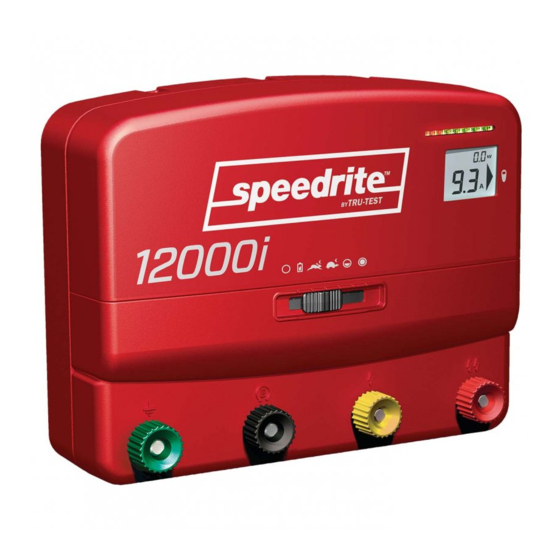
Models covered by this manual
This manual covers various energizer models:
12000i, X12i,
12 J energizers. These energizers have an LCD display,
412i
an earth monitoring feature and remote control
capabilities.
6000i, X6i, 406i
6 J energizers. These energizers have an LCD display, an
earth monitoring feature and remote control
capabilities.
6000i-EU, X6i-EU,
6 J energizers sold in Europe. These energizers have an
406i-EU
LCD display, an earth monitoring feature and remote
control capabilities. If the energizer detects a sudden
increase in the load on the fence, a warning is issued.
The energizer may increase its output power to more
effectively energise the fence.
6000, X6, 406
6 J energizers.
6000-EU, X6-EU,
6 J energizers sold in Europe. If the energizer detects a
406-EU
sudden increase in the load on the fence, a warning is
issued. The energizer may increase its output power to
more effectively energise the fence.
Note:
The energizers listed here may not be available in all markets.
Key to symbols on the energizer
Fence earth terminal. Connect the fence earth terminal to the
energizer earth system.
Fence earth monitor terminal
EU, X6i, X6i-EU, 406i and 406i-EU energizers only).
fence earth monitor terminal to a separate earth rod. See
monitoring
on page 5.
Fence half voltage terminal. For use in areas with poor earthing,
Bi-polar installation
see
fence voltage is desirable (e.g. where fire risk is present or where
there is a risk of someone touching the fence), see
fence voltage output
on page 9. Connect the fence half voltage
terminal to the fence.
Fence full voltage terminal. Connect the fence full voltage terminal
to the fence.
Risk of electric shock! This energizer should be opened or repaired
only by qualified personnel.
Read full instructions before use.
(12000i, X12i, 412i, 6000i, 6000i-
Connect the
on page 8 or in areas where a limit of 5 kV
Reducing the
Earth
1
Advertisement
Table of Contents

Related Manuals for Tru-Test Unigizer 12000i

Summary of Contents for Tru-Test Unigizer 12000i
- Page 1 Tru-Test Limited. Product specifications may change without prior notice. capabilities. For more information on other quality Tru-Test Group brands and products, visit www.tru-test.com. 6000i, X6i, 406i 6 J energizers. These energizers have an LCD display, an...
- Page 2 This symbol on the product or its packaging indicates that this Warning! product must not be disposed of with other waste. Instead, it is - USA and Canada - To reduce the risk of electric shock, the your responsibility to dispose of your waste equipment by handing energizer’s power adaptor may have a polarized plug (one blade is it over to a designated collection point for the recycling of waste wider than the other).
-
Page 3: Installation
Installation Installing the energizer indoors The energizer must be installed indoors, (under cover) when being Read all of the safety instructions in this manual and any relevant powered by mains/line power. government, regional and local safety standards before installing the energizer. -
Page 4: Operation
(only required for advanced troubleshooting and service. For more information about solar installations, refer to servicing). After this, the energizer resumes normal operation. In poor www.tru-test.com. light conditions, when the selector switch position is changed, the LCD display illuminates for 20 seconds. - Page 5 Using the selector switch If you see only red lights at each pulse and no green lights, your fence line is very heavily loaded, and you will need to look for faults on the Frequently asked questions/Troubleshooting fence line. See on page 11.
-
Page 6: Battery Selection And Management
Setting up for earth monitoring 11.7-12.0 V Low battery charge voltage (20-50%): The earth monitoring feature works by comparing the voltage of the energizer’s earth system with that of a separate earth rod. Ensure the • Monitor battery separate earth rod is at least 10 m (33’) away from any other earth voltage. - Page 7 530 mA (24 900 mA (24 hour 12000i, X12i, 412i, 6000i, 6000i-EU, X6i, X6i-EU, 406i, and 406i-EU hour average) average) energizers will accept commands from a Tru-Test remote control 330 mA 580 mA 85 Ah 150 Ah handset. No configuration is required. The energizer and remote control are pre-programmed to communicate.
-
Page 8: Building A Permanent Electric Fence
Activating the energizer for use with a remote control Other useful components that can be added: handset Cut-out switches. Installed at regular intervals, these allow you to isolate sections of the fence for repair. During the first 10 minutes of operation, the energizer’s remote control feature can be activated. - Page 9 Reducing the fence voltage output End assemblies In some areas, it may desirable to have a reduced fence voltage output, Angle stay for example where there is a risk of fire or where there is a chance that people might come into contact with the electric fence (e.g. around a Suitable for field gate, high-tension strainer.
-
Page 10: Safety Considerations
At least 100 m (330’) away from the energizer, short circuit the Fence circuit – All conductive parts or components within an energizer fence by laying several steel rods or lengths of pipe against the that are connected or are intended to be connected, galvanically, to the fence. -
Page 11: Frequently Asked Questions/Troubleshooting
Care must be taken to avoid damage to the connecting leads due to the Important safety instructions for Class 2 power units effects of animal hooves or vehicle wheels sinking into the ground. (USA/Canada only) Connecting leads shall not be installed in the same conduit as the When using electrical products, basic precautions should always be mains supply wiring, communication cables or data cables. - Page 12 use the procedure described in Installing and testing an earth system If... This means that... page 9. (6000i-EU, X6i-EU, 406i-EU, The energizer has detected a sudden Check the fence system for faults. The most common source of low 6000-EU, X6-EU and 406-EU increase in the load on the fence.
-
Page 13: Product Specifications
Servicing This energizer uses Double Insulation, where two systems of insulation are provided instead of grounding. No equipment grounding means is provided in the supply cord of a double-insulated energizer, nor should a means for equipment grounding be added to the energizer. Servicing a double-insulated energizer requires extreme care and knowledge of the system and should only be done by qualified service personnel. - Page 14 SVENSKA Förklaring av symboler på aggregatet Stängslets jordningsuttag. Anslut stängslets jordningsuttag till Elstängsel och ditt aggregat aggregatets jordningssystem. (endast aggregat 12000i, Stängslets jordningsövervakningsuttag Gratulerar till ditt köp av aggregatet. Produkten har konstruerats enligt X12i, 412i, 6000i, 6000i-EU, X6i, X6i-EU, 406i och 406i-EU). den senaste teknologin och konstruktionstekniken.
- Page 15 Aggregatets delar Installation Använda strömadaptern och batteristift Aggregatet försörjs med en strömadapter (för anslutning till nät- Läs igenom alla säkerhetsinstruktioner i bruksanvisningen och alla /ledningsström) och en uppsättning batteristift (för anslutning till ett relevanta gällande nationella, regionala och lokala säkerhetsstandarder batteri).
- Page 16 OBS! Om aggregatet installeras inomhus kan det försörjas med ett För mer information om solpanelsinstallationer, se www.tru-test.com. batteri istället för el från eluttaget, om nödvändigt. Varning! Försörj inte aggregatet med el från eluttaget om det installeras utomhus.
- Page 17 Anslut stängslet till jordningsuttaget (grönt) på aggregatets Långsam hastighet - dag Aggregatet drivs med långsam jordningssystem. Snabb hastighet - natt hastighet (2,5 sekunder mellan pulser) Endast aggregat 12000i, X12i, 412i, 6000i, 6000i EU, X6i, på dagen och snabb hastighet (1,5 EU, 406i och 406i Om jordningsövervakning önskas, sekunder mellan pulser) på...
- Page 18 Endast aggregat 6000i EU, X6i EU, 406i EU, 6000 EU, X6 EU och jordledningssystem på sidan 15 för information om hur ett jordledningssystem installeras på ett effektivt sätt. Om aggregatet detekterar att belastningen plötslig ökar på stängslet börjar en varningslampa blinka ( ), pulshastigheten minskar och en Test av batteriets spänning varningsklocka ljuder i upp till 10 minuter.
- Page 19 Fyll på batteriet med destillerat vatten. Fyll inte på för mycket. Se • i solpanelsinstallationen. För mer detaljerad information, se vidare i batteritillverkarens rekommendationer för mer www.tru-test.com. information.
- Page 20 • 406i-EU tar emot kommandon från en fjärrkontrollerad handenhet från plast, lämpliga för användning underjord eller genom väggar. Tru-Test. Ingen konfigurering krävs. Aggregatet och fjärrkontrollen har Används till att ansluta aggregatet till jordledningen och stängsel. förprogrammerats för kommunikation. Ett isolerat stängsel.
- Page 21 Konstruera ett bipolärt stängsel: 15 m mellanrum med mellanstolpar Sammanlänka stängseltrådar så att det finns två olika kretsar, enligt diagrammet. Anslut stängslets lågspänningsuttag (gult) till jordningssystemet med en isolerad kabel. Anslut stängslets jordningsuttag (grönt) till de negativa trådarna. Anslut stängslets fullspänningsuttag (rött) till de positiva trådarna. Otämjda djur 7-trådars, 10 m mellanrum med mellanstolpar Observera:...
- Page 22 Installation och testning av jordledningssystem Ett exempel på ett temporärt stängsel visas nedan. Välj en lämplig plats för jordledningssystemet. Platserna måste vara: minst 10 m från andra jordledningssystem (t.ex. telefon, kraftnät • eller jordledningssystem från ett annat aggregat). på avstånd från boskap eller annan trafik som kan störa •...
- Page 23 För två olika eldjurstängsel, som vart och ett matas från olika aggregat fästa på stängselstakarna eller ordentligt fastklämda på med oberoende tidsinställning, ska avståndet mellan trådarna på de två stängseltrådarna. eldjurstängslen vara minst 2,5 m. Om detta mellanrum ska slutas ska Storleken på...
- Page 24 Inga lampor blinkar på aggregatet. Om... Betyder det att... Se till att strömmen är påkopplad. Kontrollera om det är fel på (Endast aggregat 12000i, Batterispänningen är dålig. Kontrollera stängselsystemet (se ovan). Kontrollera aggregatet (se ovan). Om X12i, 412i, 6000i, genast batteriets spänning med aggregatet fortfarande inte fungerar kan det behöva servas.
-
Page 25: Warranty
Details van garantieperiodes en andere van toepassing zijnde voorwaarden zijn Nærmere oplysning om garantiperioden og andre relevante enkeltheder findes hos forhandleren verkrijgbaar bij de zaak waar u het product heeft gekocht of bij www.tru-test.com. eller på hjemmesiden www.tru-test.com. N.B.:... - Page 26 6 J Unigizer 130 mm (5 1/8”) 216 mm (8 1/2”)
- Page 27 12 J Unigizer 170 mm (6 3/4”) 225 mm (8 7/8”) 222 mm (8 3/4”)
Need help?
Do you have a question about the Unigizer 12000i and is the answer not in the manual?
Questions and answers