
Subscribe to Our Youtube Channel
Related Manuals for Future Automation PLH


Summary of Contents for Future Automation PLH
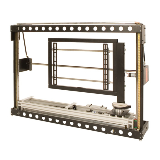
- Page 1 Plasma Lift Hinge Mechanism ISSUE: 006 Instruction Sheet www.futureautomation.co.uk FUTURE AUTOMATION...
- Page 2 Sheet 1 of 17 Plasma Lift Hinge Mechanism ISSUE: 006 1 IR Instruction Sheet www.futureautomation.co.uk Remote Control Your Pack Should Contain 1 PLH - Plasma Lift Hinge Mechanism Suitable for 26" to 50" screens 1 Standard PL Fixtures Pack The contents...
- Page 3 See SHEET 11 for further controls However, on some models there may be more than 6 cable ties. Once all the cable ties have been removed, then the mechanism can be powered up and tested. FUTURE AUTOMATION...
- Page 4 Fitting Flap And Base To Mechanism The 6mm flap and the base should be Consult made as part of the cabinet. PLH TECHNICAL SHEET The hole is necessary for hinge pole to pass through. before fabricating any The surface of the flap should be flaps or base panels.
- Page 5 3, shown below right. With the lift fixed in position, use 8 wood screws on each side to secure the lift to the cabinet. DETAIL B SCALE 2 : 3 FUTURE AUTOMATION...
- Page 6 Plasma Lift Hinge Mechanism ISSUE: 006 SCALE 1 : 1 Instruction Sheet www.futureautomation.co.uk Stage 4 Adjusting Base Panel Height By adjusting the screw up and down, you can adjust the stop height of the beam, and also the base panel. FUTURE AUTOMATION...
- Page 7 Positioning The Base Panel the plasma screen. SCALE 1 : 3 There should be a gap of about 3mm around the edges of the base panel to the cabinet. See Stage 2 for instructions on fixing the base. FUTURE AUTOMATION...
- Page 8 Be sure to lock the nut securely once adjusted. Make sure the black plate does not touch the inside of the cabinet. This can cause strain on the motor, leading to failure. FUTURE AUTOMATION...
- Page 9 By adjusting the bolts under each flap arm as circled, it is possible to alter the angle the flap opens to. It is very important that when the flap is open, it rests in a vertical position, as shown above. FUTURE AUTOMATION...
- Page 10 Place screen down carefully onto a flat surface, remove uprights from the mount and bolt onto the back of the screen. Carefully hook the screen with the uprights properly secured back onto the mounting frame and position. FUTURE AUTOMATION...
- Page 11 It may then be nessary to re-adjust the height of the lifting beam, as first dicussed in Stage 4 of these instructions. FUTURE AUTOMATION...
-
Page 12: Remote Controls
REMOTE ISSUE: 006 Instruction Sheet CONTROLS www.futureautomation.co.uk Stage 10 Takes the screen inside the cabinet. PLH mechanisms are all factory set to rotate 45 Takes the screen out of the cabinet and rotates 90 STOP Stops mechanism at any time... - Page 13 ( see sheet 14) can be stopped and a position can be stored in the memory so when the PRESET button is pushed the screen will go to that position. PRESS Rotates STORE To store a position in the memory FUTURE AUTOMATION...
-
Page 14: Electrical Connections
Plasma Lift Hinge Mechanism ISSUE: 006 Instruction Sheet www.futureautomation.co.uk Electrical Connections The PLH mechanism must be connected to the AC1, AC2, DC1 and DC2 blocks of connections. Remove this screw to release the lid Connect the Infrared Sensor here DETAIL A SCALE 1.2 : 1... -
Page 15: Contact Closure
When shorted to ground, DEVICE STOP stops device in current position. Momentary short to ground W/BR W/BR DEVICE OUT will make screen go UP but NOT HINGE. Momentary short to ground DEVICE IN will make device go IN. FUTURE AUTOMATION... - Page 16 = Device UP and to MEMORY fa left, = Device UP and to the LEFT PIN 1: IN fa right, = Device UP and to the Right PIN 6: OUT PIN 2: IN PIN 3&4: GROUND PIN 3: OUT PIN 5: GROUND FUTURE AUTOMATION...
-
Page 17: Operation Details
LED will also be on. Gives an ouput to control the Plasma Hinge motor. Gives an ouput of 240V(or 110V) to control the Plasma Lift motor. Outputs stay live for 60 seconds after FUTURE AUTOMATION the OUT or IN functions are selected. - Page 18 M8 x 30mm x4 Spacers 18 OD 8 ID 45mm x4 M8 x 60mm x6 Spacers 20 OD 6 ID 3mm M8 x 50mm x4 Spacers 20 OD 6 ID 3mm x8 M8 x 60mm x4 M8 x 80mm x4 FUTURE AUTOMATION...
Need help?
Do you have a question about the PLH and is the answer not in the manual?
Questions and answers