Table of Contents
Advertisement
Available languages
Available languages
Quick Links
Helios Ventilatoren
MONTAGE- UND BETRIEBSVORSCHRIFT
INSTALLATION AND OPERATING INSTRUCTIONS
NOTICE D'INSTALLATION ET D'UTILISATION
Zentral-Lüftungsgeräte
Central ventilation units
KWL EC 800 S Pro / WW
KWL EC 1200 S Pro / WW
KWL EC 1800 S Pro / WW
KWL EC 2600 S Pro / WW
Mit Wärmerückgewinnung und EC-Technik für
Be- und Entlüftung
With heat recovery and EC technology for ventilation
Ventilation double flux avec récupération de chaleur
et moteurs EC
DE
EN
FR
Advertisement
Chapters
Table of Contents

Related Manuals for Helios EC green Vent KWL EC 800 S Pro


Summary of Contents for Helios EC green Vent KWL EC 800 S Pro
- Page 1 Helios Ventilatoren MONTAGE- UND BETRIEBSVORSCHRIFT INSTALLATION AND OPERATING INSTRUCTIONS NOTICE D’INSTALLATION ET D’UTILISATION Zentral-Lüftungsgeräte Central ventilation units KWL EC 800 S Pro / WW KWL EC 1200 S Pro / WW KWL EC 1800 S Pro / WW KWL EC 2600 S Pro / WW Mit Wärmerückgewinnung und EC-Technik für...
- Page 2 DEUTSCH Dieses Produkt enthält Batterien bzw. Akkus: Batterien und Akkus dürfen nicht im Hausmüll entsorgt werden. Sie sind zur Rückgabe gebrauchter Batterien und Akkus gesetzlich verpflichtet. Sie können Batterien und Akkus im Handel oder in kommunalen Sammelstellen unentgeltlich zurückgeben. Batterien oder Akkus, die Schadstoffe enthalten, sind mit dem Symbol einer durchgekreuzten Mülltonne gekennzeichnet. Unter dem Mülltonnen-Symbol befindet sich die chemische Bezeichnung des Schadstoffes.
-
Page 3: Table Of Contents
Montage- und Betriebsvorschrift Zentral-Lüftungsgeräte KWL EC.. S Pro/WW Inhaltsverzeichnis KAPITEL 1 ALLGEMEINE MONTAGE- UND BETRIEBSHINWEISE ........Seite 2 Wichtige Informationen . -
Page 4: Wichtige Informationen
Wenn die nachfolgenden Ausführungen nicht beachtet werden, entfällt unsere Gewährleistung. Gleiches gilt für Haf- tungsansprüche an den Hersteller. Der Gebrauch von Zubehörteilen, die nicht von Helios empfohlen oder angeboten werden, ist nicht statthaft. Even tuell auftretende Schäden unterliegen nicht der Gewährleistung. -
Page 5: Funktion Und Wirkungsweise
Richtlinienreihe VDI 6022 „Raumlufttechnik, Raumluftqualität” und besitzen die entsprechende Zertifizierung. Die Richt- linien reichen von Betriebs- und Material- bis hin zu Konstruktionsvorschriften, welche eine hohe Luftqualität sicherstel- len. Für den VDI 6022 konformen Betrieb ist darauf zu achten, dass nur Helios Originalzubehör verwendet wird. 1.11 Feuerstätten Die einschlägig geltenden Vorschriften für den gemeinsamen Betrieb von Feuerstätte, Wohnungslüftung,... -
Page 6: Technische Daten
Montage- und Betriebsvorschrift Zentral-Lüftungsgeräte KWL EC.. S Pro/WW 1.12 Technische Daten KWL EC 800 S Pro Spannung/Frequenz 230 V~/50 Hz Anschluss nach Schaltplan SS-1370 Nennstrom – Lüftungsbetrieb Zulässige Lufttemperaturen -20 °C bis 40 °C Nennstrom – Vorheizung Gewicht 11,0 A 172 kg Max. - Page 7 Montage- und Betriebsvorschrift Zentral-Lüftungsgeräte KWL EC.. S Pro/WW KWL EC 2600 S Pro Spannung/Frequenz 3N 400 V~/50 Hz Anschluss nach Schaltplan SS-1370 Nennstrom – Lüftungsbetrieb Zulässige Lufttemperaturen 2,3/2,3/2,3 A -20 °C bis 40 °C Nennstrom – Vorheizung Gewicht 10,05/10,05/10,05 A 490 kg Max.
-
Page 8: Aufstellung
Montage- und Betriebsvorschrift Zentral-Lüftungsgeräte KWL EC.. S Pro/WW Aufstellung KAPITEL 2 Die Zentral-Lüftungsgeräte KWL EC.. S Pro/WW sind stehend zu montieren. Aufgrund von Betriebsgeräuschen, die sich je nach Anlagendruck verändern, wird empfohlen das KWL EC-Gerät im Waschraum, Technikräumen oder Lager- MONTAGE räumen aufzustellen. -
Page 9: Kondensatablauf
Gerätetype Maße KWL EC 800 S Pro ... KWL EC 1200 S Pro ... KWL EC 1800 S Pro ... KWL EC 2600 S Pro ... Im Helios-Zubehör sind Übergangsstücke Kanal auf Rohr erhältlich: Abb.7 Abb.8 Abb.9 Abb.10 ø 10 ø... -
Page 10: Luftführung, Lüftungsleitung
Montage- und Betriebsvorschrift Zentral-Lüftungsgeräte KWL EC.. S Pro/WW Luftführung, Lüftungsleitung Bei Planung und Ausführung sind möglichst kurze Leitungen anzustreben. Auf dichte Verbindungen und Übergänge ist zu achten. Zur Vermeidung von Schmutzablagerung, Druckverlust und Geräusch sind glattwandige Rohre (Kunststoff- oder Spiralfalzrohr) zu verwenden. Für Hauptleitungen (Außen-, Fortluft, Zuluftverteiler, Abluftsammler) ist DN: KWL EC 800 S.. -
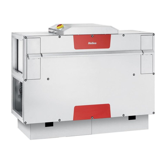
Page 11: Geräteübersicht
Montage- und Betriebsvorschrift Zentral-Lüftungsgeräte KWL EC.. S Pro/WW Geräteübersicht KAPITEL 3 WT-Befestigungsschienen Revisionsschalter (nicht sichtbar) FUNKTIONS- BESCHREIBUNG Klemmenkasten Elektr. Vorheizung Abluftluftfilter Automatischer Bypass ePM 10 50 % (M5) Außenluftfilter ePM 1 55 % (F7) Gehäuse EC-Hochleistungs- Frostschutz-Fühler WT ventilator – Zuluft EC-Hochleistungs- Warmwasser-Heizregister ventilator –... -
Page 12: Funktionen
Montage- und Betriebsvorschrift Zentral-Lüftungsgeräte KWL EC.. S Pro/WW Funktionen 3.2.1 Interne Vorheizung Nach Passivhauskriterien ist eine Vorheizung zwingend vorgeschrieben, um eine Vereisung des Kreuzgegenstrom- Wärmetauschers zu vermeiden! Die Vorheizung ist hinter dem Außenluftfilter platziert. Die Regelung ist nur aktiv um ein Vereisen des Geräts zu verhindern. WICHTIGER HINWEIS Wichtiger Hinweis: Die Aktivierung der Vorheizung erfolgt nur, wenn der Zuluftventilator den Mindestvolumenstrom fördert und kein Fehler... -
Page 13: Frostschutz Warmwasser-Heizregister
Montage- und Betriebsvorschrift Zentral-Lüftungsgeräte KWL EC.. S Pro/WW – Anschluss und Regelung des externen Warmwasser-Nachheizregisters (nur Type KWL EC.. S Pro) KWL EC .. Pro Bei den Gerätetypen KWL EC 800S/1800S/2600S Pro ist es möglich ein externes Warmwasser-Nachheizregister ein- zubinden (Abb.10). Die Regelung des Heizregisters kann dabei durch die Regelung des Lüftungsgerätes mittels Bedie- nelement erfolgen. -
Page 14: Notfall-Kontakt
Montage- und Betriebsvorschrift Zentral-Lüftungsgeräte KWL EC.. S Pro/WW 3.2.9 Notfall-Kontakt Die Funktion bei Öffnen des Notfall-Kontaktes ist im Servicemenü 13-Notfallluftstrom einstellbar. Im Drop-Down-Menü kann der Betriebsmodus bei geöffnetem Feuerkontakt (Platine A1, Klemme 15-16) ausgewählt werden: -keine Strömung -Strömung Zuluft + Abluft -Strömung nur Zuluft -Strömung nur Abluft Mit dem Schieberegler „Fließen“... -
Page 15: Und Feuchte-Sensor
Montage- und Betriebsvorschrift Zentral-Lüftungsgeräte KWL EC.. S Pro/WW – Wann wird der Gerätebypass genutzt? Der Bypass wird vorwiegend in den Sommermonaten zur sogenannten „Nachtkühlung“ genutzt. Bei der Nachtkühlung wird der Effekt der kühlen Außentemperaturen im Vergleich zu den Raum- bzw. Innentemperaturen genutzt. Der Bypass kann auch in den Übergangszeiten (Frühjahr und Herbst) genutzt werden, wenn meist aufgrund hoher Glas- flächen die Raumtemperatur tagsüber deutlicher höher ist als die Außenlufttemperatur („natürliche Bypasskühlung“). - Page 16 Montage- und Betriebsvorschrift Zentral-Lüftungsgeräte KWL EC.. S Pro/WW Aufputz-Komfortbedienelement mit Touchscreen KAPITEL 4 Um das Gerät in Betrieb zu nehmen, den Hauptschalter in die Position I (EIN) drehen. Wenn der Hauptschalter einge- schaltet ist, leuchtet das Display des Steuergeräts. BEDIENELEMENT Gerät einschalten â...
- Page 17 Montage- und Betriebsvorschrift Zentral-Lüftungsgeräte KWL EC.. S Pro/WW Zeitplan Zeitplan aktivieren/deaktivieren Start Zeitintervall Ende Zei- tintervall Zeitplan Wochen- Einschalten modus Einstellung Wochenmodus manueller oder automatischer utomat Jahresmodus Modus Jahres- zurück modus Zeitintervall löschen Zusätzlich zur Temperatur kann der Volumenstrom im manuellen Mo- dus eingestellt werden.
- Page 18 Montage- und Betriebsvorschrift Zentral-Lüftungsgeräte KWL EC.. S Pro/WW Zeit und Datum Belüftung Zeit & Datum entsprechend den Anforde- Manueller rungen des Lüftungs- Luftqualitäts- sensors betrieb DCV: Das Gerät lüftet entprechend den Anforderungen des Luftqualität- ssensors, z.B. CO , RH (0-10 V Steuersignal). CAV: Das Gerät lüftet entsprechend dem ausgewählten Volumenstrom und Service-Menü...
- Page 19 Montage- und Betriebsvorschrift Zentral-Lüftungsgeräte KWL EC.. S Pro/WW Menü 07 – Heizregister Menü 04 – Ventilatorenkalibrierung 01 - Modus 04 - Ventilatorenkalibrier 02 - Hw-Einstellung 05 - Filterkalibrierung Ventilatorenkalibrier Heizregister 05 - Filterkalibrierung 08 - AQS Sensor 07 - Heizregister 09 - Temperatursensor Ventilatorenkalibrierung...
- Page 20 Montage- und Betriebsvorschrift Zentral-Lüftungsgeräte KWL EC.. S Pro/WW Menü 09 – Temperatursensor Menü 11 – Bypasstemperatur 09 - 07 - Temperatursensor Heizregister 10 - 08 - Zuluftkanalgrenzwer AQS Sensor Bypasstemperatur Temperatursensor 12 - 10 - Luftstromabweichun Zuluftkanalgrenzwer 13 - 11 - Bypasstemperatur Notfallluftstrom Temperatursensor...
- Page 21 Montage- und Betriebsvorschrift Zentral-Lüftungsgeräte KWL EC.. S Pro/WW Menü 13 – Notfallluftstrom Menü 16 – Freecooling 13 - 14 - Occupancy Notfallluftstrom 11 - 10 - Meze foukání Bypasstemperatur 15 - 15 - Boost Boost 12 - 12 - Posun toků Luftstromabweichun 16 - Freecooling Freecooling...
- Page 22 Montage- und Betriebsvorschrift Zentral-Lüftungsgeräte KWL EC.. S Pro/WW Menü 18 – HW-Test 16 - 16 - Freecooling Freecooling 17 - PID-Param. 17 - PID Params 18 - HW test HW-Test 20 - Modbus RTU 20 - Modbus RTU 21 - Network 21 - Netzwerk Über das Menü...
- Page 23 Montage- und Betriebsvorschrift Zentral-Lüftungsgeräte KWL EC.. S Pro/WW Menü 50 – Zurück auf Werkseinstellung Benutzersicherung Schutzstufe Ohne PIN wechseln 23 - 23 - User lock Benutzersicherung 21 - Network 49 - Andere Einstellungen 49 - Other setting Benutzer- 23 - User lock sicherheits- Zurück auf Werkseins 50 -...
-
Page 24: Abmessungen
Montage- und Betriebsvorschrift Zentral-Lüftungsgeräte KWL EC.. S Pro/WW Abmessungen KAPITEL 5 KWL EC 800 S ABMESSUNGEN KENNLINIEN 1442 Abluft Außenluft Zuluft Fortluft Kondensat- ablauf Anschluss ø11 G 1 1/2" WW-Register G 1/2" Innengewinde KWL EC 1200 S 1705 Abluft Außenluft Zuluft Fortluft Kondensat-... -
Page 25: Einregulierung
Montage- und Betriebsvorschrift Zentral-Lüftungsgeräte KWL EC.. S Pro/WW KWL EC 2600 S 2195 Abluft Außenluft Zuluft Fortluft Kondensat- ablauf Anschluss G 1 1/2" WW-Register G 1/2" ø11 Innengewinde Einregulierung Einstellung der Volumenstrom-Kennlinien je Type mit Angabe zum empfohlenen Lüftungsbereich: KWL EC 1200 S Pro/WW KWL EC 800 S Pro/WW V ·... -
Page 26: Mindestanforderungen Zur Inbetriebnahme
Montage- und Betriebsvorschrift Zentral-Lüftungsgeräte KWL EC.. S Pro/WW 5.2. Mindestanforderungen zur Inbetriebnahme Die Inbetriebnahme erfolgt über eine Anlagenkalibrierung. Hierzu wird im Bedienelement Komfort das Servicemenü 04-Ventilatoren-Kalibrierung aktiviert und die Anlage fährt die Anlagenkennlinie ab. Die Kalibrierung dauert ca. 3-5 Minuten! Bei ungewöhnlichen Anlagedrücken, muss die Installation überprüft werden! Eventuell sind hierfür Fremd- WICHTIG körper oder eine unsachgemäße Installation verantwortlich. -
Page 27: Filterwechsel
Montage- und Betriebsvorschrift Zentral-Lüftungsgeräte KWL EC.. S Pro/WW 4. Wärmetauscherarretierungen lösen. Hierbei die sechs Arretierungsschienen nach vorne ziehen (Abb.17) 5. Kreuzgegenstrom-Wärmetauscher vorsichtig aus dem Gerät ziehen und gesichert absetzen (Abb.18) VERLETZUNGSGEFAHR! Hohes Gewicht! Demontage muss mit zwei Personen erfolgen! WARNUNG Abb.17 Abb.18 Zur Reinigung den Wärmetauscher vorsichtig mit einem Hochdruckreiniger reinigen. -
Page 28: Reset-Funktion Des Heizregisters
Montage- und Betriebsvorschrift Zentral-Lüftungsgeräte KWL EC.. S Pro/WW – Filter Das KWL-Kompaktgerät ist serienmäßig außen- und abluftseitig mit Feinfiltern ausgestattet (nach DIN EN 13779). Die geräteinterne druckabhängige Filterüberwachung signalisiert auf dem Bedienteil die Notwendigkeit der Kontrolle und Reinigung bzw. Austausch der Filter. Unabhängig davon wird eine 3-monatige Kontrolle empfohlen. Spätestens nach 1-jährigem Betrieb müssen die Filter aus hygienischen Gründen ausgetauscht werden. -
Page 29: Demontage Des Elektrischen Heizregisters
Montage- und Betriebsvorschrift Zentral-Lüftungsgeräte KWL EC.. S Pro/WW Demontage des elektrischen Heizregisters 1. Kreuzgegenstrom-Wärmetauscher demontieren wie in Punkt 6.1 beschrieben 2. Kabelverbindungen trennen (Abb.27) 3. Befestigungsschrauben des Heizregisters herausdrehen (Abb.28/29). Abb.27 Abb.28 4. Elektrisches Heizregister entnehmen (Abb.30) WARNUNG m SCHNITTGEFAHR! Scharfe Kanten! Abb.29 Abb.30 Kondensatablauf im Gerät... -
Page 30: Problembehandlung
Montage- und Betriebsvorschrift Lüftungsgeräte KWL EC 800 S/1200 S/1800 S/2600 S Pro/WW Problembehandlung Fehler Geräteverhalten Problem Lösung 4 - Fehler des Zuluftventi- Gerät funktioniert nicht Überhitzung des Ventilators Ursache für das Überhitzen des Ventilators feststellen (fehler- lators oder eine Beschädigung an haftes Lager, mechanisches Problem, Kurzschluss,...). - Page 31 Montage- und Betriebsvorschrift Lüftungsgeräte KWL EC 800 S/1200 S/1800 S/2600 S Pro/WW Fehler Geräteverhalten Problem Lösung 26 - Fehler am Drucksensor Gerät lüftet Fehler am Drucksensor Kontrollieren ob die Messeinrichtung beschädigt oder des Abluftfilters verschmutzt ist. Prüfung der Druckschläuche auf Durchgän- gigkeit.
-
Page 32: Verdrahtungsplan Kwl Ec 800 S
Montage- und Betriebsvorschrift Zentral-Lüftungsgeräte KWL EC.. S Pro/WW Verdrahtungsplan 85 499 157 (KWL EC 800 S) KAPITEL 7 Abb.31 SCHALTPLANÜBERSICHT... - Page 33 Montage- und Betriebsvorschrift Zentral-Lüftungsgeräte KWL EC.. S Pro/WW Verdrahtungsplan 85 499 158 (KWL EC 1200 S) Abb.33...
- Page 34 Montage- und Betriebsvorschrift Zentral-Lüftungsgeräte KWL EC.. S Pro/WW Verdrahtungsplan 85 499 159 (KWL EC 1800 S) Abb.32...
- Page 35 Montage- und Betriebsvorschrift Zentral-Lüftungsgeräte KWL EC.. S Pro/WW Verdrahtungsplan 85 499 160 (KWL EC 2600 S) Abb.33...
- Page 36 Montage- und Betriebsvorschrift Zentral-Lüftungsgeräte KWL EC.. S Pro/WW Anschlussplan SS-1370 (KWL EC.. S Pro/WW) Abb.34...
-
Page 37: Konformitätserklärung
Montage- und Betriebsvorschrift Zentral-Lüftungsgeräte KWL EC.. S Pro/WW KAPITEL 8 KONFORMITÄTS- ERKLÄRUNG... - Page 38 ENGLISH This product contains batteries or accumulators: Batteries and accumulators must not be disposed of in household waste. You are legally obligated to return used batteries and accumulators. You can return batte- ries to a community collection point or return them to the place where you bought them free of charge. Batteries or accumulators that contain harmful substances are labelled with the symbol of a crossed-out waste bin.
- Page 39 Installation and Operating Instructions Central Ventilation Units KWL EC.. S Pro/WW Table of Contents CHAPTER 1 GENERAL INSTALLATION AND OPERATING INSTRUCTIONS ......Page 2 Important information .
-
Page 40: Chapter 1 General Installation And Operating Instructions
If the preceding instructions are not observed, all warranty claims and accommodation treatment are excluded. This also applies to any liability claims extended to the manufacturer. The use of accessories not offered or recommended by Helios is not permitted. Potential damages are not covered by warranty. -
Page 41: Function And Mode Of Operation
1.10 Guideline series VDI 6022 The Helios KWL central ventilation units in this series comply with VDI 6022. They fulfil the hygiene requirements in the guideline series VDI 6022 “Ventilation technology, indoor-air quality” and they have been certified accordingly. The gui- delines range from operating instructions and material regulations through to construction rules, which ensure high air quality. -
Page 42: Technical Data
Installation and Operating Instructions Central Ventilation Units KWL EC.. S Pro/WW 1.12 Technical data KWL EC 800 S Pro Voltage/Frequency 230 V~/50 Hz Wiring diagram SS-1370 Rated current – ventilation Permissible air temperatures -20 °C to 40 °C Rated current – pre-heater Weight 11.0 A 172 kg... - Page 43 Installation and Operating Instructions Central Ventilation Units KWL EC.. S Pro/WW KWL EC 2600 S Pro Voltage/Frequency 3N 400 V~/50 Hz Wiring diagram SS-1370 Rated current – ventilation Permissible air temperatures 2.3/2.3/2.3 A -20 °C to 40 °C Rated current – pre-heater Weight 10.05/10.05/10.05 A 490 kg...
-
Page 44: Chapter 2 Installation
Installation and Operating Instructions Central Ventilation Units KWL EC.. S Pro/WW Assembly CHAPTER 2 The central ventilation units KWL EC.. S Pro/WW must be mounted in a vertical position. Due to operating noises which change according to system pressure, it is recommended to install the KWL unit in the washing room, utility rooms or INSTALLATION storerooms. -
Page 45: Condensation Outlet
Dim. KWL EC 800 S Pro ... KWL EC 1200 S Pro ... KWL EC 1800 S Pro ... KWL EC 2600 S Pro ... Duct-to-pipe connecting pieces are available in the Helios range: Fig.7 Fig.8 Fig.9 Fig.10 ø 10 ø... -
Page 46: Air Ducting, Ventilation Circuit
Installation and Operating Instructions Central Ventilation Units KWL EC.. S Pro/WW Air ducting, Ventilation circuit When designing the ductwork, use the shortest possible runs. Airtight connections and changeovers must be ensured for the best possible heat recovery. To avoid pressure losses, dirt build-up and noise, use smooth ducts (plastic or rigid ducting). -
Page 47: Chapter 3 Functional Description
Installation and Operating Instructions Central Ventilation Units KWL EC.. S Pro/WW Unit overview CHAPTER 3 WT mounting rails Isolator switch (not visible) FUNCTIONAL DESCRIPTION Terminal box Elec. pre-heater Extract air filter Automatic bypass ePM 10 50 % (M5) Outside air filter ePM 1 55 % (F7) Housing EC-high performance... -
Page 48: Functions
Installation and Operating Instructions Central Ventilation Units KWL EC.. S Pro/WW Functions 3.2.1 Internal pre-heater According to criteria for passive houses, a pre-heater is mandatory to prevent the cross-counter flow heat exchanger from freezing! The pre-heater is located behind the outside air filter. The pre-heater is active to prevent the unit from icing up. -
Page 49: Frost-Protection Hot Water Heater Battery
Installation and Operating Instructions Central Ventilation Units KWL EC.. S Pro/WW – Connection and regulation of external hot water auxiliary heater battery (only type KWL EC.. S Pro) KWL EC .. Pro It is possible to integrate an external hot water aux. heater on unit types KWL EC 800S/1800S/2600S Pro (Fig. 10). The heater battery can be regulated with the controller by regulating the ventilation unit. -
Page 50: Emergency Contact
Installation and Operating Instructions Central Ventilation Units KWL EC.. S Pro/WW 3.2.9 Emergency contact The function when the emergency contact is open can be set in service menu 13 emergency air flow. The operating mode when the fire contact (circuit board A1, terminal 15-16) is open can be selected in the drop-down menu: -No flow -Flow supply air + extract air... -
Page 51: Demand-Driven Regulation Of Ventilation Units Through Co
Installation and Operating Instructions Central Ventilation Units KWL EC.. S Pro/WW – When is the unit bypass used? The bypass is normally used in the summer months for so-called “night cooling“. With regard to night cooling. the effect of cool outside temperatures is used in comparison to room or inside temperatures. The bypass can also be used in transition periods (spring and autumn) if the room temperature is significantly higher than the outside air temperature during the day due to high windows (“natural bypass cooling“). -
Page 52: Chapter 4 Controller
Installation and Operating Instructions Central Ventilation Units KWL EC.. S Pro/WW Surface-mounted controller with touch screen CHAPTER 4 In order to operate the unit, turn the main switch to position I (ON). When the main switch is turned on, the controller display lights up. - Page 53 Installation and Operating Instructions Central Ventilation Units KWL EC.. S Pro/WW Schedule Activate/deactivate schedule Start interval End of interval Zeitplan Weekly Einschalten mode Set manual or Wochenmodus automatic mode utomat Jahresmodus Yearly mode Back Delete interval In addition to the temperature, the flow rate can be set in manual mode. After the interval, the unit will switch to the previous mode.
- Page 54 Installation and Operating Instructions Central Ventilation Units KWL EC.. S Pro/WW Time and date Ventilation Time & date according to the require- Manual ments of the ventilation air quality sensor mode DCV: The unit ventilates according to the requirements of the air quality sen- sor, e.g.
- Page 55 Installation and Operating Instructions Central Ventilation Units KWL EC.. S Pro/WW Menu 07 – Heater battery Menu 04 – Fan calibration 01 - Modus 04 - Ventilatorenkalibrier 02 - Hw-Einstellung 05 - Filterkalibrierung Ventilatorenkalibrier Heizregister 05 - Filterkalibrierung 08 - AQS Sensor 07 - Heizregister...
- Page 56 Installation and Operating Instructions Central Ventilation Units KWL EC.. S Pro/WW Menu 09 – Temperature sensor Menu 11 – Bypass temperature 07 - Heizregister 08 - AQS Sensor Bypasstemperatur Temperatursensor 12 - 10 - Luftstromabweichun Zuluftkanalgrenzwer 13 - 11 - Bypasstemperatur Notfallluftstrom Temperature probe...
- Page 57 Installation and Operating Instructions Central Ventilation Units KWL EC.. S Pro/WW Menu 13 – Emergency airflow Menu 16 – Free cooling 13 - 14 - Occupancy Notfallluftstrom 14 - Occupancy 10 - Meze foukání 11 - 10 - Meze foukání Bypasstemperatur 15 - 15 - Boost...
- Page 58 Installation and Operating Instructions Central Ventilation Units KWL EC.. S Pro/WW Menu 18 – HW test 16 - 16 - Freecooling Free cooling 17 - PID-Param. 17 - PID Params 18 - HW test HW test 20 - Modbus RTU 20 - Modbus RTU 21 - Network...
- Page 59 Installation and Operating Instructions Central Ventilation Units KWL EC.. S Pro/WW Menu 50 – Factory reset User lock Protection level None Change PIN 23 - 23 - User lock User lock 21 - Network 49 - Other settings 49 - Other setting User securi- 23 - User lock ty level...
-
Page 60: Chapter 5 Dimensions / Characteristic Curves
Installation and Operating Instructions Central Ventilation Units KWL EC.. S Pro/WW Dimensions CHAPTER 5 KWL EC 800 S DIMENSIONS CHARACTERISTIC CURVES 1442 Abluft Außenluft Extract air Outside air Zuluft Fortluft Supply air Exhaust air Kondensat- ablauf Anschluss Connection Condensation drain WW heater battery G 1/2“... -
Page 61: Adjustment
Installation and Operating Instructions Central Ventilation Units KWL EC.. S Pro/WW KWL EC 2600 S 2195 Abluft Extract air Außenluft Outside air Supply air Zuluft Fortluft Exhaust air Kondensat- ablauf Anschluss Connection Condensation drain WW heater battery G 1/2“ G 1 1/2" WW-Register G 1/2"... -
Page 62: Minimum Requirements For Commissioning
Installation and Operating Instructions Central Ventilation Units KWL EC.. S Pro/WW 5.2. Minimum requirements for commissioning The commissioning is carried out through a system calibration. In this respect, “Fan-calibration“ (see also Page 20) is activated on the controller > Service menu 04: and the system starts the system characteristic curve. The calibration takes around 3-5 minutes! In case of unusual system pressures, the installation must be checked! Foreign bodies or incorrect installation IMPORTANT... -
Page 63: Filter Change
Installation and Operating Instructions Central Ventilation Units KWL EC.. S Pro/WW 4. Loosen the heat exchanger locks. In this respect, pull the six locking tracks forward (Fig.17) 5. Carefully pull cross counter flow heat exchanger from the unit and set down carefully (Fig.18) RISK OF INJURY! High weight! Two persons are required for dismantling! WARNING Fig.17... -
Page 64: Heater Battery Reset Function
Installation and Operating Instructions Central Ventilation Units KWL EC.. S Pro/WW – Filter The KWL compact unit is equipped with fine filters on the outside and extract air side as standard (DIN EN 13779). The internal pressure-dependent filter monitoring system signals the necessity of inspection and cleaning or filter replacement on the controller. -
Page 65: Removal Of The Electric Heater Battery
Installation and Operating Instructions Central Ventilation Units KWL EC.. S Pro/WW Removal of the electric heater battery 1. Dismantle the cross-flow heat exchanger as described in section 6.1 2. Disconnect the cable connections (Fig.27) 3. Loosen the fixing screws of the heater battery (Fig.28/29). Fig.27 Fig.28 4. -
Page 66: Troubleshooting
Installation and Operating Instructions Central Ventilation Units KWL EC 800 S/1200 S/1800 S/2600 S Pro/WW Troubleshooting Fault Unit behaviour Problem Solution 4 - Supply air fan fault Unit does not operate Fan overheating or damage Determine cause of fan overheating (faulty bearing, mechani- to the thermal contacts of cal problem, short circuit,...). - Page 67 Installation and Operating Instructions Central Ventilation Units KWL EC 800 S/1200 S/1800 S/2600 S Pro/WW Fault Unit behaviour Problem Solution 27 - Fault with pressure Unit ventilates Pressure sensor fault Check whether the measuring device is damaged or sensor of supply air filter contaminated.
-
Page 68: Chapter 7 Wiring Diagram Overview
Installation and Operating Instructions Central Ventilation Units KWL EC.. S Pro/WW Wiring diagram 85 499 157 (KWL EC 800 S) CHAPTER 7 Fig.31 WIRING DIAGRAM OVERVIEW... - Page 69 Installation and Operating Instructions Central Ventilation Units KWL EC.. S Pro/WW Wiring diagram 85 499 158 (KWL EC 1200 S) Fig.33...
- Page 70 Installation and Operating Instructions Central Ventilation Units KWL EC.. S Pro/WW Wiring diagram 85 499 159 (KWL EC 1800 S) Fig.32...
- Page 71 Installation and Operating Instructions Central Ventilation Units KWL EC.. S Pro/WW Wiring diagram 85 499 160 (KWL EC 2600 S) Fig.33...
- Page 72 Installation and Operating Instructions Central Ventilation Units KWL EC.. S Pro/WW Wiring plan SS-1370 (KWL EC.. S Pro/WW) Fig.34...
-
Page 73: Chapter 8 Declaration Of Conformity
Installation and Operating Instructions Central Ventilation Units KWL EC.. S Pro/WW CHAPTER 8 DECLARATION OF CONFORMITY... - Page 74 FRANÇAIS Ce produit contient des batteries et des accus : Les batteries et les accus ne doivent pas être en jetés avec les ordures ménagères classiques. La législation impose la restitution d’accus et de batteries usagés. Vous pouvez les déposer gratuitement dans les endroits prévus à cet effet dans le commerce ou dans les points de collectes de votre commune. Les batteries ou les accus contenant des substances nocives ont le symbole ci-contre (poubelle barrée) dessus.
- Page 75 Notice d’installation et d’utilisation Centrales double flux KWL EC .. S Pro/WW Sommaire CHAPITRE 1 INFORMATIONS GÉNÉRALES CONCERNANT L’INSTALLATION ET L’UTILISATION ..Page 2 Informations importantes ............. . . Page 2 Précautions et consignes de sécurité...
-
Page 76: Informations Importantes
Si toutes les consignes indiquées dans cette notice ne sont pas correctement respectées, la garantie s’annule. Idem pour les réserves constructeur. L’utilisation d’accessoires non conseillés ou proposés par Helios n’est pas permise. Les dégâts causés par cette mauvaise utilisation ne sont pas inclus dans la garantie. -
Page 77: Fonctionnement
1.10 Normes VDI 6022 Les unités Helios KWL à récupération de chaleur de cette série sont conformes VDI 6022. Cela englobe les réglemen- tations d’hygiène de la série de normes VDI 6022 „aéraulique, qualité d’air” et répondent aux différentes certifications correspondantes. -
Page 78: Données Techniques
Notice d’installation et d’utilisation Centrales double flux KWL EC .. S Pro/WW 1.12 Données techniques KWL EC 800 S Pro Tension/Fréquence 230 V~/50 Hz Raccordement selon schéma SS-1370 Tension nominale – Ventilation Température air max. -20 °C à 40 °C Tension nominale –... - Page 79 Notice d’installation et d’utilisation Centrales double flux KWL EC .. S Pro/WW KWL EC 2600 S Pro Tension/Fréquence 3N 400 V~/50 Hz Raccordement selon schéma SS-1370 Tension nominale – Ventilation Température air max. 2,3/2,3/2,3 A -20 °C à 40 °C Tension nominale –...
-
Page 80: Mise En Place
Notice d’installation et d’utilisation Centrales double flux KWL EC .. S Pro/WW Mise en place CHAPITRE 2 La centrale double flux KWL EC ..S Pro / WW est conçue pour une installation verticale. En raison des niveaux sonores qui varient selon la pression de l’appareil, il est recommandé d’installer la centrale KWL EC dans un local technique. MONTAGE Veiller à... -
Page 81: Évacuation Des Condensats
KWL EC 800 S Pro ... KWL EC 1200 S Pro ... KWL EC 1800 S Pro ... KWL EC 2600 S Pro ... Helios propose dans ses accessoires des collerettes en gaine à positionner sur le tuyau : Fig. 7 Fig. 8 Fig. 9 Fig. -
Page 82: Réseaux Et Débits D'air
Notice d’installation et d’utilisation Centrales double flux KWL EC .. S Pro/WW Réseaux et débits d’air Privilégier des réseaux courts et choisir des raccords étanches. Afin d’éviter les accumulations de poussières, les pertes de pression et le bruit, utiliser des conduits lisses (tube plastique ou acier agrafé en spirale). Pour les réseaux principaux (air extérieur, air rejeté, air soufflé... -
Page 83: Schéma De L'appareil
Notice d’installation et d’utilisation Centrales double flux KWL EC .. S Pro/WW Aperçu de l’unité CHAPITRE 3 Rails de fixation - WT Interrupteur de révision (non visible) DESCRIPTION DES FONCTIONNALITÉS Boîte à bornes Batterie électrique Filtre air repris Bypass automatique ePM10 50 % (M5) Filtre air extérieur ePM1 55 % (F7) -
Page 84: Fonctions
Notice d’installation et d’utilisation Centrales double flux KWL EC .. S Pro/WW Fonctions 3.2.1 Préchauffage interne Selon les critères de conception d’une maison passive (PHI), un préchauffage est impératif pour éviter le givrage de l’échangeur de chaleur à contre-courant ! Le préchauffage est positionné derrière le filtre air extérieur F7. La régulation est uniquement active pour empêcher le givrage de l’appareil. -
Page 85: Protection Antigel De La Batterie À Eau Chaude
Notice d’installation et d’utilisation Centrales double flux KWL EC .. S Pro/WW – Raccordement et réglage de la batterie à eau chaude externe (uniquement types KWL EC ..S Pro) KWL EC .. Pro Sur les centrales types KWL EC 800/1800/2600S Pro, il est possible de raccorder une batterie à eau chaude externe (Fig. -
Page 86: Contact D'urgence
Notice d’installation et d’utilisation Centrales double flux KWL EC .. S Pro/WW 3.2.9 Contact d’urgence La fonction associée à l’ouverture du contact d’urgence peut être paramétrée dans le menu 13 fonctionnement en mode incendie. Dans le menu déroulant, le mode de fonctionnement peut être sélectionné avec le contact incendie ouvert (carte élec- tronique A1, bornes 15-16) : - pas de ventilation - soufflage + extraction... -
Page 87: Et D'hygrométrie
Notice d’installation et d’utilisation Centrales double flux KWL EC .. S Pro/WW – Quand le bypass de l’appareil est-il utilisé ? Le bypass est notamment utilisé durant la période estivale en vue du « refroidissement nocturne ». Le refroidissement nocturne utilise l’effet des températures extérieures qui sont fraîches par rapport aux températures ambiantes ou inté- rieures. -
Page 88: Commande À Distance Avec Écran Tactile
Notice d’installation et d’utilisation Centrales double flux KWL EC .. S Pro/WW Commande à distance avec écran tactile CHAPITRE 4 Pour faire fonctionner l’appareil, tourner l’interrupteur principal en position I (ON). Lorsque l’interrupteur principal est activé, l’affichage du contrôleur s’allume. COMMANDE À... - Page 89 Notice d’installation et d’utilisation Centrales double flux KWL EC .. S Pro/WW Programme Activer/désactiver programme Début de la période de programmation Fin de la période Zeitplan Mode Einschalten hebdomadaire Réglage du mode Wochenmodus manuel ou automatique utomat Jahresmodus Mode Supprimer Retour annuel la plage de...
- Page 90 Notice d’installation et d’utilisation Centrales double flux KWL EC .. S Pro/WW Heure et date Ventilation Zeit & Datum conforme aux exigences de Fonctionnement la sonde de qualité d’air de ventilation manuelle DCV :L’appareil ventile conformément aux exigences de la sonde de qualité d’air, par ex.
- Page 91 Notice d’installation et d’utilisation Centrales double flux KWL EC .. S Pro/WW Menu 07 – Batteries additionnelles Menu 04 – Étalonnage du ventilateur 01 - Modus 04 - Ventilatorenkalibrier 02 - Hw-Einstellung 05 - Filterkalibrierung Ventilatorenkalibrier Heizregister 05 - Filterkalibrierung 08 - AQS Sensor 07 -...
- Page 92 Notice d’installation et d’utilisation Centrales double flux KWL EC .. S Pro/WW Menu 09 – Sonde de température Menu 11 – Température Bypass 09 - 07 - Temperatursensor Heizregister 10 - 08 - Zuluftkanalgrenzwer AQS Sensor Bypasstemperatur Temperatursensor 12 - 10 - Luftstromabweichun Zuluftkanalgrenzwer...
-
Page 93: Réglage Du Débit D'air
Notice d’installation et d’utilisation Centrales double flux KWL EC .. S Pro/WW Menu 13 – Fonctionnement en mode incendie Menu 16 – Freecooling 13 - 14 - Occupancy Notfallluftstrom 11 - 10 - Meze foukání Bypasstemperatur 15 - 15 - Boost Boost 12 - 12 - Posun toků... - Page 94 Notice d’installation et d’utilisation Centrales double flux KWL EC .. S Pro/WW Menu 18 – Mode Test 16 - 16 - Freecooling Freecooling 17 - PID-Param. 17 - PID Params 18 - HW test HW-Test 20 - Modbus RTU 20 - Modbus RTU 21 - Network 21 -...
- Page 95 Notice d’installation et d’utilisation Centrales double flux KWL EC .. S Pro/WW Menu 50 – Réinitialiser les paramètres usine Benutzersicherung Schutzstufe Ohne PIN wechseln 23 - 23 - User lock Benutzersicherung 21 - Network 49 - Andere Einstellungen 49 - Other setting Étape de 23 - User lock sécurité...
- Page 96 Notice d’installation et d’utilisation Centrales double flux KWL EC .. S Pro/WW Dimensions CHAPITRE 5 DIMENSIONS KWL EC 800 S COURBES 1442 Abluft Außenluft air repris air extérieur Zuluft Fortluft air rejeté air soufflé Évacuation des Kondensat- condensats ablauf Anschluss Raccordement ø11 G 1 1/2"...
- Page 97 Notice d’installation et d’utilisation Centrales double flux KWL EC .. S Pro/WW KWL EC 2600 S 2195 Abluft air repris Außenluft air extérieur Zuluft air soufflé Fortluft air rejeté Évacuation des Kondensat- condensats ablauf Anschluss Raccordement G 1 1/2" WW-Register G 1/2" ø11 Batterie WW G 1/2“...
-
Page 98: Exigences Minimales Relatives À La Mise En Service
Notice d’installation et d’utilisation Centrales double flux KWL EC .. S Pro/WW 5.2. Exigences minimales relatives à la mise en service La mise en service se fait via un dimensionnement de l’installation. « Dimensionnement vent. » sera activé dans l’unité de commande au menu de service 04-Étalonnage du ventliteur et l’installation génère des courbes. - Page 99 Notice d’installation et d’utilisation Centrales double flux KWL EC .. S Pro/WW 4. Défaire les arêtes de l’échangeur. Tirer vers soi les 6 rails des arrêtes, en même temps (Fig. 17). 5. Tirer avec précaution l’échangeur à chaleur hors de l’unité et le déposer délicatement (Fig. 18). RISQUE DE BLESSURE ! Poids élevé...
-
Page 100: Fonction Reset (Batteries)
Notice d’installation et d’utilisation Centrales double flux KWL EC .. S Pro/WW – Filtres La centrale double flux KWL EC est équipée en série de filtres sur l’air extérieur et l’air repris (selon EN 13779) : • Air extérieur / repris : Filtre de rechange F5 air repris 1 pc. -
Page 101: Démontage De La Batterie Électrique
Notice d’installation et d’utilisation Centrales double flux KWL EC .. S Pro/WW Démontage de la batterie électrique 1. Démonter l’échangeur de chaleur à contre-courant comme indiqué dans la section 6.1. 2. Séparer les liaisons de câble (Fig. 27) 3. Dévisser les vis de fixation de la batterie électrique (Fig. 28/29). Fig. -
Page 102: Description Des Erreurs
Notice d’installation et d’utilisation Centrales double flux KWL EC .. S Pro/WW Description des erreurs Comportement de Erreur Problème Solution l’appareil 4 - Erreur du ventilateur du L’unité ne fonctionne pas. Surchauffe du ventilateur Cause de surchauffe du ventilateur (par exemple, roulement soufflage ou endommagement des défectueux, problème mécanique, court-circuit, ...). - Page 103 Notice d’installation et d’utilisation Centrales double flux KWL EC .. S Pro/WW Comportement de Erreur Problème Solution l’appareil 26 - Erreur sur la sonde de L’unité fonctionne. Erreur sur la sonde de Vérifier si l’appareil de mesure est endommagé ou sale. pression du filtre d’air extrait pression.
-
Page 104: Schéma De Câblage Ss-1238 (Kwl Ec 800 S)
Notice d’installation et d’utilisation Centrales double flux KWL EC .. S Pro/WW Schéma de câblage 85 499 157 (KWL EC 800 S) CHAPITRE 7 Fig. 31 SCHÉMA DE RACCORDEMENT... - Page 105 Notice d’installation et d’utilisation Centrales double flux KWL EC .. S Pro/WW Schéma de câblage 85 499 158 (KWL EC 1200 S) Fig. 33...
- Page 106 Notice d’installation et d’utilisation Centrales double flux KWL EC .. S Pro/WW Schéma de câblage 85 499 159 (KWL EC 1800 S) Fig. 32...
- Page 107 Notice d’installation et d’utilisation Centrales double flux KWL EC .. S Pro/WW Schéma de câblage 85 499 160 (KWL EC 2600 S) Fig. 33...
- Page 108 Notice d’installation et d’utilisation Centrales double flux KWL EC .. S Pro/WW Schéma de raccordement SS-1370 (KWL EC.. S Pro/WW) Fig. 34...
- Page 109 Notice d’installation et d’utilisation Centrales double flux KWL EC .. S Pro/WW CHAPITRE 8 DÉCLARATION DE CONFORMITÉ...
- Page 110 Notice d’installation et d’utilisation Centrales double flux KWL EC .. S Pro/WW...
- Page 111 Notice d’installation et d’utilisation Centrales double flux KWL EC .. S Pro/WW...
- Page 112 HELIOS Ventilatoren GmbH + Co KG · Lupfenstraße 8 · 78056 VS-Schwenningen HELIOS Ventilateurs · Le Carré des Aviateurs · 157 avenue Charles Floquet · 93155 Le Blanc Mesnil Cedex CH HELIOS Ventilatoren AG · Tannstrasse 4 · 8112 Otelfingen GB HELIOS Ventilation Systems Ltd.
Need help?
Do you have a question about the EC green Vent KWL EC 800 S Pro and is the answer not in the manual?
Questions and answers