KROHNE OPTIWAVE 1400 C Handbook
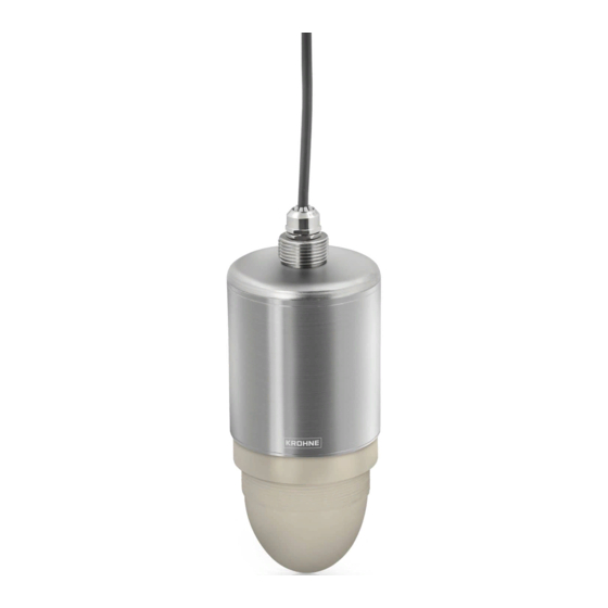
24 ghz radar (fmcw) level transmitter for liquids in the water and waste water industry
Hide thumbs
Also See for OPTIWAVE 1400 C:
- Supplementary instructions manual (16 pages) ,
- Supplementary instructions manual (16 pages)
Table of Contents
Advertisement
Quick Links
Advertisement
Table of Contents

Subscribe to Our Youtube Channel
Related Manuals for KROHNE OPTIWAVE 1400 C


Summary of Contents for KROHNE OPTIWAVE 1400 C
- Page 1 OPTIWAVE 1400 C OPTIWAVE 1400 C OPTIWAVE 1400 C OPTIWAVE 1400 C Handbook Handbook Handbook Handbook 24 GHz Radar (FMCW) Level Transmitter for liquids in the water and waste water industry © KROHNE 05/2019 - 4007046301 - MA OPTIWAVE1400 R01 en...
- Page 2 All rights reserved. It is prohibited to reproduce this documentation, or any part thereof, without the prior written authorisation of KROHNE Messtechnik GmbH. Subject to change without notice. Copyright 2019 by KROHNE Messtechnik GmbH - Ludwig-Krohne-Str. 5 - 47058 Duisburg (Germany) www.krohne.com 05/2019 - 4007046301 - MA OPTIWAVE1400 R01 en...
-
Page 3: Table Of Contents
CONTENTS OPTIWAVE 1400 C 1 Safety instructions 1.1 Software history ....................... 6 1.2 Intended use ........................6 1.3 Certification ........................7 1.4 Radio approvals ........................ 8 1.4.1 European Union (EU)....................... 8 1.4.2 U.S.A. and Canada......................... 10 1.5 Safety instructions from the manufacturer ..............13 1.5.1 Copyright and data protection .................... - Page 4 CONTENTS OPTIWAVE 1400 C 5 Start-up 5.1 Start-up checklist......................32 5.2 Operating concept ......................32 5.3 PACTware™: general notes ................... 32 5.4 PACTware: software installation..................32 5.5 How to start the device....................33 5.6 Software configuration ....................34 5.6.1 General notes........................34 5.6.2 Procedure..........................
- Page 5 CONTENTS OPTIWAVE 1400 C 8 Technical data 8.1 Measuring principle......................62 8.2 Technical data......................... 63 8.3 Measuring accuracy ....................... 67 8.4 Minimum power supply voltage ..................68 8.5 Dimensions and weights ....................69 9 Appendix 9.1 Function description....................... 77 9.2 Device status and error messages ................92 9.2.1 Error mapping (NAMUR NE 107) ..................
-
Page 6: Safety Instructions
SAFETY INSTRUCTIONS OPTIWAVE 1400 C 1.1 Software history "Firmware revision" agrees with NAMUR NE 53. It is a series of numbers used to record the revision status of embedded software (firmware) in electronic equipment assemblies. It gives data on the type of changes made and the effect that changes have on compatibility. -
Page 7: Certification
SAFETY INSTRUCTIONS OPTIWAVE 1400 C 1.3 Certification CE marking The device meets the essential requirements of the EU Directives: • Electromagnetic Compatibility (EMC) directive • The safety part of the Low-Voltage directive The manufacturer certifies successful testing of the product by applying the CE marking. For more data about the EU Directives and European Standards related to this device, refer to the EU Declaration of Conformity. -
Page 8: Radio Approvals
SAFETY INSTRUCTIONS OPTIWAVE 1400 C 1.4 Radio approvals 1.4.1 European Union (EU) INFORMATION! LPR (Level Probing Radar) LPR (Level Probing Radar) LPR (Level Probing Radar) LPR (Level Probing Radar) devices measure level in the open air or in a closed space (a metallic tank etc.). - Page 9 SAFETY INSTRUCTIONS OPTIWAVE 1400 C Radio quiet zones: locations of radio astronomy sites (stations) in Europe and northern Eurasia Country Name of the station Location Latitude, ϕ Longitude, λ Finland Metsähovi 60°13'04" N 24°23'37" E Tuorla 60°24'56" N 22°26'31" E...
-
Page 10: And Canada
SAFETY INSTRUCTIONS OPTIWAVE 1400 C 1.4.2 U.S.A. and Canada INFORMATION! LPR (Level Probing Radar) LPR (Level Probing Radar) devices measure level in the open air or in a closed space (a metallic LPR (Level Probing Radar) LPR (Level Probing Radar) tank etc.). - Page 11 SAFETY INSTRUCTIONS OPTIWAVE 1400 C LEGAL NOTICE! IC IC IC IC This device complies with Industry Canada licence-exempt RSS standard(s). Operation is subject to the following conditions: 1. This device may not cause harmful interference, and 2. this device must accept any interference received, including interference that may cause un- desired operation.
- Page 12 SAFETY INSTRUCTIONS OPTIWAVE 1400 C S/N: xxxxxxxxxxxxxxxxxxx Manufacturing date: YYYY-MM-DD Tag No: Figure 1-2: U.S.A. and Canada: radio approval information on the nameplate 1 Type code (defined in order) 2 HVIN (Hardware Version Identification Number). This number gives the radar signal frequency (24GHZ = 24 GHz), the...
-
Page 13: Safety Instructions From The Manufacturer
SAFETY INSTRUCTIONS OPTIWAVE 1400 C 1.5 Safety instructions from the manufacturer 1.5.1 Copyright and data protection The contents of this document have been created with great care. Nevertheless, we provide no guarantee that the contents are correct, complete or up-to-date. -
Page 14: Product Liability And Warranty
SAFETY INSTRUCTIONS OPTIWAVE 1400 C 1.5.3 Product liability and warranty The operator shall bear responsibility for the suitability of the device for the specific purpose. The manufacturer accepts no liability for the consequences of misuse by the operator. Improper installation or operation of the devices (systems) will cause the warranty to be void. The respective "Standard Terms and Conditions"... -
Page 15: Warnings And Symbols Used
SAFETY INSTRUCTIONS OPTIWAVE 1400 C 1.5.5 Warnings and symbols used Safety warnings are indicated by the following symbols. DANGER! This warning refers to the immediate danger when working with electricity. DANGER! This warning refers to the immediate danger of burns caused by heat or hot surfaces. -
Page 16: Device Description
DEVICE DESCRIPTION OPTIWAVE 1400 C 2.1 Scope of delivery INFORMATION! Do a check of the packing list to make sure that you have all the elements given in the order. Figure 2-1: Scope of delivery 1 Device 2 Quick Start and supplementary instructions (if the device has the appropriate options) -
Page 17: Visual Check
DEVICE DESCRIPTION OPTIWAVE 1400 C 2.3 Visual Check INFORMATION! Inspect the packaging carefully for damages or signs of rough handling. Report damage to the carrier and to the local office of the manufacturer. Figure 2-2: Visual check 1 Device nameplate (for more data refer to... -
Page 18: Nameplates
DEVICE DESCRIPTION OPTIWAVE 1400 C 2.4 Nameplates INFORMATION! Look at the device nameplate to ensure that the device is delivered according to your order. Check for the correct supply voltage printed on the nameplate. 2.4.1 Nameplate (examples) Figure 2-3: Non-Ex nameplate attached to the housing 1 Electronic revision (according to NAMUR NE 53) 2 Signal output (analog, HART®, fieldbus, etc.), input voltage and maximum current (fieldbus options: basic current) -
Page 19: Installation
INSTALLATION OPTIWAVE 1400 C 3.1 Pre-installation requirements INFORMATION! Obey the precautions that follow to make sure that the device is correctly installed. • Heat sources (sunlight, adjacent system components etc.) can increase the internal temperature of the device and cause damage. Make sure that the internal temperature is not more than the maximum limit. -
Page 20: Recommended Mounting Position: Tanks
INSTALLATION OPTIWAVE 1400 C 3.3 Recommended mounting position: tanks CAUTION! Follow these recommendations to make sure that the device measures correctly. They have an effect on the performance of the device. We recommend that you prepare the installation when the tank is empty. -
Page 21: Recommended Mounting Position: Flow Channels
INSTALLATION OPTIWAVE 1400 C 3.4 Recommended mounting position: flow channels CAUTION! Follow these recommendations to make sure that the device measures correctly. They have an effect on the performance of the device. CAUTION! Do not use a device that uses an electrical cable clamp with a device hanger. Use a fixed, stable support. -
Page 22: Mounting Restrictions
INSTALLATION OPTIWAVE 1400 C 3.5 Mounting restrictions CAUTION! Follow these recommendations to make sure that the device measures correctly. They have an effect on the performance of the device. We recommend that you prepare the installation when the tank is empty. -
Page 23: Recommendations For Pits And Tanks Made Of Non-Conductive Materials
INSTALLATION OPTIWAVE 1400 C Beam radius of the antenna Antenna type Beam angle Beam radius, x [mm/m] [in/ft] PP Drop, DN100 (4¨) 8° Product inlets Figure 3-6: Product inlets 1 The device is too near to the product inlet. 2 The device is in the correct position. - Page 24 INSTALLATION OPTIWAVE 1400 C If the device cannot go in the tank and the tank is made of a non-conductive material (plastic etc.), you can attach a support to the top of the tank without a hole in the tank roof. We recommend that you put the antenna as near as possible to the top of the tank.
-
Page 25: Orientable Device Collar
INSTALLATION OPTIWAVE 1400 C 3.6 Orientable device collar If it is necessary to attach the device to a fixed stable support on a roof or ceiling with a slope, then use an orientable device collar. 3.6.1 How to attach the orientable device collar to the device... -
Page 26: How To Tilt The Orientable Device Collar To The Device
INSTALLATION OPTIWAVE 1400 C 3.6.2 How to tilt the orientable device collar to the device If the device is attached to a fixed stable support on a roof or ceiling with a slope, then it is necessary to tilt the device collar. -
Page 27: Electrical Connections
ELECTRICAL CONNECTIONS OPTIWAVE 1400 C 4.1 Safety instructions DANGER! All work on the electrical connections may only be carried out with the power disconnected. Take note of the voltage data on the nameplate! DANGER! Observe the national regulations for electrical installations! DANGER! For devices used in hazardous areas, additional safety notes apply;... -
Page 28: Electrical Connection For Current Output
ELECTRICAL CONNECTIONS OPTIWAVE 1400 C 4.3 Electrical connection for current output 4.3.1 Non-Ex devices Figure 4-1: Electrical connections for non-Ex devices 1 Power supply 2 Resistor for HART® communication (typically 250 ohms) 3 Device CAUTION! Make sure that the brown wire ( + ) is connected to the positive terminal of the power supply and the blue wire ( - ) is connected to the negative terminal of the power supply. -
Page 29: Ingress Protection
ELECTRICAL CONNECTIONS OPTIWAVE 1400 C 4.4 Ingress protection INFORMATION! The device fulfils all requirements per protection category IP66 / IP68 (continuous immersion at a depth of 2 m for 2 weeks). DANGER! Do not loosen or remove the cable gland. -
Page 30: Networks
ELECTRICAL CONNECTIONS OPTIWAVE 1400 C 4.5 Networks 4.5.1 General information The device uses the HART® communication protocol. This protocol agrees with the HART® Communication Foundation standard. The device can be connected point-to-point. It can also have a polling address of 1 to 63 in a multi-drop network. -
Page 31: Multi-Drop Networks
ELECTRICAL CONNECTIONS OPTIWAVE 1400 C 4.5.3 Multi-drop networks Figure 4-4: Multi-drop network (non-Ex) 1 Address of the device (each device must have a different address in multidrop networks) 2 4 mA + HART® 3 Resistor for HART® communication (typically 250 ohms) 4 Power supply 5 HART®... -
Page 32: Start-Up
START-UP OPTIWAVE 1400 C 5.1 Start-up checklist Check these points before you energize the device: • Does the information on the signal converter nameplate agree with the operating data? • Did you correctly install the device on the tank? • Do the electrical connections agree with the national electrical codes? Use the applicable electrical cables with the cable glands. -
Page 33: How To Start The Device
START-UP OPTIWAVE 1400 C • Plug the HART modem into to your computer (Serial or USB HART® modem). If you are using a USB® HART modem, you must install the Driver for the USB HART® modem first. Make sure that the location of the port for the HART® modem is clearly identified. -
Page 34: Software Configuration
START-UP OPTIWAVE 1400 C 5.6 Software configuration 5.6.1 General notes How to configure the software for device communication. 5.6.2 Procedure INFORMATION! Before the program can send data to and receive data from the device, it is necessary to add elements to a project structure. The project structure is built in the PACTware Project Project pane. - Page 35 START-UP OPTIWAVE 1400 C INFORMATION! If you double click on the "COMx" element in the Project pane, you will open the COMx Parameter window where you can change HART communication settings. ® INFORMATION! You can also change the port that is connected to the device.
- Page 36 START-UP OPTIWAVE 1400 C Figure 5-5: Select "OPTIWAVE x400/x500 (ER 2.x.x)" in the Device Catalog pane • The software is correctly configured for device communication, but the port is not open and the device cannot communicate with the software at this time.
- Page 37 START-UP OPTIWAVE 1400 C • Right click on the "OPTIWAVE x400/x500 (ER2.x.x)" element in the Project pane and select "Connect" in the drop-down list box. Figure 5-7: Select “Connect” in the drop-down list box INFORMATION! This will open the communication port, but does not start the communication with the device.
-
Page 38: Operation
OPERATION OPTIWAVE 1400 C 6.1 How to load settings from the device 6.1.1 General notes How to load the device settings from the device to PACTware™. There are 3 alternative procedures. 6.1.2 Procedure 1 CAUTION! You must disconnect the communication port after you upload new data to the device. If you do not disconnect the communication port, error messages are shown and it is possible that there will be communication problems. -
Page 39: Procedure 3
OPERATION OPTIWAVE 1400 C 6.1.4 Procedure 3 • Right click on the "OPTIWAVE x400/x500 (ER 2.x.x)" element in the Project pane. • Select "Load from device" from the list. End of the procedure. Figure 6-3: Right click on the “OPTIWAVE x400/x500” element in the Project pane (Procedure 3) 05/2019 - 4007046301 - MA OPTIWAVE1400 R01 en www.krohne.com... -
Page 40: How To Change Device Settings
OPERATION OPTIWAVE 1400 C 6.2 How to change device settings 6.2.1 Protection of the device settings (security roles) The settings of this device have three different security roles: "User", "Operator" and "Expert". "Expert" is the highest security role. The highest security role lets you change all available functions. -
Page 41: Standard Setup
OPERATION OPTIWAVE 1400 C INFORMATION! If you de-energize the device and then energize it again, the security role will go back to "User". 6.2.2 Standard setup CAUTION! Make sure that you do this procedure before you use the device. The settings in this procedure have an effect on the performance of the device. -
Page 42: How To Make A Filter To Remove Radar Signal Interference
OPERATION OPTIWAVE 1400 C CAUTION! Changes to the settings are saved in the software when you click on the [√] button, but the software does not send the data to the device. To send the new device settings to the device, refer to How to send settings to the device (store to the device) on page 45 6.2.3 How to make a filter to remove radar signal interference... -
Page 43: Procedure: Changing Device Settings
OPERATION OPTIWAVE 1400 C • Go to the menu item A4.2 Record empty spectrum. • Start the empty spectrum recording procedure. Set the parameter for the empty spectrum type. Make a selection from the list of parameters. If you can empty the tank, set this menu item to "Full, Average"... -
Page 44: Data About Menu Items And Parameters (Online Help)
OPERATION OPTIWAVE 1400 C When you change the value of a menu item, a pencil symbol shows adjacent to the changed value: Figure 6-7: Pencil symbol: changed value If the value is too large or too small, a red exclamation mark shows adjacent to the incorrect... -
Page 45: How To Send Settings To The Device (Store To The Device)
OPERATION OPTIWAVE 1400 C Figure 6-10: Data about parameters – part 2: values 6.3 How to send settings to the device (store to the device) 6.3.1 General notes This chapter shows how to store the new settings from PACTware™ to the device. Changes to the device configuration are saved in the computer database, but the device cannot use the new settings at this time. -
Page 46: Procedure 3
OPERATION OPTIWAVE 1400 C Figure 6-12: Click on the “Store to device” icon 6.3.4 Procedure 3 CAUTION! You must disconnect the communication port after you upload new data to the device. If you do not disconnect the communication port, error messages are shown and it is possible that there will be communication problems. -
Page 47: Distance Measurement
OPERATION OPTIWAVE 1400 C The tank bottom (specified in menu item C1.2 Tank Height) is the reference point for level measurement (0 m / 0 ft / 0¨). The position of the measurement scale (specified by the 0% Range and 100% Range settings) is related to this reference point. If you configured a measurement scale for the current output signal in the C4.1 Current output 1 menu, you can use a "standard... - Page 48 OPERATION OPTIWAVE 1400 C • Blocking Distance (C1.5) The flange facing is the reference point for distance measurement (0 m / 0 ft / 0¨). The position of the measurement scale (specified by the 0% Range and 100% Range settings) is related to this reference point.
-
Page 49: Conversion Tables
OPERATION OPTIWAVE 1400 C 6.4.3 Conversion tables General notes You can configure the device to measure volume, mass or volumetric flow rate. It can also be configured to measure a linearized level or distance value, or a custom quantity. You can set up a strapping table in the conversion menu (C3 Conversion). - Page 50 OPERATION OPTIWAVE 1400 C Figure 6-16: How to prepare a strapping table to measure volume in a tank Volume (Conversion, Wet) If you prepare a "wet" conversion table, then you must measure level with the device and enter a volume value on the table for the level measured at that time. You must continue to fill the tank and enter volume data until you have the necessary number of points.
- Page 51 OPERATION OPTIWAVE 1400 C • Go to the menu item C3.1 - Conversion Dry C3.1 - Conversion Dry C3.1 - Conversion Dry C3.1 - Conversion Dry. • Click on the [>> >> >> >>] button to start the procedure. • Make a selection from the list of length units (e.g. m, cm, mm, ft etc.).
- Page 52 OPERATION OPTIWAVE 1400 C This step adds a line of level - volumetric flow rate data to the table. • Fill the tank to the next point. Enter the volumetric flow rate value for the given level. Click on the "Add additional Point" button.
-
Page 53: How To Close Pactware
OPERATION OPTIWAVE 1400 C Mass (Conversion, Dry) If you prepare a "dry" conversion table, then you must specify the shape of the tank and its dimensions, and the measurement units. The device will then automatically calculate the level and the related mass values. -
Page 54: Service
SERVICE OPTIWAVE 1400 C 7.1 Periodic maintenance In normal operational conditions, no maintenance is necessary. If it is necessary, maintenance must be done by approved personnel (the manufacturer or personnel approved by the manufacturer). INFORMATION! For more data about regular inspections and maintenance procedures for devices with Ex and other approvals, refer to the related supplementary instructions. -
Page 55: Returning The Device To The Manufacturer
SERVICE OPTIWAVE 1400 C 7.4 Returning the device to the manufacturer 7.4.1 General information This device has been carefully manufactured and tested. If installed and operated in accordance with these operating instructions, it will rarely present any problems. WARNING! Should you nevertheless need to return a device for inspection or repair, please pay strict... -
Page 56: Form (For Copying) To Accompany A Returned Device
SERVICE OPTIWAVE 1400 C 7.4.2 Form (for copying) to accompany a returned device CAUTION! To avoid any risk for our service personnel, this form has to be accessible from outside of the packaging with the returned device. Company: Address: Department: Name: Tel. -
Page 57: Disassembly And Recycling
SERVICE OPTIWAVE 1400 C 7.6 Disassembly and recycling 7.6.1 General notes This section shows you how to handle the device if it is unserviceable (i.e. it is at the end of its product life cycle) or if it must be discarded. Information given in this section agrees with the EU Directive 2012/19/EU on waste electrical and electronic equipment (WEEE) and the EU Directive 2008/98/EC on waste (Waste Framework Directive) . - Page 58 SERVICE OPTIWAVE 1400 C Parts list Item Description Material Antenna polypropylene O-ring EPDM Screw (M4 × 6) stainless steel Support stainless steel O-ring EPDM Screw (M4 × 6) stainless steel Sensor PCB Sensor PCB Sensor PCB Sensor PCB — Anti-vibration support PA 66 Set screw (M3 ×...
- Page 59 SERVICE OPTIWAVE 1400 C Figure 7-1: Parts of the device (refer to the "Parts list" table) Equipment needed: • 5 mm slotted tip screwdriver (not supplied) • Pliers (not supplied) • 1.5 mm Allen wrench (not supplied) • 5.5 mm socket wrench (not supplied) •...
- Page 60 SERVICE OPTIWAVE 1400 C The product does not contain harmful gases or substances. There are no special precautions for disassembly of the device. DANGER! De-energize the device before you disconnect the electrical cable. INFORMATION! Numbers in parentheses (xx) refer to item numbers in the parts list. Refer to the "Parts list"...
- Page 61 SERVICE OPTIWAVE 1400 C Materials and components which must be removed and independently prepared for treatment Material Weight Description [kg] [lb] Printed circuit Printed circuit Printed circuit Printed circuit 0.121 0.267 area: ~334 cm² / 51.77 in² board (PCB) board (PCB)
-
Page 62: Technical Data
TECHNICAL DATA OPTIWAVE 1400 C 8.1 Measuring principle A radar signal is emitted via an antenna, reflected from the product surface and received after a time t. The radar principle used is FMCW (Frequency Modulated Continuous Wave). The FMCW-radar transmits a high frequency signal whose frequency increases linearly during the measurement phase (called the frequency sweep). -
Page 63: Technical Data
TECHNICAL DATA OPTIWAVE 1400 C 8.2 Technical data INFORMATION! • The following data is provided for general applications. If you require data that is more relevant to your specific application, please contact us or your local sales office. Additional information (certificates, special tools, software,...) and complete product •... - Page 64 TECHNICAL DATA OPTIWAVE 1400 C Operating conditions Temperature Temperature Temperature Temperature Ambient temperature -20…+80°C / -4…+176°F Relative humidity (RH) 0...99% Storage temperature -40…+85°C / -40…+185°F Process connection temperature -40…+80°C / -40…+176°F (higher temperature on request) Pressure Pressure Pressure Pressure Process pressure Subject to the process connection used and the process connection temperature.
- Page 65 TECHNICAL DATA OPTIWAVE 1400 C Electrical connections Power supply 12…30 V DC; min./max. value for an output of 21.5 mA at the terminals Maximum current 21.5 mA [Ω] ≤ ((U Minimum power supply Current output load -12 V)/21.5 mA). For more data, refer to voltage on page 68.
- Page 66 TECHNICAL DATA OPTIWAVE 1400 C Electrical safety EU: Agrees with the safety part of the Low Voltage directive (LVD) USA and Canada USA and Canada USA and Canada USA and Canada: Agrees with NEC and CEC requirements for installation in...
-
Page 67: Measuring Accuracy
TECHNICAL DATA OPTIWAVE 1400 C 8.3 Measuring accuracy Use these graphs to find the measuring accuracy for a given distance from the transmitter. 0.1 0.2 Figure 8-2: Measuring accuracy (graph of measuring accuracy in mm against measuring distance in m) -
Page 68: Minimum Power Supply Voltage
TECHNICAL DATA OPTIWAVE 1400 C 8.4 Minimum power supply voltage Use this graph to find the minimum power supply voltage for a given current output load. Figure 8-4: Minimum power supply voltage for an output of 21.5 mA at the terminals... -
Page 69: Dimensions And Weights
TECHNICAL DATA OPTIWAVE 1400 C 8.5 Dimensions and weights Device with top or bottom threaded connection Figure 8-5: Device with top or bottom threaded connection Dimensions [mm] Øa Øg 101.6 220.7 282.7 83.5 Dimensions [inches] Øa Øg 4.00 0.79 8.69 11.13... - Page 70 TECHNICAL DATA OPTIWAVE 1400 C Device with top flange Figure 8-6: Device with top flange Dimensions [mm] Øa 101.6 220.7 282.7 Dimensions [inches] Øa 4.00 0.12 8.69 11.13 www.krohne.com 05/2019 - 4007046301 - MA OPTIWAVE1400 R01 en...
- Page 71 TECHNICAL DATA OPTIWAVE 1400 C Device with bottom flange Figure 8-7: Device with bottom flange Dimensions [mm] Øa Øg 101.6 220.7 282.7 80.5 H105 Dimensions [inches] Øa Øg 4.00 0.12 8.69 11.13 3.17 H105 05/2019 - 4007046301 - MA OPTIWAVE1400 R01 en...
- Page 72 TECHNICAL DATA OPTIWAVE 1400 C Device with orientable collar Figure 8-8: Device with orientable collar 1 Device with orientable collar and vertical fixed support 2 Device with orientable collar and fixed support at an angle of 45° 3 Device with orientable collar and horizontal fixed support...
- Page 73 TECHNICAL DATA OPTIWAVE 1400 C Fixed support Dimensions [mm] position Øa Vertical 101.6 131.6 179.4 47.1 — — — 45° 101.6 209.1 179.4 88.4 47.1 45° — — Horizontal 101.6 231.6 179.4 172.1 91.5 — — — 1 Make sure that there is sufficient clearance between the top of the cable gland and the ceiling to prevent damage to the electrical cable.
- Page 74 TECHNICAL DATA OPTIWAVE 1400 C Fixed support on the orientable collar Figure 8-9: Fixed support on the orientable collar Dimensions [mm] Dimensions [inches] 1.85 0.98 0.47 0.43 0.98 0.47 1.73 1.97 0.43 0.43 6.38 6.14 www.krohne.com 05/2019 - 4007046301 - MA OPTIWAVE1400 R01 en...
- Page 75 TECHNICAL DATA OPTIWAVE 1400 C Device with bracket Figure 8-10: Device with bracket Dimensions [mm] Øa Øi 101.6 220.7 282.7 202.7 252.7 Dimensions [inches] Øa Øi 4.00 8.69 11.13 1.26 1.97 0.39 1.97 7.98 9.95 3.94 0.08 05/2019 - 4007046301 - MA OPTIWAVE1400 R01 en...
- Page 76 TECHNICAL DATA OPTIWAVE 1400 C Total weight Weights [kg] [lb] Device with electrical cable (10 m / 32.8 ft), without options Weight, process connection options Weights [kg] [lb] Low-pressure flange Flange plate, DN100 / 4¨ +1.44 +3.17 Flange plate, DN150 / 6¨...
-
Page 77: Appendix
APPENDIX OPTIWAVE 1400 C 9.1 Function description A – Quick Setup menu Menu Function Function description Selection list Default Language This menu item is not available for this — — device. You can see the TAG name here. The Refer to "Function description"... - Page 78 APPENDIX OPTIWAVE 1400 C C – Full Setup menu Menu Function Function description Selection list Default C1 Install. Parameters C1.1 Tank Type The conditions in which the device is used. Agitator, Stilling Well, Process If the surface of the product is flat, select Process, Storage "Storage".
- Page 79 APPENDIX OPTIWAVE 1400 C Menu Function Function description Selection list Default C1.7 Antenna Type The type of antenna attached to the Drop (PP, DN100) Drop (PP, device. If you change the antenna, this DN100) setting will have an effect on C1.2 Tank Height and C1.5 Blocking Distance.
- Page 80 APPENDIX OPTIWAVE 1400 C Menu Function Function description Selection list Default C2 Process C2.1 Tracking Velocity This menu item sets the maximum rate of min-max: m/min / change of level in metres per minute or …60.0 m/min / 1.64042 ft/min feet per minute.
- Page 81 APPENDIX OPTIWAVE 1400 C Menu Function Function description Selection list Default C2.6 Overfill If you have set menu item C2.5 Overfill min-max: Threshold Detection to "Enabled", this menu item 0.0...100.0% will be available. If the device cannot easily measure in the blocking distance (see menu item C1.5), then you can...
- Page 82 APPENDIX OPTIWAVE 1400 C Menu Function Function description Selection list Default C3 Conversion C3.1 Conversion Dry If it is necessary to create a conversion table with computer-generated data, use "Conversion Dry". Set the length unit. m, cm, mm, ft, in —...
- Page 83 APPENDIX OPTIWAVE 1400 C Menu Function Function description Selection list Default C3.2 Conversion Wet If it is necessary to create a conversion table with measured values, use "Conversion Wet". Set the conversion function. If you must Volume, Mass, — make a volume conversion table, set this Linearization, Volume menu item to "Volume".
- Page 84 APPENDIX OPTIWAVE 1400 C Menu Function Function description Selection list Default C4.1.3 100% Range Give a measurement value to 100% output min-max: C1.2 Tank (refer also to menu item C4.1.1 Current C4.1.1 Current C4.1.1 Current C4.1.1 Current Height - C1.5 -4.9...
- Page 85 APPENDIX OPTIWAVE 1400 C Menu Function Function description Selection list Default C4.1.9 Trimming Set the current output of the device to 0%. min-max: 4 mA Record the current output value in mA. 0.0...25.0 mA Measure the loop current again with a different device.
- Page 86 APPENDIX OPTIWAVE 1400 C Menu Function Function description Selection list Default C5.1.2.10 Hardware This is the revision number for the device Read only — Revision hardware. C5.1.3 Device Information C5.1.3.1 Descriptor You can give a short description (16 — —...
- Page 87 APPENDIX OPTIWAVE 1400 C Menu Function Function description Selection list Default C5.1.4.3 Tertiary Var. This is the third measurement type shown Level, Distance, Sensor Distance on HART® controllers. Make a selection Value, Reflection from the list. Minimum access level to change the...
- Page 88 APPENDIX OPTIWAVE 1400 C Menu Function Function description Selection list Default C7 Device C7.1 Information C7.1 Information C7.1 Information C7.1 Information C7.1.1 Use this menu item to read the Tag name. Read only TANK01 C7.1.2 Serial Number This is the device fabrication number Read only —...
- Page 89 APPENDIX OPTIWAVE 1400 C Menu Function Function description Selection list Default C7.3 Errors C7.3 Errors C7.3 Errors C7.3 Errors C7.3.2 Error-Mapping A list of device errors. Scroll down the list None, Information (I), Information and push [> > > > ] to show the error details. The Maintenance Request error will have a letter code ("F", "S", "M",...
- Page 90 APPENDIX OPTIWAVE 1400 C Menu Function Function description Selection list Default C7.5.5 Mass The volume flow unit shown in the kg, t, lb, tn.sh., tn.l., Cst. "Measurements" window if you made a mass conversion table in the C3 Conversion menu. If you set this menu item to "Cst."...
- Page 91 APPENDIX OPTIWAVE 1400 C Menu Function Function description Selection list Default Import / Export Import Import Import Import: Use this function to: — — • load conversion table and empty spectrum data from a CFG file into the • load measurement data from a DAT file...
-
Page 92: Device Status And Error Messages
APPENDIX OPTIWAVE 1400 C 9.2 Device status and error messages 9.2.1 Error mapping (NAMUR NE 107) Status messages are set in the DTM in menu item "C7.3.2 Error-Mapping" of the DTM. Messages shown agree with NAMUR Guidelines NE 107. The error messages for the device are divided into event groups, each with one status signal. -
Page 93: Solutions To Errors
APPENDIX OPTIWAVE 1400 C 9.2.4 Solutions to errors The status group name and the status signal (F/S/M/C) are also shown in the Error Mapping list in menu item "C7.3.2 Error-Mapping". You can click on each event group for a description and a solution for the status message. - Page 94 APPENDIX OPTIWAVE 1400 C Electromagnetic compatibility Electromagnetic compatibility Defines how much a device influences or is influenced by other devices that Electromagnetic compatibility Electromagnetic compatibility (EMC) (EMC) (EMC) (EMC) generate electromagnetic fields during operation. Refer to European standard EN 61326-1 for further details.
- Page 95 APPENDIX OPTIWAVE 1400 C Figure 9-2: Measurement definitions: distance 1 Distance 2 Blocking distance 3 Flange facing 4 Gas (Air) 5 Tank height 6 Ullage volume or mass Figure 9-3: Measurement definitions: level 1 Level 2 Volume or mass 05/2019 - 4007046301 - MA OPTIWAVE1400 R01 en...
- Page 96 • Process Analysis • Services Head Office KROHNE Messtechnik GmbH Ludwig-Krohne-Str. 5 47058 Duisburg (Germany) Tel.: +49 203 301 0 Fax: +49 203 301 10389 info@krohne.com The current list of all KROHNE contacts and addresses can be found at: www.krohne.com...
Need help?
Do you have a question about the OPTIWAVE 1400 C and is the answer not in the manual?
Questions and answers