
Related Manuals for Synthes Synex System


Summary of Contents for Synthes Synex System
- Page 1 Synex System. An expandable vertebral body replacement device. Technique Guide Instruments and implants approved by the AO Foundation...
-
Page 2: Table Of Contents
Table of Contents Introduction Synex System AO Principles Indications Surgical Technique Perform Corpectomy Determine Implant Size Fill with Bone Graft Attach Headpieces to Parallel Distractor Expand Implant Verify Locking Ring is Closed Apply Supplemental Fixation Care and Maintenance Low Profile Parallel Distractor Disassembly... -
Page 3: Synex System
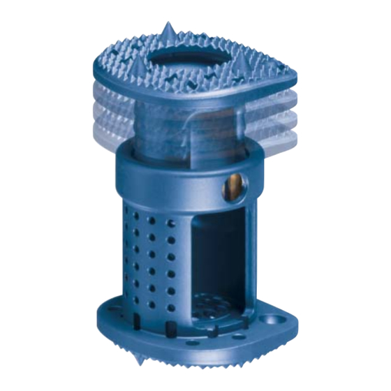
– Implants made from titanium alloy (Ti-6Al-7Nb) Expansion mechanism – Self-locking ratchet – Each ratchet step equals 2.5 mm of distraction – Rapid, controlled in situ expansion of the implant in the corpectomy site Synthes Spine Synex System Technique Guide... - Page 4 – Teeth and spikes designed to minimize implant migration – Kyphotic and lordotic configurations available – Open and closed endplates available Access for bone graft – Large window for internal bone graft placement after expansion – Endplate preserves space for peripheral bone graft placement Synthes Spine...
-
Page 5: Ao Principles
1. M.E. Müller, M. Allgöwer, R. Schneider, and H. Willenegger: AO Manual of Internal Fixation, 3rd Edition. Berlin; Springer-Verlag. 1991. 2. Ibid. 3. M. Aebi, J.S. Thalgott, and J.K. Webb. AO ASIF Principles in Spine Surgery. Berlin; Springer-Verlag. 1998. Synthes Spine Synex System Technique Guide... -
Page 6: Indications
The Synex implant can be packed with bone and should be used with Synthes supplemental internal fixation systems, such as TSLP, VentroFix, USS and Pangea. Synex implants are designed to provide anterior spinal column support even in the absence of fusion for a prolonged period. -
Page 7: Perform Corpectomy
Note: Remove the superficial layer of the cartilaginous endplates to expose bleeding bone. Excessive removal of subchondral bone may weaken the vertebral endplate. If the entire endplate is removed, subsidence and a loss of segmental stability may occur. Synthes Spine Synex System Technique Guide... -
Page 8: Determine Implant Size
Grasp the implant with the implant holder close to the locking ring, with the release opening facing the user. Note: For the smallest implants (495.315 and 495.316) place the implant holder close to the lower implant endplate (see Step 8 on page 10). Synthes Spine... -
Page 9: Fill With Bone Graft
Note: The optimal position for the implant is in the center of the vertebral endplate. Maintain space around the endplate of the implant to allow for peripheral bony fusion. Synthes Spine Synex System Technique Guide... -
Page 10: Attach Headpieces To Parallel Distractor
Use the headpieces labeled “B” for blue Synex implants and headpieces labeled Release button “G” for green Synex implants. for headpieces Note: After use, press the buttons on the distractor blades to remove the headpieces. Synthes Spine... -
Page 11: Expand Implant
11 (“Implant repositioning”) and replace it with an appropriately sized implant. When expanding the shorter Synex implants, the parallel distractor may press against the implant holder instead of the implant endplate. Synthes Spine Synex System Technique Guide... - Page 12 Introduce the disconnecting instrument into the slot between the two ends of the locking ring and turn it one-quarter (1/4) of a revolution. Remove the implant using the implant holder. Note: Do not reuse Synex implants once they have been implanted or expanded. Synthes Spine...
-
Page 13: Verify Locking Ring Is Closed
Radiographically verify the position of the implant in relation to the vertebral bodies in the frontal and sagittal planes intraoperatively. Pack bone graft in and around the cage, especially the anterior zone of the corpectomy site. Synthes Spine Synex System Technique Guide... -
Page 14: Apply Supplemental Fixation
Apply Supplemental Fixation Apply supplemental fixation To ensure stability of the spine and maintain adequate compression on the Synex construct, the Synex system is indicated for use with supplemental anterior and/or posterior fixation. The following systems may be used: VentroFix, TSLP, Pangea and/or USS. -
Page 15: Instruments
(a) on the shaft is visible. Turn the locking bolt (b) counterclockwise until it disconnects from the spreading instrument. Remove the locking bolt from the shaft. Disengage T-handle Disengage the T-handle from the hex-head (c) by pulling on the distractor blade. Synthes Spine Synex System Technique Guide... - Page 16 Remove T-handle Remove the T-handle by turning it clockwise until unthreaded and then pull it out of the shaft. Remove hex-head Remove the hex-head by turning it counterclockwise. Synthes Spine...
- Page 17 Synex Low Profile Parallel Distractor Disassembly and Assembly continued Assembly After cleaning, assemble the spreading instruments. Insert hex-head Thread the hex-head clockwise into the distractor blade until fully seated. Synthes Spine Synex System Technique Guide...
- Page 18 Insert T-handle Insert the T-handle into the distractor shaft and thread counter- clockwise to the red line. Attach the hex-head to the T-handle. Insert locking bolt Insert the locking bolt into the T-handle and turn clockwise until fully seated. Synthes Spine...
- Page 19 04.807.123 -5° 23 mm – 31 mm kyphotic 04.807.128 -5° 28 mm – 40 mm kyphotic 04.807.136 -5° 36 mm – 56 mm kyphotic 21 mm x 22 mm Note: Implants shown actual size. Synthes Spine Synex System Technique Guide...
- Page 20 04.807.233 10° 33 mm – 48 mm lordotic 04.807.237 20° 37 mm – 55 mm lordotic 25 mm x 28 mm 04.807.245 -6° 45 mm – 73 mm kyphotic - 6° 20° 10° 0° 495.319 495.323 495.327 495.321 Synthes Spine...
- Page 21 Instruments 389.193 Parallel Distractor 389.201 Disconnecting Instrument 389.204 Implant Holder 389.205 Small Headpieces, for use with Synex Parallel Distractor 389.206 Large Headpieces, for use with Synex Parallel Distractor Synthes Spine Synex System Technique Guide...
- Page 22 Also Available Instruments 01.807.003 Synex Endoscopic Spreader Instrument Set Note: For further information, please refer to the Endoscopic Spreader Instrument Set Assembly and Technique Guide. 389.202 Synex Low Profile Parallel Distractor For additional information, please refer to the package insert. Synthes Spine...
- Page 23 Synex System Instrument and Implant Set (145.305) Graphic Case 690.052 Synex System Instrument and Implant Set Graphic Case Instruments 389.193 Parallel Distractor 389.201 Disconnecting Instrument 389.204 Implant Holder 389.205 Small Headpiece, for use with Synex Parallel Distractor, 2 ea. 389.206 Large Headpiece, for use with Synex Parallel Distractor, 2 ea.
- Page 24 26 mm – 36 mm parallel 04.807.231 0° 31 mm – 46 mm parallel 04.807.233 10° 33 mm – 48 mm lordotic 04.807.237 20° 37 mm – 55 mm lordotic 04.807.245 -6° 45 mm – 73 mm kyphotic Synthes Spine...
- Page 25 To order: (800) 523-0322 To order: (800) 668-1119 Fax: (610) 251-9056 Fax: (905) 567-3185 www.synthes.com © 2001 Synthes, Inc. or its affiliates. All rights reserved. Pangea, Synex, VentroFix and Synthes are trademarks of Synthes, Inc. or its affiliates. Printed in U.S.A. 10/08 J3704-G...
Need help?
Do you have a question about the Synex System and is the answer not in the manual?
Questions and answers