Table of Contents
Advertisement
Quick Links
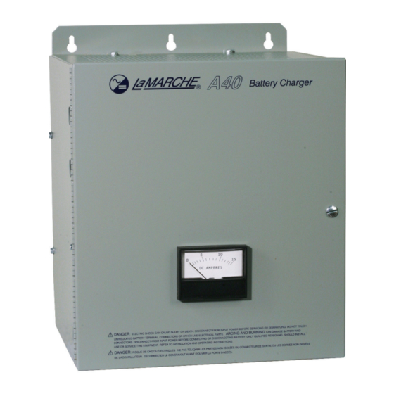
INSTALLATION AND OPERATING INSTRUCTIONS FOR MODEL A40/STANDARD - A40F/FILTERED
CPN100606
17832 – 4/08
17650 – 11/07
ISSUE DATE: 13578 – 12/99
MODEL
A40/A40F
INSTRUCTION
MANUAL
ECN/DATE
16837 - 6/05
15761 – 2/03
106 BRADROCK DRIVE
DES PLAINES, IL. 60018-1967
(847) 299-1188
FAX: (847) 299-3061
1 OF 12
15593 – 10/02
15349-02 – 5/02
INSTRUCTION DRAWING NUMBER:
P25-
18985 – 4/11
14575 – 2/01
13608 – 1/00
LA40-1
Advertisement
Table of Contents

Related Manuals for Lamarche A40


Summary of Contents for Lamarche A40
- Page 1 INSTALLATION AND OPERATING INSTRUCTIONS FOR MODEL A40/STANDARD - A40F/FILTERED MODEL A40/A40F INSTRUCTION MANUAL ECN/DATE CPN100606 18985 – 4/11 17832 – 4/08 16837 - 6/05 15593 – 10/02 14575 – 2/01 17650 – 11/07 15761 – 2/03 15349-02 – 5/02 13608 – 1/00 106 BRADROCK DRIVE DES PLAINES, IL.
-
Page 2: Important Safety Instructions
INSTALLATION AND OPERATING INSTRUCTIONS FOR MODEL A40/STANDARD - A40F/FILTERED IMPORTANT SAFETY INSTRUCTIONS SAVE THESE INSTRUCTIONS. This manual contains important safety and operating instructions. Before using this equipment, read all instructions and cautionary markings on (1) unit, (2) battery, and (3) product using the battery. -
Page 3: Receiving Instructions
INSTALLATION AND OPERATING INSTRUCTIONS FOR MODEL A40/STANDARD - A40F/FILTERED RECEIVING INSTRUCTIONS GENERAL EQUIPMENT INFORMATION CAUTION: To ensure safe installation and operation, the information given in the instruction manual should be read and understood before installing or using the equipment. RECEIVING INSTRUCTIONS Unpacking and Inspection: Examine the shipping crate upon arrival. - Page 4 INSTALLATION AND OPERATING INSTRUCTIONS FOR MODEL A40/STANDARD - A40F/FILTERED ***CAPACITOR PRE-CHARGE INSTRUCTIONS*** WARNING: READ INSTRUCTIONS BEFORE CONNECTING BATTERY FOR FILTERED UNITS To prevent the DC output fuse from blowing when connecting the battery, connections to the battery charger and batteries should be done in the following order (single battery charger).
- Page 5 (gassing) use of water and battery heating. The Model A40F is similar to the Model A40, except it's output is filtered. It can be used with all types of batteries, sealed maintenance free, valve regulated lead acid (VRLA) or standard flooded types.
-
Page 6: Installers Information
INSTALLATION AND OPERATING INSTRUCTIONS FOR MODEL A40/STANDARD - A40F/FILTERED INSTALLERS INFORMATION The table below lists the AC and the DC minimum wire size requirements. At distances exceeding 10 feet, the DC wire size should be chosen to keep the voltage difference between the unit's terminals and the battery at less than 1/2 volt when the unit is fully loaded. -
Page 7: Power Cabling Formulas
INSTALLATION AND OPERATING INSTRUCTIONS FOR MODEL A40/STANDARD - A40F/FILTERED POWER CABLING FORMULAS WIRE GAUGE TABLE AREA AREA SIZE CIR. SIZE CIR. MILS MCM* MILS 1620 250000 2580 300000 4110 350000 6530 400000 10380 500000 16510 600000 26240 700000 41740 750000... - Page 8 If the unit shuts down, the control panel may be defective. NOTE: The A40 battery charger is designed to maintain the battery at approximately 2.25 volts per cell lead (L) valve regulated lead acid (VRLA), and 1.47 volts per cell nickel cadmium (N). When the battery reaches this voltage, the charger should shut down to a small trickle charge.
- Page 9 INSTALLATION AND OPERATING INSTRUCTIONS FOR MODEL A40/STANDARD - A40F/FILTERED THE FOLLOWING INSTRUCTIONS ARE FOR USE BY QUALIFIED PERSONNEL. WARNING - THE FOLLOWING PROCEDURES WILL EXPOSE HAZARDOUS LIVE PARTS. DISCONNECT CHARGER BEFORE PROCEEDING. TROUBLESHOOTING INSTRUCTIONS AND DIODE REPLACEMENT The silicon diode may be a source of trouble. The function of the diode is to allow the flow of current through it in one direction only.
- Page 10 INSTALLATION AND OPERATING INSTRUCTIONS FOR MODEL A40/STANDARD - A40F/FILTERED General Maintenance Procedure Yearly 1. Blow out rectifier/inverter with a low-pressure air hose. 2. Make sure all connections are tight. 3. Perform a visual check on all internal components. 4. Check front panel meters and alarms for accuracy.
-
Page 11: Manufacturer's Standard Warranty
INSTALLATION AND OPERATING INSTRUCTIONS FOR MODEL A40/STANDARD - A40F/FILTERED MANUFACTURER’S STANDARD WARRANTY F OUR INVOICE TO YOU SHOWS THAT YOU HAVE PURCHASED THE XTENDED ARTS ARRANTY OR IF YOU ARE INTERESTED IN ’ PURCHASING THE XTENDED ARTS ARRANTY SEE THE... -
Page 12: Manufacturer's Extended Parts Warranty
INSTALLATION AND OPERATING INSTRUCTIONS FOR MODEL A40/STANDARD - A40F/FILTERED MANUFACTURER’S EXTENDED PARTS WARRANTY HIS IS YOUR ARRANTY IF YOU HAVE PURCHASED THE XTENDED ARTS ARRANTY AS SHOWN ON OUR INVOICE TO YOU OR IF YOU PURCHASE THE XTENDED ARTS ARRANTY ANYTIME DURING THE FIRST...
Need help?
Do you have a question about the A40 and is the answer not in the manual?
Questions and answers