Table of Contents
Advertisement
La Marche Manufacturing Company
www.lamarchemfg.com
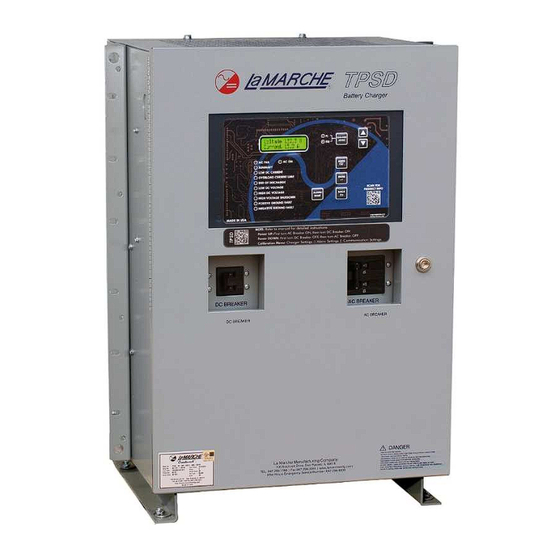
TPSD2
Filtered Battery Charger
Power Supply / Battery Eliminator
106 Bradrock Dr. Des Plaines 60018-1967
Tel: 847 299 1188
Fax: 847 299 3061
Standard
Installation and Operation Manual
Option 551
CPN 140440
Instruction Drawing Number: P25-LTPSD2-1
Revision A00
Rev. Date: 03/19
1
ECN: 22150
Advertisement
Table of Contents
Troubleshooting


Need help?
Do you have a question about the TPSD2 Standard Series and is the answer not in the manual?
Questions and answers