Table of Contents
Advertisement
Quick Links
Advertisement
Table of Contents
Troubleshooting

Related Manuals for Lamarche SGC


Summary of Contents for Lamarche SGC
- Page 1 La Marche Manufacturing Company www.lamarchemfg.com SCR Stationary Battery Charger Installation and Operation Manual 106 Bradrock Dr. Des Plaines, IL 60018-1967 137791 Instruction Drawing Number: P25-LSGC-1 Tel: 847 299 1188 Fax: 847 299 3061 Revision: A00 Rev. Date: 12/20 ECN: 21664...
- Page 2 Important Safety Instructions Before using this equipment read all manuals and other documents related to this charger and other equipment connected to this charger. Always have a copy of a charger’s manual on file nearby, in a safe place; if a replacement copy of a manual is needed, it can be found at www.lamarchemfg.com.
- Page 3 Charger Location • Allow at least 3 inches of free air on all vented surfaces (and external heatsinks) for proper cooling. • Allow sufficient clearance to open the front panel for servicing. • Do not operate this charger in a closed-in area or restrict ventilation in any way. •...
-
Page 4: Table Of Contents
Controls ...........................12 Configuration Mode ..........................13 Service ..............................16 Performing Routine Maintenance ....................16 Troubleshooting Procedure ......................17 Troubleshooting Chart ........................18 Appendix A: SGC Configuration Menu Structure ....................19 Appendix B: SGC Specifications........................20 Appendix C: Manufacturer’s Warranty ......................21 Appendix D: Document Control and Revision History ..................22... -
Page 5: Model Scope/General Description
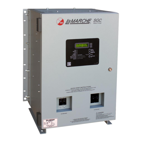
The SGC features adjustable Float and Equalize voltages, soft start, equalize timer, and is configurable for Flooded Lead Acid, NiCad or VRLA batteries. The SGC offers both AC and DC breakers as standard equipment. The SGC is equipped with a two-line LCD display which shows output voltage and current, along with an alarm status text description. -
Page 6: Equipment Handling
Storing the SGC If the SGC is to be stored for more than a few days after delivery, it should be stored within its shipping container. The location chosen for storage should be within an ambient temperature of -40 to 185°F (-40 to 85°C) with a non-condensing relative humidity of 5 to 95%. -
Page 7: Floor Mounting The Sgc
2.1.2 Floor Mounting the SGC To floor-mount the SGC, install four anchor bolts into the floor. Place the charger on the anchor bolts, add appropriate mounting hardware onto the floor-mounting anchor bolts, and tighten securely. Refer to Figure 3 for hardware specifications and floor-mounting dimensions. -
Page 8: Rack Mounting (4 Enclosure Only)
2.1.3 Rack Mounting (4 Enclosure Only) The SGC can be installed in most relay racks with standard EIA hole spacing. If a relay rack is needed, they are available for purchase from La Marche. The 4 enclosures are shipped from the factory with the necessary brackets installed for rear mounting on a 19”... -
Page 9: Ac Input Connections
For 120 VAC Input Voltage: Connect wire marked A to terminal TB3-8 Connect wire marked B to terminal TB3-10 Connect wire marked C to terminal TB3-6 Connect wire marked D to terminal TB3-10 AC input 1 connects to terminal TB1-1 (Line) AC input 2 connects to terminal TB1-3 (Neutral) For 208 VAC Input Voltage: Connect wire marked A to terminal TB3-9... -
Page 10: Output Connections
Output Connections Select proper size for the DC wiring from the wire size table on the previous page. If the distance between the charger’s DC output and the DC load exceeds 10 feet, use the Power Cabling Guide on the next page to minimize the voltage drop across the wire distance. -
Page 11: Alarm Connections
2.5.1 Standard Alarms Four alarm relays (and 6 alarm LEDs) are included as a standard feature of the SGC. The included alarm relays are High DC Voltage, Low DC Voltage, Summary, and AC Failure. Each alarm includes a form “C” contact, enabling the user to connect remote annunciators. - Page 12 All alarms contacts for the SGC are designed to be fail-safe. In other words, if both the AC and DC power are removed, each alarm will be indicating in its correct state. All relay contacts are shown in the de-energized state on schematics.
-
Page 13: External Temperature Compensation Connections (Option 11W/11Y)
External Probe Connection Procedure Before making any connections to the SGC, ensure that the AC Power is off at the main breaker box and that both of the charger’s breakers are off. Verify that no voltage is present by using a voltmeter at all input and output terminals. -
Page 14: Ground Detection Connection
Ground Detection Connection Procedure Before making any connections to the SGC, ensure that the AC Power is off at the main breaker box and that both of the chargers’ breakers are off. To disable Ground Detection, move the green Ground Detection wire to the GND DETECT-DEFEAT terminal of the CN10 connector on the S2A-431 board. -
Page 15: Operation
Factory Settings The factory settings of the SGC are based on the customer order, unless otherwise specified. All chargers are set at the factory with the following default settings. -
Page 16: Front Panel Display
Front Panel Display After the SGC has completed start up, the “AC ON” indicator on the front panel and either the “Float” or “Equalize” indicator on the front panel will be lit. The LCD will display the system DC output voltage and DC output current on line one. -
Page 17: Configuration Mode
– The back button allows the user to navigate to a previous screen or out of the configuration. Holding the back button will reset the charger. Upon restarting, the SGC will once again go through the start-up sequence described in Section 3.1.3. - Page 18 Temperature Compensation – Allows enable or disable of the Temperature Compensation feature. • Select TEMP. COMP. from Configuration Menu Select DISABLE or ENABLE NOTE: For internal compensation, enable the setting and place JP4 jumper across pins 1 and 2. For external compensation, disable the setting and place jumper across 2 and 3 (refer to Figure 10 and 11).
- Page 19 – Allows the user to change the serial number associated with the S2A-431 control board. This serial number is the serial number of the SGC charger and is set at the factory for new chargers. If a user receives a replacement S2A-431 board, the serial number may have to be set via calibration.
-
Page 20: Service
Before working inside the SGC, ensure that the AC Power is off at the main breaker box and that both of the charger’s breakers are off. Verify that no voltage is present by using a voltmeter at all input and output terminals. -
Page 21: Troubleshooting Procedure
Troubleshooting Procedure Troubleshooting should be performed only by trained service personnel or experienced electricians. Before setting up any complicated testing or making conclusions, inspect the charger using the guide below. Check the following: 1. Check DC output cables, connections, battery type, and number of cells against the charger’s rating. 2. -
Page 22: Troubleshooting Chart
Troubleshooting Chart Isolate from all power sources prior to performing any interior verifications or part replacements. Symptom Possible Cause Wrong AC Input Voltage Frequency out of Range AC Breaker Trips (High Input Current) Internal Wiring Failure Defective Component on Heatsink Assembly No AC Power Connected AC Mains Fail Alarm Incorrect Input AC Voltage Tap Setting... -
Page 23: Appendix A: Sgc Configuration Menu Structure
Appendix A: SGC Configuration Menu Structure Configure/OK Number of Cells Lead Acid Type 5-6 (12V) / 10-12 (24V) / 20-26 (48V) / 53-62 (130V) Nickel Cadmium Type 9-10 (12V) / 18-20 (24V) / 36-40 (48V) / 85-98 (130V) Float Voltage x.xx Volts per Cell... -
Page 24: Appendix B: Sgc Specifications
Appendix B: SGC Specifications ELECTRICAL Voltage Range ± 10% AC Input Frequency Range 50/60Hz DC Output 16 or 25 ADC @ 125 VDC Output Filtering Less than 500mV RMS, with connected battery ± 0.5% from no load to full load over the specified input Regulation voltage, frequency and ambient temperature range. -
Page 25: Appendix C: Manufacturer's Warranty
Appendix C: Manufacturer’s Warranty All La Marche Manufacturing Co. equipment has been thoroughly tested and found to be in proper operating condition upon shipment from the factory and is warranted to be free from any defect in workmanship and material that may develop within two (2) years from date of purchase. Any part or parts of the equipment (except fuses, DC connectors and other wear-related items) that prove defective within a two (2) year period shall be replaced without charge providing such defect, in our opinion, is due to faulty material or workmanship and not caused by tampering, abuse, misapplication or improper... -
Page 26: Appendix D: Document Control And Revision History
Appendix D: Document Control and Revision History Part Number: 137791 Instruction Number: P25-LSGC-1 Issue ECN: 21664 21664 – 12/20...
Need help?
Do you have a question about the SGC and is the answer not in the manual?
Questions and answers