Advertisement
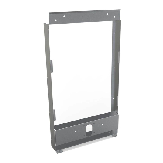
MFWSF100 / MFWSF120 MOUNTING FRAME INSTRUCTIONS
MFWSF120
5/16" SCREWS OR BOLTS
5/16" SCREWS OR BOLTS
(10 REQ'D - NOT FURNISHED)
(10 REQ'D - NOT FURNISHED)
INSTALL (2) SCREWS
(P/N: 111008343890 - PROVIDED)
(P/N 111008343890) IN FRAME
BEFORE INSTALLING IN OPENING
BEFORE INSTALLING IN OPENING
Elkay - www.elkay.com
Halsey Taylor - www.halseytaylor.com
FRAME
FRAME
INSTALL (2) SCREWS
MFWSF100
For Technical Service, please contact us at 1.800.476.4106
GROUND SCREW LOCATION
OUTLET BOX
18 3/4"
476mm
1000001943 (Rev. C - 03/19)
3"
76mm
31 3/4"
806mm
25"
635mm
Advertisement
Table of Contents

Summary of Contents for Elkay MFWSF100
- Page 1 MFWSF100 / MFWSF120 MOUNTING FRAME INSTRUCTIONS GROUND SCREW LOCATION OUTLET BOX MFWSF120 3" 76mm 5/16" SCREWS OR BOLTS 5/16" SCREWS OR BOLTS (10 REQ'D - NOT FURNISHED) (10 REQ'D - NOT FURNISHED) 31 3/4" FRAME 806mm FRAME INSTALL (2) SCREWS...
- Page 2 MFWSF100 / MFWSF120 MOUNTING FRAME INSTRUCTIONS 1. Cut a square rectangular wall opening 18 3/4” (476mm) W x 31 3/4” (806mm) H and 25” (635mm) above the floor line. These dimensions are required to obtain proper rim and bubbler heights for compliance with ANSI standard A117.1.


Need help?
Do you have a question about the MFWSF100 and is the answer not in the manual?
Questions and answers