Table of Contents
Advertisement
Quick Links
Mark 7® 1050 PRO Autodrive
(Supports Dillon 1050 Super, RL1050, RL1100 and
Read this manual and the Dillon Precision Press Manual completely. Understand all safety
and operating instructions. Failure to comply with the warnings and instructions may
result in serious injury, illness or death.
MARK 7® RELOADING 1050 USER MANUAL VERSION 9.3, COPYRIGHT 2020 ALL
RIGHTS RESERVED
User Manual
CP2000 Presses)
v 9.3
1
Advertisement
Table of Contents

Related Manuals for Mark 7 1050 PRO Autodrive


Summary of Contents for Mark 7 1050 PRO Autodrive
- Page 1 Read this manual and the Dillon Precision Press Manual completely. Understand all safety and operating instructions. Failure to comply with the warnings and instructions may result in serious injury, illness or death. MARK 7® RELOADING 1050 USER MANUAL VERSION 9.3, COPYRIGHT 2020 ALL RIGHTS RESERVED...
-
Page 2: Table Of Contents
1050 Safety Shield with Electronic Disconnect (Optional)………………………………………………………………. 53 Operating Instructions: 1050 PRO ......................56 Sofware Firmware Updates ........................63 Autodrive Maintenance Intervals ....................... 69 Dillon 1050 SUPER Lubrication Points......................69 Mark 7® Reloading 1050 User Manual version 9.3, Copyright 2020 All rights reserved... -
Page 3: Important Safety Instructions
WARNING – Activities using the Mark 7® 1050 Autodrive are inherently dangerous and may lead to injury and even death. Actions as a result of using the Mark 7® product are solely the responsibility of the user – if you get injured through the reloading process or through the use of ammunition as a result of the reloading process it is your fault. - Page 4 WARNING - Never leave your Mark 7® Autodrive unattended while it is operating. WARNING – Never run the Mark 7® Autodrive without the belt guard fully attached to the baseplate. WARNING – Never operate the Mark 7® Autodrive unless it is completely within Dillon Precision factory specifications and is operating within factory parameters.
- Page 5 WARNING – The Mark 7® Autodrive is designed to help automate the process of loading and processing of ammunition. Never operate the Mark 7® Autodrive at speeds higher than you have tested and are comfortable with for the type of reloading or processing that you are undertaking. Run the Mark 7®...
-
Page 6: Box Contents
EMI Filter kit for case feeder and Bulletfeeder (1X) • MicroSD Card for software updates (1X) Top Insert: (4 items) • Tablet (1X) • Belt (1X) • Belt guard (1X) • Setup instructions (1X) Mark 7® Reloading 1050 User Manual version 9.3, Copyright 2020 All rights reserved... -
Page 7: Set-Up Procedures
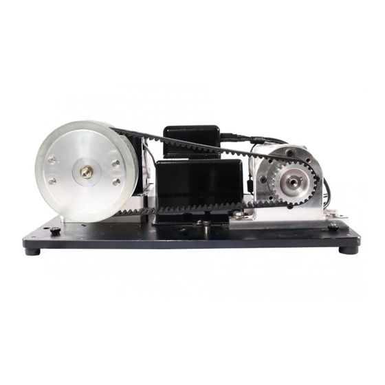
1. Ensure that the press/autodrive combination is on a very solid surface that does not move. The Mark 7 autodrive is designed to sit on the 4 rubber feet in the corners, but it can also directly bolted to your work bench by removing the 4X rubber feet in the corners, use ¼-20 bolts to fasten the baseplate to the work surface from underneath. - Page 8 Major system components listed below Motor Gear Box Drive Sprocket Motor Mount Belt Tensioning Shoulder Bolt Electronics Console Base Plate Rubber Feet (4 Corners) Figure 1: Major Component Overview Mark 7® Reloading 1050 User Manual version 9.3, Copyright 2020 All rights reserved...
- Page 9 Once mounted articulate the handle so that the press is at the top of stoke and proceed to loosen and remove the set screw that holds the handle in place. MARK 7® RELOADING 1050 USER MANUAL VERSION 9.3, COPYRIGHT 2020 ALL RIGHTS RESERVED...
-
Page 10: Mounting Large Sprocket
Then insert the sprocket cap and fasten with the ⅜ nut. Torque to 4-5 ft lb (5.5- 6.5 Nm). Torque both 1/4 -20 screws 4-5 ft. lbs. (5.5-6.5 Nm). Mark 7® Reloading 1050 User Manual version 9.3, Copyright 2020 All rights reserved... -
Page 11: Belt Installation
WARNING The press may rotate back to the up position so you may need an assistant to hold it in position. MARK 7® RELOADING 1050 USER MANUAL VERSION 9.3, COPYRIGHT 2020 ALL RIGHTS RESERVED... -
Page 12: Belt Tensioning
– when tensioned properly it should be tight with just a little flexibility from the rubber material – you should be able to push down on the belt and it should feel firm. Mark 7® Reloading 1050 User Manual version 9.3, Copyright 2020 All rights reserved... -
Page 13: Belt Guard Installation
For RL 1100/CP2000 use 3X 7/8” high Spacers and 3X 1-1/8” long Thumb Screws from Hardware Kit provided. WARNING Never operate the machine without the belt guard installed properly. MARK 7® RELOADING 1050 USER MANUAL VERSION 9.3, COPYRIGHT 2020 ALL RIGHTS RESERVED... - Page 14 Figure 8: Removing Ratchet arm In order to use the Jog functionality of the Mark 7® Autodrive the ratcheting system on the Dillon must be removed – but that is a decision best made by the user. You can either choose to remove the ratchet arm Dillon Part #13376 or the toolhead ratchet Dillon Part #11688 or both (recommended) as shown above.
- Page 15 The correct resolution of this is to turn the press off, remove the power cord. Manually manipulate the press to fix the impacted areas, clear the press, and start the loading process again while discarding the affected rounds. MARK 7® RELOADING 1050 USER MANUAL VERSION 9.3, COPYRIGHT 2020 ALL RIGHTS RESERVED...
-
Page 16: Tablet Holder Install
Do not zip tie the tablet cables to Dillon case feeder pole, case feeder power cord or Mr. Bulletfeeder power cords. Mark 7® Reloading 1050 User Manual version 9.3, Copyright 2020 All rights reserved... - Page 17 There are 2 sets of right angle adapters, the short adapters are used on the 7” and 10” tablets and the longer adapters are used on the 9”. MARK 7® RELOADING 1050 USER MANUAL VERSION 9.3, COPYRIGHT 2020 ALL RIGHTS RESERVED...
-
Page 18: Tablet Cable Outlet Installation
The best vantage point for this is standing immediately in front of the press. Mark 7® Reloading 1050 User Manual version 9.3, Copyright 2020 All rights reserved... -
Page 19: Console Rear I/O Inputs
Micro 8-Pin Figure 14: Rear of console Inputs Before powering on the Mark 7 Units please make the following connections Micro-USB: Tablet to Console USB data communication cable USB: Motor to Console USB data communication cable 8-Pin: Motor to console signal cable Port #7. -
Page 20: Console Side I/O Inputs
Never power on the console switch without the 6-pin molex connector plugged in and never install this connector with the power already on since the DC voltage would damage the motor's input contacts. Mark 7® Reloading 1050 User Manual version 9.3, Copyright 2020 All rights reserved... - Page 21 12. EMI Filter for Mr.BulletFeeder and GSI Bulletfeeder Users There is a external capacitor cable assembly included with your Mark 7® Autodrive. Ensure that this is attached to the bullet dropper assembly between that assembly and the cables to the bullet feeder to ensure error-free operation.
- Page 22 WARNING – Use of the RC filter is at your risk and only for those experienced with electrical systems and is only for the systems that are experiencing interference*. Mark 7® Reloading 1050 User Manual version 9.3, Copyright 2020 All rights reserved...
- Page 23 Plug the Power lines into the corresponding male terminal leads on the RC filter terminals as shown below. 4. Reinstall cover plate and test for proper operation. Connection at Micro-switch Connection at On/Off Switch Figure 18: Case Feeder RC Filter MARK 7® RELOADING 1050 USER MANUAL VERSION 9.3, COPYRIGHT 2020 ALL RIGHTS RESERVED...
- Page 24 TABLET USB and POWER cable on left side floating Mr. Bullet controller feeder mounted away from tablet. Figure 19: Recommended cable management front view Mark 7® Reloading 1050 User Manual version 9.3, Copyright 2020 All rights reserved...
- Page 25 Case Feeder and Mr. Bulletfeeder power cords coming straight back away from machine. Mr. Bullet feeder controller mounted to the side or behind machine Figure 20: Cable Management Side View MARK 7® RELOADING 1050 USER MANUAL VERSION 9.3, COPYRIGHT 2020 ALL RIGHTS RESERVED...
- Page 26 Figure 21: Remote Tablet Mount (Optional) Mark 7® Reloading 1050 User Manual version 9.3, Copyright 2020 All rights reserved...
- Page 27 • No cables are near the moving parts of the 1050, secure any loose cables away from the moving components Figure 22: Manually driving the 1050 Press MARK 7® RELOADING 1050 USER MANUAL VERSION 9.3, COPYRIGHT 2020 ALL RIGHTS RESERVED...
- Page 28 Figure 24: New Style mounted Left, Old style Mounted Right It may be required to bend up the arm on the micro switch and to add a weight to the primer follower Mark 7® Reloading 1050 User Manual version 9.3, Copyright 2020 All rights reserved...
- Page 29 WARNING –Use of the Mark 7® DecapSense™ is at your risk and only for expert reloaders. The Mark 7® DecapSense™ is designed for both the Dillon 1050 Super and Dillon 1050 RL machines. Please confirm you have received the correct mount: SUPER Figure 25: 1050 SUPER/CP 2000, RL 1100 (left) and RL 1050 (Right) DecapSense™...
- Page 30 3. Attach the hose and route into a bucket or other spent primer collection container. 4. Plug the Mark 7® DecapSense into the connector on the console at port#5 as shown in section DecapSense™ Operating Instructions 1.
- Page 31 Mark 7® DecapSense™ shown below and resume normal operation. Figure 27: Sensor Obstructed Cleaning required Message 3. To clean the sensor use compressed air to blow into the port on the front of the sensor as shown in figure 27.
- Page 32 The Mark 7® SwageSense® package includes: • Mark 7® SwageSense® • Small Primer Swage Rod • Large Primer Swage Rod • Cable Management anchors and zip ties • .05” Allen Key Mark 7® Reloading 1050 User Manual version 9.3, Copyright 2020 All rights reserved...
- Page 33 The Mark 7® SwageSense® comes pre-installed with the smaller primer swage rod. If you are installing on a 1050 setup with large primers replace the upper swage rod before installing on the 1050. Installation Instructions 1. First make sure you have software and firmware listed below (or newer) before installing SwageSense®...
- Page 34 Make sure you leave enough play in the wires for the swage assembly to move up and down during machine operation, see below. Figure 32: Cable assembly with strain relief, Port to plug into console. Mark 7® Reloading 1050 User Manual version 9.3, Copyright 2020 All rights reserved...
- Page 35 5/16 wrench thread the swage rod up until it bottoms out into the case pocket. Then turn it a ¼ turn more and lock down the jam nut. See the figure below. Figure 33: Cross-section of properly adjusted Swage Rod MARK 7® RELOADING 1050 USER MANUAL VERSION 9.3, COPYRIGHT 2020 ALL RIGHTS RESERVED...
- Page 36 Figure 34: Micro switch Adjustment 3. When the SwageSense® switch is triggered the following notification will appear on the reloader application. Figure 35: SwageSense® Notification (1050 PRO Control screen shown) Mark 7® Reloading 1050 User Manual version 9.3, Copyright 2020 All rights reserved...
- Page 37 3. The Mirror Mount is shipped with a protective film over the surface, before starting setup, peel off the film. If required the Mirror surface should be cleaned with water or isopropyl alcohol, do not use any other types of solvents. MARK 7® RELOADING 1050 USER MANUAL VERSION 9.3, COPYRIGHT 2020 ALL RIGHTS RESERVED...
- Page 38 Installing BulltetSense® Main Assembly: 1. First remove the bin support 3/8” pan head socket cap screw using a 7/32” Allen key Figure 38: Removing Bin Support Screw. Mark 7® Reloading 1050 User Manual version 9.3, Copyright 2020 All rights reserved...
- Page 39 #7 or station #8. If you are running a Dillon powder check or a Mark 7 PowderSense® you must configure the mount for station #8. If you are not running a powder check configure the mount for station # 7.
- Page 40 3. Remove the 2X 5/16” threaded dowel pins from the upper mount. Use a ¼” wrench to remove the pins from the lower mount and thread them into the desired mounting configuration shown in the next figures. Figure 41: Removing the 5/16” dowel pins Mark 7® Reloading 1050 User Manual version 9.3, Copyright 2020 All rights reserved...
- Page 41 Then remove the priming mechanism and slide it off the primer tube. Sometimes a flat screw driver is needed to open up the clamp for easier removal. MARK 7® RELOADING 1050 USER MANUAL VERSION 9.3, COPYRIGHT 2020 ALL RIGHTS RESERVED...
- Page 42 NOTE: Due to variations in the Dillon priming tube it may be necessary to wrap a then section of tape around the tube to achieve a tighter clamp, do not over tighten the screws. Figure 44: Mounting the mirror for Station 7 Mark 7® Reloading 1050 User Manual version 9.3, Copyright 2020 All rights reserved...
- Page 43 Once the reflected laser beam appears on the sensor main body, continue adjusting the set screws to direct the laser beam into the sensor hole as shown in the following figures. MARK 7® RELOADING 1050 USER MANUAL VERSION 9.3, COPYRIGHT 2020 ALL RIGHTS RESERVED...
- Page 44 Figure 46: Adjust the set screw to align the laser. Before adjustment (Left) Mid Adjustment (Right) Figure 47: After Adjustment Mark 7® Reloading 1050 User Manual version 9.3, Copyright 2020 All rights reserved...
- Page 45 When the bullet is not present, upside or sideways the beam will pass over the bullet and contact the sensor triggering the machine to stop. MARK 7® RELOADING 1050 USER MANUAL VERSION 9.3, COPYRIGHT 2020 ALL RIGHTS RESERVED...
- Page 46 BulletSense® assembly for press maintenance or for any reason you can choose to remove the upper mount only. When re-installing, the vertical position will be maintained. Figure 50: Locking height adjustment in place Mark 7® Reloading 1050 User Manual version 9.3, Copyright 2020 All rights reserved...
- Page 47 1050 frame. Figure 51: Removing the shoulder bolt to mount on station 8 adapter. Figure 52: Mounting station 8 adapter to the 1050 frame. MARK 7® RELOADING 1050 USER MANUAL VERSION 9.3, COPYRIGHT 2020 ALL RIGHTS RESERVED...
- Page 48 Adjust the height of the Upper Mount so the laser beam goes over the projectile and then hits the tip of the back side of the bullet. • Lock Upper Mount and Mirror Mount in position. Mark 7® Reloading 1050 User Manual version 9.3, Copyright 2020 All rights reserved...
- Page 49 4. Perform a system calibration the go to the sensors tab and make sure BulletSense® is enabled. 5. Press RUN or Single Cycle. With a clear shell plate the following notification should appear stating that a “Bullet Not Properly Positioned.” MARK 7® RELOADING 1050 USER MANUAL VERSION 9.3, COPYRIGHT 2020 ALL RIGHTS RESERVED...
- Page 50 Figure 55: Sensor Page (enable BulletSense®) Figure 56: BulletSense® Notification Mark 7® Reloading 1050 User Manual version 9.3, Copyright 2020 All rights reserved...
- Page 51 Powder check Installation instructions are included with the powder check sensor. Plug the PowderSense into Port #7. Please refer to the console input section for more detailed information Figure 57: PowderSense® Complete Kit MARK 7® RELOADING 1050 USER MANUAL VERSION 9.3, COPYRIGHT 2020 ALL RIGHTS RESERVED...
- Page 52 For GSI bullet feeders you run the powder check along with separate seating and crimp dies. Figure 58: PowderSense® with Mr. Bulletfeeder and Redding seat/crimp combo die Mark 7® Reloading 1050 User Manual version 9.3, Copyright 2020 All rights reserved...
- Page 53 Install the shield hinges to the 1050 Pole as shown below. Once the shield is installed they can be adjusted to the proper level. Figure 59: Shield Hinges on 1050 post MARK 7® RELOADING 1050 USER MANUAL VERSION 9.3, COPYRIGHT 2020 ALL RIGHTS RESERVED...
- Page 54 Shield Cable STOP REMOTE STOP Figure 61: Cable Assembly Mark 7® Reloading 1050 User Manual version 9.3, Copyright 2020 All rights reserved...
- Page 55 The JOG functions are not disabled and the tool head can repositioned using those commands or by press STOP twice and manually actuating the large sprocket with a 5/8” wrench. Figure 63: Shield Open Notification MARK 7® RELOADING 1050 USER MANUAL VERSION 9.3, COPYRIGHT 2020 ALL RIGHTS RESERVED...
- Page 56 Reloader, firmware and software applications. Before selecting the Reloader application, make sure the console is powered on, all system cables are connected and the shell plate is clear. Mark 7® Reloading 1050 User Manual version 9.3, Copyright 2020 All rights reserved...
- Page 57 Figure 65: System Waiver Screen (1050 PRO SHOWN) Following proper installation of the Mark 7® Autodrive the user will be able to power up their tablet and console to launch the Mark 7® Autodrive application. The image above is the first screen the operator will see.
- Page 58 Figure 66: System Control Screen (1050 PRO shown above) CALIBRATE - The function is the first operation that must be run before fully running the Mark 7® Autodrive. CALIBRATE signals the Mark 7® Autodrive to find the top and bottom of the presses stroke.
- Page 59 JOG UP - The JOG UP function will incrementally move the press upwards. The JOG UP functions is useful in clearing jams that may occur. The JOG UP function will only work when the Mark 7® Autodrive is at a stop.
- Page 60 SET PRIMER - The operator has the ability to set the number of primers used before the Mark 7® Autodrive ends its current run. SET BRASS - The operator has the ability to set the number of brass used before the Mark 7® Autodrive ends its current run.
- Page 61 We recommend disabling any of the sensors you don’t have installed on your system. RUN, END CYCLE, and STOP functions have the same functionality on the Setup Screen as they do on the Control Screen and the Monitors Screen MARK 7® RELOADING 1050 USER MANUAL VERSION 9.3, COPYRIGHT 2020 ALL RIGHTS RESERVED...
- Page 62 RUN, END CYCLE, and STOP functions have the same functionality on the Setup Screen as they do on the Control Screen and the Monitors Screen Mark 7® Reloading 1050 User Manual version 9.3, Copyright 2020 All rights reserved...
- Page 63 *May only be included in some update packages 3. Inset the Micro SD card into the SD card adapter that was provided with the Mark 7® Autodrive and load the downloaded .hex and .apk file(s) onto the SD card via a SD card reader.
- Page 64 UPLOAD and press CLOSE when complete. Select the Reloader application and confirm that software version and firmware at the waiver screen is the same as what was just installed. Figure 72: Firmware installation Process Mark 7® Reloading 1050 User Manual version 9.3, Copyright 2020 All rights reserved...
- Page 65 Troubleshooting: software and firmware updates Selecting Firmware update flashes a black screen then goes back to the main screen. Make sure the Mark 7® console is powered on and the USB cable is connected between the tablet and console. Upgrading the firmware takes longer than 5 seconds or freezes.
- Page 66 3. Reposition the sprocket, tighten the set screw and re-install the belt and belt guard. Figure 74: Adjusting the small sprocket position on the gearbox shaft Mark 7® Reloading 1050 User Manual version 9.3, Copyright 2020 All rights reserved...
- Page 67 For best results replace the ¼-20 screw with a GRADE 8 Hex head screw and apply medium strength Loctite to the thread. Figure 75: Dillon1050 Super Bearing cap MARK 7® RELOADING 1050 USER MANUAL VERSION 9.3, COPYRIGHT 2020 ALL RIGHTS RESERVED...
- Page 68 4. While looking into the hole rotate the small sprocket very slowly. You will see the shaft collar spinning inside the hole 5. There are 2X Metric socket head cap screws clamping the gearbox shaft collar to the motor output shaft. Mark 7® Reloading 1050 User Manual version 9.3, Copyright 2020 All rights reserved...
- Page 69 • Lube the Indexing Lever Cam surface (#10064) and Index Lever Shoulder Bolt (#13276). With the handle in the rest position, you will see the Index Roller (#10996) come into contact with the Lever Cam MARK 7® RELOADING 1050 USER MANUAL VERSION 9.3, COPYRIGHT 2020 ALL RIGHTS RESERVED...
- Page 70 3. Turn off the power to the console of the autodrive 4. Turn off the power to the case feeder and the bullet feeder 5. Turn off the power to the tablet Mark 7® Reloading 1050 User Manual version 9.3, Copyright 2020 All rights reserved...
- Page 71 Calibration Calibration can only be done when the Mark 7® Autodrive is empty with no casings in the shell plate. Only after calibration is complete you may start reloading ammunition...
- Page 72 If you don’t get a notification make sure you have software 00.01.02 (9/27/2016) or newer. Mark 7® Reloading 1050 User Manual version 9.3, Copyright 2020 All rights reserved...
- Page 73 Digital Clutch being set too low for a given operation. We recommend taking the following steps when a jam occurs. MARK 7® RELOADING 1050 USER MANUAL VERSION 9.3, COPYRIGHT 2020 ALL RIGHTS RESERVED...
- Page 74 5/8” wrench. Once the jam is clear perform a full stroke manually before continuing. In some cases a hard jam may occur. If the jog buttons do not move the tool head then the Mark 7® Autodrive needs to be powered down. Once powered down may attempt to manually clear the jam. In doing so you must clear the shell plate and confirm that the press can manually index.
- Page 75 If this error occurs during machine operation and you have followed the above steps please contact us for technical support. MARK 7® RELOADING 1050 USER MANUAL VERSION 9.3, COPYRIGHT 2020 ALL RIGHTS RESERVED...
- Page 76 Refer to the knowledge base section on our website under SUPPORT for troubleshooting articles relating to setup and operation. http://www.markvii-loading.com/ Please contact us for technical support Phone: 1-239-349-7266 Hours: 8:00am-5:00pm, ET, M–F CRM: https://www.markvii-loading.com/crm.asp?action=contactus Mark 7® Reloading 1050 User Manual version 9.3, Copyright 2020 All rights reserved...
Need help?
Do you have a question about the 1050 PRO Autodrive and is the answer not in the manual?
Questions and answers