Table of Contents
Advertisement
Germany
ONLINE USV-Systeme AG
Luise-Ullrich-Str. 8
D-82031 Grünwald
Phone +49 (89) 2423990-10
Fax
+49 (89) 2423990-20
www.online-usv.de
Z800-3000_usermanual_engl_20170405.docx
User manual
ONLINE ZINTO-series
Models 800 – 3000
Italy
ONLINE UPS-Systems S.r.l.
Via Ferruccio Gilera 110
I-20862 Arcore (MB)
Phone +39 (039) 2051444
Fax
+39 (039) 2051435
www.online-ups.it
1 / 42
INTRODUCTION
Switzerland
ONLINE USV-Systeme AG
c/o POTESTA AG
Hertistrasse 29
8304 Wallisellen (Zürich)
Phone
+49 (89) 242399010
Fax
+49 (89) 242399020
www.online-usv.ch
Advertisement
Table of Contents
Troubleshooting

Subscribe to Our Youtube Channel
Related Manuals for Online USV ZINTO Series


Summary of Contents for Online USV ZINTO Series
-
Page 1: User Manual
INTRODUCTION User manual ONLINE ZINTO-series Models 800 – 3000 Germany Italy Switzerland ONLINE USV-Systeme AG ONLINE UPS-Systems S.r.l. ONLINE USV-Systeme AG Luise-Ullrich-Str. 8 Via Ferruccio Gilera 110 c/o POTESTA AG D-82031 Grünwald I-20862 Arcore (MB) Hertistrasse 29 8304 Wallisellen (Zürich) -
Page 2: Table Of Contents
INTRODUCTION Content User manual ..................1 Introduction ................. 5 Safety warnings ................7 Installation .................. 8 Checking the delivery ............8 Unpacking the UPS system ..........8 Checking the accessories ........... 9 Installation as tower, activating battery ....... 9 Installation in a rack, activating the batteries ....11 Getting started .............. - Page 3 INTRODUCTION Specification ..............37 Rear view ................39 CE confirmation ..............41 Warranty ................... 42 List of Illustrations Figure 1: Circuit diagram of principle ..........5 Figure 2: ZINTO 800 - 3000 in the rack ..........6 Figure 3: ZINTO 800 - 3000 as tower ..........6 Figure 4: Removing the frontpanel ...........
- Page 4 INTRODUCTION List of tables Table 1: Package contents ..............9 Table 2: Descriptions of display ............16 Table 3: Display ................18 Table 4: Acoustic alarm ..............18 Table 5: Overview of operating status ..........19 Table 6: Configuration menu ............20 Table 7: Pin assignment for RS-232 interface ........
-
Page 5: Introduction
INTRODUCTION 1. Introduction ONLINE USV-Systeme AG (ONLINE) is one of the leading manufac- turers of uninterruptible power supplies (UPS). Since 1988, the Ger- man company has focussed on the development, production, sale and support of UPS systems. Based on unit numbers sold, ONLINE prod- ucts are the German number one in the UPS market and internation- ally recognised because of their top quality and excellent support. -
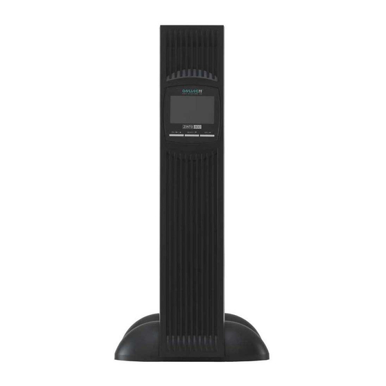
Page 6: Figure 2: Zinto 800 - 3000 In The Rack
INTRODUCTION The ZINTO also offers the following benefits: Rack-Tower-versatile model, only 2U Silent in normal operation Buck & Boost function for voltage regulation without battery Perfect sinewave output voltage Efficiency >97 % High active power due to Power factor 0.9 ... -
Page 7: Safety Warnings
SAFETY WARNINGS 2. Safety warnings This manual contains important instructions that you must follow dur- ing the installation and maintenance of the UPS system and the bat- teries. Please read all the instructions in the manual before working with the device. Keep the manual in a safe place. CAUTION ... -
Page 8: Installation
INSTALLATION 3. Installation 3.1 Checking the delivery Keep the transport box and the packaging material for the carrier or sales point. If parts of the system have been damaged in transit, sub- mit a transport damage complaint to your supplier within 24 hours. If you only discover damage after accepting the device, please submit a complaint for concealed damage. -
Page 9: Checking The Accessories
INSTALLATION 3.3 Checking the accessories Description 19" mounting bracket (left and right) Feet for tower mounting (sets) USB interface cable 10A IEC extension cable 16A mains cable Quick start guide DataWatch software* Manual* *Download from www.online-ups.com Table 1: Package contents 3.4 Installation as tower, activating battery The UPS system is delivered fully assembled. -
Page 10: Figure 4: Removing The Frontpanel
INSTALLATION Figure 5: Connecting the battery Figure 4: Removing the frontpanel 2. Connect two foot components to one foot (see Figure 6) and push the UPS system into the two feet from above (see Figure 7). Make sure the distance between the two feet is as great as possible to ensure stability. -
Page 11: Installation In A Rack, Activating The Batteries
INSTALLATION 3.5 Installation in a rack, activating the batteries The UPS system is delivered fully assembled. CAUTION The casing is very heavy (see Chapter 8 Technical Data). Optional slide rails (article no. Rack Kit) are available for the rack model. The slide rails fit 48 cm (19 inch) racks with a depth of 48 to 78 Fit the rack kit (separate assembly instructions provided with the rack kit). -
Page 12: Figure 10: Connect The Battery
INSTALLATION Figure 10: Connect the battery Figure 11: Mounting the frontpanel Finally, fit the front panel by reversing the sequence. Align the mounting bracket (L = left and R = right) with the screw holes on either side of the UPS system and affix it using the M4 x 8 countersunk screws provided. -
Page 13: Getting Started
INSTALLATION 3.6 Getting started PLEASE NOTE Make sure that the overall rated performance of the load con- nected does not exceed the capacity of the UPS system. The power consumption of inductive loads or laser printers can be very high, please take this into consideration when specifying your UPS system. - Page 14 INSTALLATION Starting in battery mode 1. Hold the “ON / MUTE” button on the UPS system down until you hear a beep. 2. The UPS system is starting, the display then shows the battery statuses (see Chapter 4.4 Operating statuses) and supplies the load connected with reliable power.
-
Page 15: Operation
OPERATION 4. Operation 4.1 Control panel The UPS system has a control panel with three buttons and a graph- ical display (see Figure 14). Figure 14: Control panel and display Button Function In standby mode: Press button for Switch on more than 2 seconds In battery mode: Press button for Alarm signal OFF... -
Page 16: Table 2: Descriptions Of Display
OPERATION In normal mode: Switching the dis- play from input voltage and fre- Switch over quency, battery voltage and capacity, UPS internal temperature, output SELECT / voltage, frequency and current, load In standby mode: Press button for Configuration mode longer than 2 seconds to start config- uration mode Down In configuration mode: Back to menu... -
Page 17: Display And Menu
OPERATION 4.2 Display and menu Symbol Description Function Pressing the SELECT button in normal mode Input, battery, displays the following measurements: temperature, out- Input voltage and frequency, battery voltage put, load and capacity, UPS internal temperature, out- put voltage, current and frequency, load in %. Autonomy time Display of remaining autonomy time Displays the current load. -
Page 18: Table 3: Display
OPERATION Symbol Description Function Output sockets Active UPS output Battery symbol in DC link: UPS system in bat- Battery tery mode Battery symbol in DC link: Battery in charging Battery charging mode The UPS system evens out low voltage in the Boost mode mains voltage without the battery The UPS system evens out high voltage in... -
Page 19: Settings
OPERATION Enable EPO / Emergency Power Off Temperature Table 5: Overview of operating status 4.3 Settings 1. Open configuration menu: Switch to standby mode and press button for 3 seconds. 2. Selection of menu options: Press button until you reach the menu option you want (see Table 6). -
Page 20: Table 6: Configuration Menu
OPERATION Setting Available options Standard “230V” Select output voltage: [208] = 208V [220] = 220V [230] = 230V [240] = 240V “DIS” Programmable output sockets: [ENA] = Enabled [DIS] = Disabled “999” Shutdown time for programmable output sockets: [0 - 999] = Shutdown of programmable output sockets in battery mode after time defined here. -
Page 21: Operating Statuses
OPERATION 4.4 Operating statuses The status of the UPS system is displayed on the control panel. Normal operating mode Figure 15: Normal mode display In normal mode, “OK” is shown on the display and the UPS system is fed by the supply network. The UPS system monitors the batteries and charges them as required. -
Page 22: Figure 17: Display In Standby Mode
OPERATION If the supply network is restored after the UPS system has shut down, the UPS is automatically restarted. The batteries are charged up and the load connected are supplied with power. Standby mode If the UPS system is switched off and the power supply cable is con- nected, the UPS system works in standby mode. -
Page 23: Communication And Interfaces
COMMUNICATION AND INTERFACES 5. Communication and interfaces 5.1 RS-232 and USB interface In order to establish communication between the UPS system and a computer, connect the computer using a suitable data cable (USB ca- ble provided) to the RS-232 or USB interface on the UPS system (see Chapter 8.2 Rear view). -
Page 24: Slot For Interface Cards
COMMUNICATION AND INTERFACES 5.2 Slot for interface cards The ZINTO features a slot (see Chapter 8.2 Rear view) for the follow- ing interface cards: Product no. Description DW7SNMP30 SNMP adapter Basic The SNMP adapter communicates via TCIP/IP with the load at- tached to the network. -
Page 25: Surge Voltage Protection For Data And Telephone Lines (Dsl / Telephone / Fax / Network)
COMMUNICATION AND INTERFACES CAUTION The emergency power off switch must not be connected to circuits which are connected to the supply network. Reinforced insulation from the network is required. The emergency power off switch must be designed for at least 60V DC / 30V AC and 20mA. -
Page 26: Datawatch Software
COMMUNICATION AND INTERFACES to the end device. The data connection protection cable protects net- works with a transfer rate of 10 to 1000 Mbit/s. 5.5 DataWatch software The ZINTO range is supplied as standard with DataWatch, a compre- hensive software solution for shutting down and managing the PC or server system and for monitoring the ZINTO and the power supply network. -
Page 27: Table 9: Overview Functions For Lcd And Datawatch
COMMUNICATION AND INTERFACES Configure and enable/disable the emergency power off function (EPO) Manual restart of the UPS system Signalling battery failure Advanced display of the total battery runtime Display of the serial number Local server shutdown via RS-232 / USB-interface Multi server shutdown via TCP/IP SNMP-proxy-agent Send E-Mail, SMS, broadcastmessages... -
Page 28: Maintenance
MAINTENANCE 6. Maintenance 6.1 Care and maintenance To ensure a long service life for the system, the area around the UPS system should be kept clean and free of dust. If the area around the system is very dusty, clean the external surfaces of the system with a vacuum cleaner. -
Page 29: Replacing The Batteries
MAINTENANCE 6.4 Replacing the batteries PLEASE NOTE Do not replace the batteries while the UPS system is in battery mode. The hot-swap functionality means the batteries can be replaced with- out first shutting down the UPS system and disconnecting the load. If you would prefer to disconnect the UPS system before changing the batteries, read Chapter 3.6 Getting started. -
Page 30: Figure 21: Removing The Front Panel
MAINTENANCE CAUTION DANGER OF ELECTRIC SHOCK. Never make changes to the battery cabling or connections. Attempting to change the battery cabling yourself could lead to serious injury. The batteries of the UPS system are very heavy. Be careful when handling heavy batteries. -
Page 31: Figure 22: Disconnecting The Battery Connector
MAINTENANCE 2. Disconnect the battery connector (see Figure 22) Figure 22: Disconnecting the battery connector 3. Remove the battery cover (see Figure 23). Figure 23: Removing the battery cover 4. Carefully remove the battery insert using the handle. 5. Replace the batteries in the battery insert. PLEASE NOTE ... -
Page 32: Testing The New Batteries
MAINTENANCE CAUTION A small arc can occur when the batteries are connected to the UPS system. This is normal and represents no risk to person- nel. Insert the battery cable quickly and firmly into the battery plug connection in the UPS system. 7. -
Page 33: Troubleshooting
TROUBLESHOOTING 7. Troubleshooting The ZINTO is designed for autonomous operation and automatically reports and problems in the display. 7.1 Error codes Error code Event Error starting the DC link DC link voltage too high DC link voltage too low Error starting inverter Inverter voltage too high Inverter voltage too low Short circuit in inverter output... -
Page 34: Troubleshooting
TROUBLESHOOTING Warning sound every 2 Charger error seconds Warning sound every 2 Battery error seconds Warning sound every 2 Replace battery seconds Warning sound every 2 EEPROM Error seconds Table 11: Warnings 7.3 Troubleshooting Operating status Possible cause Measure The UPS system cannot The input cable is not Check that both connect- be switched on, although... -
Page 35: Muting The Alarm
The alarm cannot be muted for alarm and error messages. 7.5 Support ONLINE USV-Systeme AG (ONLINE) is one of the leading manufac- turers of uninterruptible power supplies (UPS). Since 1988, the Ger- man company has focussed on the development, production, sale and support of UPS systems. - Page 36 TROUBLESHOOTING As a German provider, ONLINE guarantees direct approachability, simple processing and short response times. Comprehensive support is a matter of course - before and after purchase. ONLINE sets great store by reliable support and service. Free direct advice and support on: Software hotline: +49 (89) 242 39 90 - 13 Hardware hotline: +49 (89) 242 39 90 - 18...
-
Page 37: Technical Data
TECHNICAL DATA 8. Technical data 8.1 Specification Model ZINTO ZINTO ZINTO ZINTO ZINTO 1000 1500 2000 3000 Product no. Z800 Z1000 Z1500 Z2000 Z3000 Electrical characteristics Rated power (VA / W) 800 / 1000 / 1500 / 2000 / 3000 / 1350 1800 2700... -
Page 38: Table 13: Specification
TECHNICAL DATA Connections Input 1x IEC320 C20 1x IEC320 C14 (10A) (16A) Outputs, 10A 8x IEC320 C13 (10A) Output, 16A IEC320 (16A) Batteries Type Autonomy times at 50 14 / 6 19 / 7 23 / 10 17 / 6 17 / 6 and 100% load and pf=0.7 Battery type... -
Page 39: Rear View
TECHNICAL DATA 8.2 Rear view Figure 24: Rear view of ZINTO 800 - 1500 Figure 25: Rear view of ZINTO 2000 39 / 42 Z800-3000_usermanual_engl_20170405.docx... -
Page 40: Figure 26: Rear View Of Zinto 3000
TECHNICAL DATA Figure 26: Rear view of ZINTO 3000 40 / 42 Z800-3000_usermanual_engl_20170405.docx... -
Page 41: Ce Confirmation
TECHNICAL DATA 8.3 CE confirmation 41 / 42 Z800-3000_usermanual_engl_20170405.docx... -
Page 42: Warranty
The content is copyright © 2017 by ONLINE USV-Systeme AG. All rights reserved. Unauthorised reproduction in part or in whole is not permitted without consent.
Need help?
Do you have a question about the ZINTO Series and is the answer not in the manual?
Questions and answers