Table of Contents
Advertisement
Germany
ONLINE USV-Systeme AG
Luise-Ullrich-Str. 8
D-82031 Grünwald
Phone +49 (89) 2423990-10
Fax
+49 (89) 2423990-20
www.online-usv.de
X700-3000_usermanual_engl_20170405.docx
User manual
ONLINE XANTO series
Models 700 – 3000
Italy
ONLINE UPS-Systems S.r.l.
Via Ferruccio Gilera 110
I-20862 Arcore (MB)
Phone +39 (039) 2051444
Fax
+39 (039) 2051435
www.online-ups.it
1 / 56
Switzerland
ONLINE USV-Systeme AG
c/o POTESTA AG
Hertistrasse 29
8304 Wallisellen (Zürich)
Phone
+49 (89) 242399010
Fax
+49 (89) 242399020
www.online-usv.ch
Advertisement
Table of Contents
Troubleshooting

Subscribe to Our Youtube Channel
Related Manuals for Online USV XANTO 1000


Summary of Contents for Online USV XANTO 1000
-
Page 1: User Manual
User manual ONLINE XANTO series Models 700 – 3000 Germany Italy Switzerland ONLINE USV-Systeme AG ONLINE UPS-Systems S.r.l. ONLINE USV-Systeme AG Luise-Ullrich-Str. 8 Via Ferruccio Gilera 110 c/o POTESTA AG D-82031 Grünwald I-20862 Arcore (MB) Hertistrasse 29 8304 Wallisellen (Zürich) -
Page 2: Table Of Contents
Content User manual ..................1 Introduction ................. 5 Safety warnings ................7 Installation .................. 8 Checking the delivery ............8 Unpacking the UPS system ..........8 Checking the accessories ........... 9 Installation as tower, activating battery ....... 9 Installation in a rack, activating the batteries ....11 Getting started .............. - Page 3 Technical data ................46 List of device types ............46 Dimensions and weight ............. 46 Electrical connections ............47 Electrical specifications ............. 47 Batteries and autonomy time ..........49 Rear view ................50 CE confirmation ..............55 Warranty ................... 56 List of Illustrations Figure 1: XANTO 700 - 1500 ..............
- Page 4 Figure 28: Rear view of XANTO 1000 - 1500 ........51 Figure 29: Rear view of XANTO 2000 ..........51 Figure 30: Rear view of XANTO 3000 ..........52 Figure 31: Rear view of XANTO 700R ..........52 Figure 32: Rear view of XANTO 1000R - 1500R ....... 53 Figure 33: Rear view of XANTO 2000R ..........
-
Page 5: Introduction
INTRODUCTION 1. Introduction ONLINE USV-Systeme AG (ONLINE) is one of the leading manufac- turers of uninterruptible power supplies (UPS). Since 1988, the Ger- man company has focussed on the development, production, sale and support of UPS systems. Based on unit numbers sold, ONLINE prod- ucts are the German number one in the UPS market and internation- ally recognised because of their top quality and excellent support. -
Page 6: Figure 1: Xanto 700 - 1500
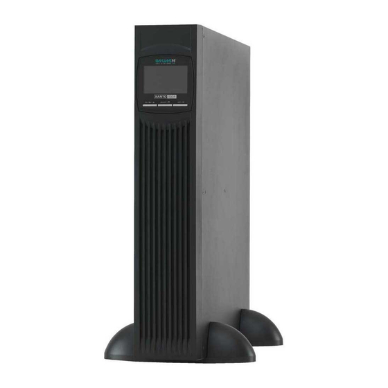
INTRODUCTION Slot for optional SNMP adapter or AS400-/ dry-contact inter- face-card Emergency-off function (EPO = Emergency Power Off) 2 years warranty including battery and 24 hours free exchange in advance Figure 1: XANTO 700 - 1500 Figure 2: XANTO 2000 - 3000 Figure 3: XANTO 700R - 3000R in the rack Figure 4: XANTO 700R –... -
Page 7: Safety Warnings
SAFETY WARNINGS 2. Safety warnings This manual contains important instructions that you must follow dur- ing the installation and maintenance of the UPS system and the bat- teries. Please read all the instructions in the manual before working with the device. Keep the manual in a safe place. CAUTION ... -
Page 8: Installation
INSTALLATION 3. Installation 3.1 Checking the delivery Keep the transport box and the packaging material for the carrier or sales point. If parts of the system have been damaged in transit, sub- mit a transport damage complaint to your supplier within 24 hours. If you only discover damage after accepting the device, please submit a complaint for concealed damage. -
Page 9: Checking The Accessories
INSTALLATION 3.3 Checking the accessories Description 19"mounting bracket (left and right) Feet for tower mounting (sets) Extension for feet for tower fitting USB interface cable 10A IEC extension cable 2 3 16A mainpower cable Battery cable Quick start guide DataWatch software* Manual* *Download from www.online-ups.com... -
Page 10: Figure 5: Removing The Frontpanel
INSTALLATION 1. Position the UPS system on an even, stable surface for its final location. 2. If you install additional battery packs, position them next to the UPS system. 3. In pure tower models (Art.-No. X700 – X3000) the battery is connect 4. -
Page 11: Installation In A Rack, Activating The Batteries
INSTALLATION Figure 7: Foot mounting Figure 8: Installation of the rack-tower-versa- tile model as a tower Connecting additional battery packs In order to install additional battery packs, remove the covers of the battery connector on the back of the UPS system and the battery packs, see Chap. -
Page 12: Figure 9: Removing The Frontpanel
INSTALLATION The casing is very heavy (see Chap. 8 Technical data). Optional slide rails (article no. Rack Kit) are available for the rack model. The slide rails fit 48 cm (19 inch) racks with a depth of 48 to 78 Fit the rack kit (separate assembly instructions provided with the rack kit). -
Page 13: Figure 11: Connecting The Battery
INSTALLATION Figure 11: Connecting the battery Figure 12: Mounting the frontpanel Finally, fit the front panel by reversing the sequence. Align the mounting bracket (L = left and R = right) with the screw holes on either side of the UPS system and affix it using the M4 x 8 countersunk screws provided (see Fehler! Verweisquelle konnte nicht gefunden werden.). -
Page 14: Getting Started
INSTALLATION DC Input” cover on the last battery pack. Keep the covers and the screws. 2. Connect all plug connections between the battery packs and the UPS system. This involves connecting the “VDC Output” output on a battery pack with the “VDC Input” on the upstream battery pack. - Page 15 INSTALLATION 5. The UPS system carries out a self-test, after which “OK” ap- pears on the display. The UPS system is now operating in nor- mal mode and supplying the load with reliable power. 6. If an additional emergency power off switch has been installed, the emergency stop function needs to be tested.
- Page 16 INSTALLATION 2. Disconnect the mains connection cable of the UPS system from the socket. The display on the UPS system goes out after a short time and the UPS system switches off completely. 16 / 56 X700-3000_usermanual_engl_20170405.docx...
-
Page 17: Operation
OPERATION 4. Operation 4.1 Control panel The UPS system has a control panel with three buttons and a graph- ical display (see Figure 15). Figure 15: Control panel and display Button Function In standby mode: Press button for Switch on more than 2 seconds In battery mode: Press button for more than 2 seconds, not valid if... -
Page 18: Table 2: Descriptions Of Display
OPERATION (switch to standby or bypass mode, depending on the menu setting) In configuration mode: Press the but- Selection ton to apply the selection In normal mode: Switching the dis- play from input voltage, frequency and current, battery voltage, current Switch over and capacity, UPS internal tempera- ture, output voltage, frequency and... -
Page 19: Display And Menu
OPERATION 4.2 Display and menu Symbol Description Function Pressing the SELECT button in normal mode displays the following measurements: Input, battery, Input voltage, frequency and current, battery temperature, out- voltage, capacity and current, UPS internal put, load temperature, output voltage, current and fre- quency, load in %. -
Page 20: Table 3: Display
OPERATION Symbol Description Function Output sockets Active UPS output Battery symbol in DC link: UPS system in bat- Battery tery mode Battery symbol in DC link: Battery in charging Battery charging mode Bypass mode, the load is supplied directly by Bypass mode the supply network without UPS protection High-efficiency... -
Page 21: Table 5: Overview Of Operating Status
OPERATION Battery Replace Bypass not within tolerance Charger Disable Remaining autonomy time EEPROM Error Enable EPO / Emergency Power Off Escape Bypass frequency not stable Battery not connected Battery overloaded Input voltage too high Overload Standby Shudown Site Fault Temperature Table 5: Overview of operating status 21 / 56 X700-3000_usermanual_engl_20170405.docx... -
Page 22: Settings
OPERATION 4.3 Settings 1. Open configuration menu: Switch to standby- or bypass mode and press button for 2 seconds. 2. Selection of menu options: Press button until you reach the menu option you want (see Table 6: Configuration menu). 3. Select menu option: Press OFF / button. - Page 23 OPERATION “DIS” Bypass mode: If the UPS system is switched off, it is switched to bypass instead of standby mode. [ENA] = Enabled [DIS] = Disabled “DIS” Battery deep discharge protection: Shutdown of all output sockets after time defined here. [0 –...
-
Page 24: Operating Statuses
OPERATION “999” Shutdown time for programmable output sockets: [0 - 999] = Shutdown of programmable output sockets in battery mode after time defined here. Only available if “Programmable output sockets = active” and UPS system re- started after setting the time. 2.36V / cell Charging voltage: Boost voltage [2.25 –... -
Page 25: Figure 17: Battery Mode Display
OPERATION In normal mode, “OK” is shown on the display and the UPS system is fed by the supply network. The UPS system monitors the batteries and charges them as required. The load connected is supplied with reliable UPS power. Battery mode In battery mode, the following display appears: Figure 17: Battery mode display... -
Page 26: Figure 18: Display In Standby Mode
OPERATION Figure 18: Display in standby mode No power is available for the load connected. The battery is charged if necessary. High-efficiency mode In high-efficiency mode, the load are supplied via the bypass. The in- verter is always ready for use at the same time. If the supply network is outside the tolerance, there is a smooth transition to normal mode. -
Page 27: Figure 20: Display In Bypass Mode
OPERATION Figure 20: Display in bypass mode Frequency converter mode In addition to regular UPS mode, the UPS system can also operate as a frequency converter. This involves providing the load with a constant output frequency of either 50 or 60Hz. Bypass is not available in fre- quency converter mode. -
Page 28: Communication And Interfaces
COMMUNICATION AND INTERFACES 5. Communication and interfaces 5.1 RS 232 and USB interface In order to establish communication between the UPS system and a computer, connect the computer using a suitable data cable (cable provided) to the RS-232 or USB interface on the UPS system (see Chap. -
Page 29: Slot For Interface Cards
COMMUNICATION AND INTERFACES 5.2 Slot for interface cards The XANTO features a slot (see Chap. 8.6 Rear view) for the following interface cards: Product no. Description SNMP adapter Basic DW7SNMP30 The SNMP adapter communicates via TCIP/IP with the load at- tached to the network. -
Page 30: Figure 23: Emergency Power Off Connector
COMMUNICATION AND INTERFACES CAUTION The emergency power off switch must not be connected to circuits which are connected to the supply network. Reinforced insulation from the network is required. The emergency power off switch must be designed for at least 60V DC / 30V AC and 20mA. -
Page 31: Surge Voltage Protection For Data And Telephone Lines (Dsl / Telephone / Fax / Network)
COMMUNICATION AND INTERFACES 5.4 Surge voltage protection for data and telephone lines (DSL / telephone / fax / network) The surge protection filters surge voltage from the data and telephone cables. This involves connecting the incoming cable to the IN connec- tion on the reverse of the UPS system. - Page 32 COMMUNICATION AND INTERFACES Changing the output voltage Enable / disable and configure converter mode Enable / disable high efficiency mode Enable / disable high bypass mode Configure and enable/disable the battery deep dis- charge protection Configure additional battery packs Select the type of autonomy time (accumulated, re- maining) Configure and enable/disable the emergency power off function (EPO)
- Page 33 COMMUNICATION AND INTERFACES Manual UPS fulltest Auto UPS selftest Enabe/disable alarm for battery operation Enable/disable all alarms Reset UPS system to factory settings Display alarm-, warning- and error-messages Chronological record, display and export (csv) of warning-, alarm- and error-messages Record, display and export (csv) of voltage, current, frequency and temperature (datalog chart) Customized event configuration 33 / 56...
-
Page 34: Maintenance
MAINTENANCE 6. Maintenance 6.1 Care and maintenance To ensure a long service life of the system, the area around the UPS system should be kept clean and free of dust. If the area around the system is very dusty, clean the external surfaces of the system with a vacuum cleaner. -
Page 35: Changing Batteries In Tower
MAINTENANCE 6.4 Changing batteries in tower PLEASE NOTE Do not replace the batteries while the UPS system is in battery mode. To replace the batteries, the UPS system must be switched off, dis- connected from the supply network and opened. Batteries cannot be hot-swapped. -
Page 36: Changing The Batteries In Rack
MAINTENANCE CAUTION DANGER OF ELECTRIC SHOCK. Never make changes to the battery cabling or connections. Attempting to change the battery cabling yourself could lead to serious injury. The batteries of the UPS system are very heavy. Be careful when handling heavy batteries. -
Page 37: Figure 24: Removing The Frontpanel
MAINTENANCE CAUTION Do not open or damage the battery or batteries. Battery acid can damage the eyes and skin and cause poisoning. DANGER OF ELECTRIC SHOCK. Never make changes to the battery cabling or connections. Attempting to change the battery cabling yourself could lead to serious injury. -
Page 38: Figure 25: Disconnect The Battery Connector
MAINTENANCE Figure 25: Disconnect the battery connector 3. Remove the battery cover (see Figure 26). Figure 26: Removing the battery cover 4. Carefully remove the battery insert using the handle. 5. Replace the batteries in the battery insert. PLEASE NOTE ... -
Page 39: Testing The New Batteries
MAINTENANCE CAUTION A small arc can occur when the batteries are connected to the UPS system. This is normal and represents no risk to person- nel. Insert the battery cable quickly and firmly into the battery plug connection in the UPS system. 7. - Page 40 MAINTENANCE CAUTION Do not open or damage the battery or batteries. Battery acid can damage the eyes and skin and cause poisoning. 40 / 56 X700-3000_usermanual_engl_20170405.docx...
-
Page 41: Troubleshooting
TROUBLESHOOTING 7. Troubleshooting The XANTO is designed for autonomous operation and automatically reports and problems in the display. 7.1 Error codes Error code Event Error starting the DC link DC link voltage too high DC link voltage too low Error starting inverter Inverter voltage too high Inverter voltage too low Short circuit in inverter output... -
Page 42: Troubleshooting
TROUBLESHOOTING Warning sound every 2 Battery overload seconds Warning sound every 2 UPS input error seconds Emergency power off Warning sound every 2 active seconds Warning sound every 2 Temperature too high seconds Warning sound every 2 Charger error seconds Warning sound every 2 Battery error seconds... - Page 43 TROUBLESHOOTING and start the UPS system using the ON button. L and N wrong way Rotate the mains plug symbols and round on UPS input. about 180 degrees. warning flash and an alarm is sounded every 2 seconds. The internal battery is not Check that the battery is connected.
-
Page 44: Muting The Alarm
The alarm cannot be muted for alarm and error messages. 7.5 Support ONLINE USV-Systeme AG (ONLINE) is one of the leading manufac- turers of uninterruptible power supplies (UPS). Since 1988, the Ger- man company has focussed on the development, production, sale and support of UPS systems. - Page 45 TROUBLESHOOTING Hardware hotline: +49 (89) 242 39 90 - 18 Free 24 h advance exchange Interactive UPS configurator online or as app 2 years full warranty, optional renewal Unbureaucratic 14 day money-back guarantee Excellent product availability and wide network of distributors. Further information: www.online-usv.de 45 / 56...
-
Page 46: Technical Data
190 x 335 x 415 20.3 kg XANTO 3000 190 x 335 x 415 28.5 kg XANTO 1000 / 1500 battery pack 158 x 238 x 397 19.8 kg XANTO 2000 battery pack 190 x 335 x 415 30.0 kg... -
Page 47: Electrical Connections
Input connection Output connections XANTO 700 4x IEC320 C13 (10A) IEC320 C14 (10A) XANTO 700R 8x IEC320 C13 (10A) XANTO 1000 4x IEC320 C13 (10A) IEC320 C14 (10A) XANTO 1000R 8x IEC320 C13 (10A) XANTO 1500 4x IEC320 C13 (10A) - Page 48 TECHNICAL DATA Input current 5.3A 7.7A 11.0A 15.3A 17.6A Output voltage, toler- ance in battery opera- 230V +/-1% tion Output frequency, nor- 50 / 60H +/-0,1Hz mal operation Output frequency, bat- 50 / 60H +/-3Hz tery operation Output voltage adjust- 208 / 220 / 230 / 240V able to Max.
-
Page 49: Batteries And Autonomy Time
UPS internal battery Battery pack Tower models XANTO 700 24V (2x 12V / 9Ah) XANTO 1000 36V (3x 12V / 9Ah) 36V (2x 3x 12V / 9Ah) XANTO 1500 36V (3x 12V / 9Ah) 36V (2x 3x 12V / 9Ah) -
Page 50: Rear View
TECHNICAL DATA XANTO 15 / 61 / 171 / 229 / 269 / 349 / 409 / 1500 / 52 XANTO 16 / 65 / 180 / 241 / 304 / 367 / 430 / 2000 / 52 XANTO 17 / 67 / 186 / 249 /... -
Page 51: Figure 28: Rear View Of Xanto 1000 - 1500
TECHNICAL DATA Figure 28: Rear view of XANTO 1000 - 1500 Figure 29: Rear view of XANTO 2000 51 / 56 X700-3000_usermanual_engl_20170405.docx... -
Page 52: Figure 30: Rear View Of Xanto 3000
TECHNICAL DATA Figure 30: Rear view of XANTO 3000 Figure 31: Rear view of XANTO 700R 52 / 56 X700-3000_usermanual_engl_20170405.docx... -
Page 53: Figure 32: Rear View Of Xanto 1000R - 1500R
TECHNICAL DATA Figure 32: Rear view of XANTO 1000R - 1500R Figure 33: Rear view of XANTO 2000R 53 / 56 X700-3000_usermanual_engl_20170405.docx... -
Page 54: Figure 34: Rear View Of Xanto 3000R
TECHNICAL DATA Figure 34: Rear view of XANTO 3000R 54 / 56 X700-3000_usermanual_engl_20170405.docx... -
Page 55: Ce Confirmation
TECHNICAL DATA 8.7 CE confirmation 55 / 56 X700-3000_usermanual_engl_20170405.docx... -
Page 56: Warranty
The content is copyright © 2017 by ONLINE USV-Systeme AG. All rights reserved. Unauthorised reproduction in part or in whole is not permitted without consent.
Need help?
Do you have a question about the XANTO 1000 and is the answer not in the manual?
Questions and answers