
Related Manuals for Entrematic Ditec HA7


Summary of Contents for Entrematic Ditec HA7
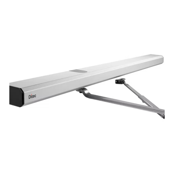
- Page 1 Installation and Service Manual Swing Door Operator Ditec HA7 Trusted brands. Great products.
- Page 2 Entrematic as word and logo are trademarks owned by the Entrematic Group © Entrematic, 2020 Technical data subject to change without notice.
-
Page 3: Table Of Contents
Safety precautions ..............................7 Electronic equipment reception interference ......................8 Environmental requirements ............................ 8 Technical specifications .......................... 9 Permitted door weight and door width for Ditec HA7 ................... 10 How the Ditec HA7 works ........................11 Control switch..............................11 5.1.1 HOLD/AUTO/OFF switch ........................... - Page 4 12.2 App ................................... 39 12.2.1 Install the app............................39 12.2.2 Log in to the app with owner ......................39 12.2.3 Learn ................................40 12.2.4 Test ....................................41 12.2.5 Settings .............................. 41 12.2.6 Add user ..............................42 12.2.7 Remove user ............................... 42 12.2.8 Log into the app with user ..........................
-
Page 5: Revision
1 Revision Revision Following pages have been revised: Page Revision 9,10 Changed weight notes 21, 25 Changed fastener specifications 39, 43 Changed app images Changed configuration parameters 1021444-2.0 Issue 2020-08-31... -
Page 6: Instructions For Safe Operation
2 Instructions for safe operation Instructions for safe operation • Failure to observe the information in this manual may result in personal injury or damage to equipment. • To reduce the risk of injury to persons - use this operator with single swinging only. -
Page 7: Important Information
Important information Intended use The Ditec HA7 is an automatic swing door operator developed to facilitate interior entrances to buildings and within buildings through swing doors. The Ditec HA7 is an electromechanical operator approved for fire door applications. It is to be installed indoors where it is suitable for almost all types of internal swing doors. -
Page 8: Electronic Equipment Reception Interference
Environmental requirements Entrematic products are equipped with electronics and may also be equipped with batteries containing materials which are hazardous to the environment. Disconnect power before removing electronics and battery and make sure it is disposed of properly according to local regulations (how and where) as was done with the packaging material. -
Page 9: Technical Specifications
Ensure that the door operator with technical specification below is suitable for the installation. Manufacturer: Entrematic Address: 221A Racco Parkway Vaughan Canada Type: Ditec HA7 Power supply: 120 V AC +10/-15%, 50/60 Hz, mains fuse max 10A (building installation) Power consumption: Max. 90 W Auxiliary voltage: 24 V DC, max. -
Page 10: Permitted Door Weight And Door Width For Ditec Ha7
4 Technical specifications This product is to be installed internally. Permitted door weight and door width for Ditec HA7: Push arm: 150 Lbs. / 48" or 266 Lbs. / 36" Pull arm: 112 Lbs. / 48" or 200 Lbs. / 36"... -
Page 11: How The Ditec Ha7 Works
How the Ditec HA7 works The swing door operator Ditec HA7 uses a motor which is connected to the output shaft. The push or pull arm system that is connected to the output shaft opens the door in a surface mounted application. -
Page 12: Closing
5 How the Ditec HA7 works 5.2.6 Closing When the hold open time has elapsed, the operator will close the door automatically, using spring force and motor. The door will slow to low speed at latch check before it reaches the fully closed position. -
Page 13: Part Identification
6 Part identification Part identification 1021444-2.0 Issue 2020-08-31... - Page 14 6 Part identification Item Art. No. Description W7-331020157 Ground wire W7-330000828 Back plate with power cable W7-331020445BK Spindle cover kit (Black) W7-331020445PD Spindle cover kit (Grey) W7-331019785 Bracket power plug W7-331020704BK Endplate with control switch (Black) W7-331020393BK Endplate (Black) W7-331018537 Control unit (CU) W7-330000841 Transmission unit kit...
-
Page 15: Arm Systems
7 Arm systems Arm systems Pushing installation with PUSH arm Reveal Part No.: 0 - 68mm (0 - 2 11/16") Part No.: 56 - 130mm (2 1/4 - 5 1/8") 7.1.1 Drive shaft extension kits for PUSH arm 3 / 8” 35mm 20mm 3 / 4”... -
Page 16: Pulling Installation With Pull Arm
7 Arm systems Pulling installation with PULL arm Part No.: W7-331020226BK 7.2.1 Drive shaft extension kits for PULL arm 43mm 3 / 4” 28mm 1 / 8” Part No.: H-W7-1020925 Issue 2020-08-31 1021444-2.0... -
Page 17: Options
8 Options Options Push plates For ADA compliance, center of push plate(s) must be 34"-48" above finished floor or height required by local AHJ. 8.1.1 Push plates PRESS TO OPEN P/N: W6-115 P/N: W6-124-1 PRESS TO OPEN P/N: W6-110 P/N: W6-110-2 P/N: W6-105 8.1.2 Remote transmitter push plates... -
Page 18: Labels
8 Options Labels PULL TO PUSH TO ACTIVATE ACTIVATE Push side “PUSH TO ACTIVATE” Pull side “PULL TO ACTIVATE” ACTIVATE SWITCH TO OPERATE Dual Side “Activate Switch to Operate” Dual Side “AUTOMATIC DOOR / CAUTION” ANNUAL COMPLIANCE INSPECTION Inspected for and complies with ANSI A156. -
Page 19: Pre-Installation
9 Pre-installation Pre-installation General tips/Safety concerns In all instances, where work is being done, the area is to be secured from pedestrian traffic, and the power removed to prevent injury. • Make sure that the power is off before installing. •... -
Page 20: Installation Examples
Brick wall from the underside * Entrematic minimum recommended requirements. Building Codes may give different specifications. ** Thinner wall profiles (3-5 mm) must be reinforced with rivet nuts. *** Thinner wall profiles (4-6 mm) must be reinforced with rivet nuts. -
Page 21: Mechanical Installation
10 Mechanical installation Mechanical installation The operator is mounted on either side of the door header depending on type of doors. The door is controlled with a push or pull arm system. Note! Consider all power wire entry locations and signaling wires before preparing back plate. 10.1 PUSH arm system 1. - Page 22 10 Mechanical installation Issue 2020-08-31 1021444-2.0...
- Page 23 10 Mechanical installation 1021444-2.0 Issue 2020-08-31...
- Page 24 10 Mechanical installation Issue 2020-08-31 1021444-2.0...
- Page 25 10 Mechanical installation 1021444-2.0 Issue 2020-08-31...
- Page 26 10 Mechanical installation Issue 2020-08-31 1021444-2.0...
- Page 27 10 Mechanical installation 1021444-2.0 Issue 2020-08-31...
-
Page 28: Pull Arm System
10 Mechanical installation 10.2 PULL arm system 1. Determine the Door Hand (pull instructions) Issue 2020-08-31 1021444-2.0... - Page 29 10 Mechanical installation 1021444-2.0 Issue 2020-08-31...
- Page 30 10 Mechanical installation Issue 2020-08-31 1021444-2.0...
- Page 31 10 Mechanical installation 1021444-2.0 Issue 2020-08-31...
- Page 32 10 Mechanical installation Issue 2020-08-31 1021444-2.0...
- Page 33 10 Mechanical installation 1021444-2.0 Issue 2020-08-31...
- Page 34 10 Mechanical installation Issue 2020-08-31 1021444-2.0...
-
Page 35: Electrical Connection
11 Electrical connection Electrical connection Note! The installation shall be made according to local codes. During any work with the electrical connections the mains must be disconnected. • Place the electric switch easily accessible from the operator. If a plug contact is used in the installation the wall socket shall be placed easily accessible from the operator. - Page 36 11 Electrical connection Alt. 2 a Disconnect the mains power. b Fix the adaptor in the box. c Disconnected the power wire (1) from the terminal (3), and protect the power with insulated tapes. d Connect the adaptor wire (2) to the terminal (3). e Connect mains power to the adaptor.
-
Page 37: Control Unit (Cu)
11 Electrical connection 11.2 Control unit (CU) 1021444-2.0 Issue 2020-08-31... -
Page 38: Start-Up
12 Start-up Start-up Note: An external door stop is to be installed to prevent the door from over travel. 12.1 Spring pre-tension The spring pre-tension is factory set to either size #2 PUSH / PULL or size #4 PUSH. Adjust the spring according to the following information. -
Page 39: App
Before the learning procedure starts, make sure that the door has been properly closed i.e., not by force. 12.2.1 Install the app Download the app Entrematic Swing Door Manager at App Store or Google Play. 12.2.2 Log in to the app with owner 1021444-2.0... -
Page 40: Learn
12 Start-up 12.2.3 Learn Connect mains power (the operator will find its closed position). Press Learn button for 4 seconds Scan QR code on product Note! If any of the parameters SPRING PRE-TENSION are changed after performing a learn, a new learn must be carried out. -
Page 41: Test
12 Start-up 12.2.4 Test 12.2.5 Settings 1021444-2.0 Issue 2020-08-31... -
Page 42: Add User
12 Start-up 12.2.6 Add user 12.2.7 Remove user Issue 2020-08-31 1021444-2.0... -
Page 43: Log Into The App With User
12 Start-up 12.2.8 Log into app with user At the same time, owner should select “Add user” and show the QR code. User scan the QR code from owner 1021444-2.0 Issue 2020-08-31... -
Page 44: Configuration Parameters
12 Start-up 12.2.9 Configuration parameters Parameter name Default settings Value Hold open time 2s- 6h Opening time 4.5s 4.5s - 9s Closing time 4.5s 4.5s - 9s Arm system Push Push / Pull Push and go Not active Not active / Active Power assist Off / Low / Medium / High Extend closing torque... -
Page 45: Cover
13 Cover Cover • Secure cover with screw. • Apply the Ditec/Entrematic logotype to the cover, see below. • Apply the labels to the underside of the cover, see below. Ditec ENTREMATIC 1021444-2.0 Issue 2020-08-31... -
Page 46: Troubleshooting
14 Troubleshooting Troubleshooting Fault Possible reasons why Remedies/Explanations The door does not open Control switch or is set to OFF Change the setting of the control switch The motor does not start Mains power is missing Check the mains power and fuse in the building The motor starts but the Mechanical lock is locked Unlock the lock... -
Page 47: Ansi / Bhma A156.19 (Low Energy Application)
15 ANSI / BHMA A156.19 (LOW ENERGY APPLICATION) ANSI / BHMA A156.19 (LOW ENERGY APPLICATION) 15.1 REQUIREMENTS FOR POWER OPERATED DOORS The following texts are excerpts from American National Standard for power-operated doors. Please refer to the full standard if necessary. 15.1.1 Activation The operator shall be activated by a knowing act. -
Page 48: Signage
15 ANSI / BHMA A156.19 (LOW ENERGY APPLICATION) Table II Total Opening Time to 90 Degrees Backcheck at 60 degrees Backcheck at 70 degrees Backcheck at 80 degrees Table I plus 2 seconds Table I plus 1.5 seconds Table I plus 1second If the door opens more than 90 degrees, it shall continue at the same rate as backcheck speed. - Page 50 • ditecentrematic.ca Entrematic Canada Inc. Entrematic USA Inc. Toll Free: 1-877-348-6837 Toll Free: 1-866-901-4284 Email: info.ditec.ca@Entrematic.com Email: info.ditec.us@Entrematic.com Web: www.ditecentrematic.ca Web: www.ditecentrematic.us...
Need help?
Do you have a question about the Ditec HA7 and is the answer not in the manual?
Questions and answers