Advertisement
Quick Links
General Instructions
01PTSHPWOR1010DDOW-V4
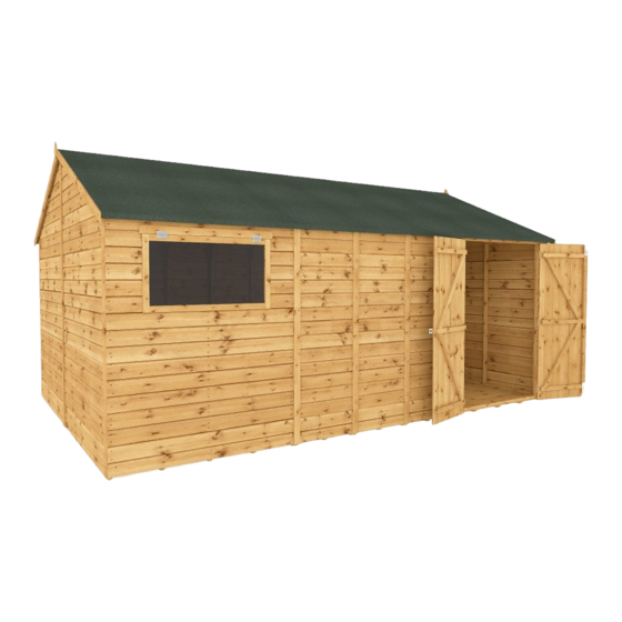
Modular Workshop 10x10, 12x10, 16x10 & 20x10
BEFORE YOU START PLEASE READ INSTRUCTIONS CAREFULLY
- Check the pack and make sure you have all the parts listed.
- When you are ready to start, make sure you have the right tools at hand (not supplied)
including a Phillips screwdriver, Stanley knife, Wood saw, Step ladder, Hammer and a
Drill with 2mm bit.
- Ensure there is plenty of space and a clean dry area for assembly.
TIMBER
As with all natural materials, timber can be a ected during various weather conditions.
For the duration of heavy or extended periods of rain, swelling of the wood panels may
occur. Warping of the wood may also occur during excessive dry spells due to an interior
moisture loss. Unfortunately, these processes cannot be avoided but can be helped. It is
suggested that the outdoor building is sprayed with water during extended periods of
warm sunshine and sheltered as much as possible during rain or snow.
Once your garden building has been installed it will need to be treated as soon as
possible and annually to prevent the timber from deteriorating and to waterproof it.
This is required to maintain the anti-rot guarantee.
Dip Treated buildings - Require a preservative treatment to protect against rot and
decay and a waterproof treatment to prevent water ingress
Pressure Treated buildings - Require a waterproof treatment to prevent water ingress
Log Cabins - Are supplied untreated and require a preservative and waterproo ng
treatment.
BUILDING A BASE
When thinking about where the building and base is going to be constructed:
Ensure that there will be access to all sides for maintenance work and annual
treatment.
Ensure the base is level and is built on rm ground, to prevent distortion. Refer to
diagrams for the base dimensions, The base should be slightly smaller than the external
measurement of the building, i.e. The cladding should overlap the base, creating a run
o for water. It is also recommended that the oor be at least 25mm above the
surrounding ground level to avoid ooding.
TYPES OF BASE
- Concrete 75mm laid on top of 75mm hard-core.
- Slabs laid on 50mm of sharp sand.
Whilst all products manufactured are made to the highest standards of Safety and in
the case of childrens products independently tested to EN71 level, we cannot accept
responsibility for your safety whilst erecting or using this product.
Please retain product label and instructions for future reference
x2
All buildings should be
erected by two adults
For ease of assembly, you
MUST pilot drill all screw
holes and ensure all screw
heads are countersunk.
2mm Drill bit
For ease of assembly, you
will need a tape measure to
check dimensions of
components.
Pressure Treated Timber
Pressure treating is a chemical process which helps to protect wood against adverse weather which could
lead to rot or insect damage.
The most common chemicals used to pressure treat wood are Alkaline Copper Quaternary (ACQ),
Copper Azole (CA), and Micronized Copper Quaternary (MCQ).
Safety: Always wear gloves, eye protection and a dust mask when handling wood. Due to chemicals in
pressure treated wood, never burn its sawdust or scraps; instead dispose in a land ll.
For assistance please contact customer care on: 01636 821215
Mercia Garden Products Limited,
Sutton On Trent,
Newark,
Nottinghamshire,
NG23 6QN
www.merciagardenproducts.co.uk
Winter = High Moisture = Expansion
Summer = Low Moisture = Contraction
CAUTION
Every e ort has been made during the
manufacturing process to eliminate the
prospect of splinters on rough surfaces of the
timber. You are strongly advised to wear gloves
when working with or handling rough sawn
timber.
Screws & Nails
Bolts
To identify the
xings required
Measure
Measure
for each step use a
overall
under the
length
measuring tape.
head
P 1
Advertisement

Related Manuals for Mercia Garden Products 01PTSHPWOR1010DDOW-V4


Summary of Contents for Mercia Garden Products 01PTSHPWOR1010DDOW-V4
- Page 1 It is also recommended that the oor be at least 25mm above the surrounding ground level to avoid ooding. For assistance please contact customer care on: 01636 821215 TYPES OF BASE Mercia Garden Products Limited, Sutton On Trent, Newark, - Concrete 75mm laid on top of 75mm hard-core.
- Page 2 01PTSHPWOR1010DDOW-V4 The building you have purchased can be built in two ways as an Apex or a Reverse Apex. Within this document there are seperate instructions to show how to install each style please refer to the corresponding pages for the style you have chosen.
- Page 3 01SHPWOR1010DDOW-V4 Please retain product label and instructions for future reference Building content - Pack A 01PTSHPWOR1010DDOW-V4 Hasp and Staple Lock Butt Hinge - Qty 4 PI-07-0191 PI-07-0066 Tower Bolt - Qty 2 PI-07-0030 Felt Window Side Panel Plain Side Panel...
- Page 4 Please retain product label and instructions for future reference Building content - Pack B Building content - Pack C Building content - Pack D 01SHPWORPB-V1 01SHPWORPC-V1 01SHPWORPD-V1 Plain Side Panel 2ft Floor 2ft Roof Window Side Panel Plain Side Panel 5ft Floor Panel Single Door Panel Plain Side Panel...
-
Page 5: Pre-Assembly
Please retain product label and instructions for future reference Apex Installation Step 2 Repeat the previous step when adding the second Small Plain Panel (No. 6), ensure Pre Assembly they are level at the top and bottom then x together using 7x50mm screws. Remove transportation Stagger the screws so they do not collide. - Page 6 Please retain product label and instructions for future reference Please retain product label and instructions for future reference Step 4 Step 6 Place the newly assembled Gables above Place the other set of assembled Gables the assembled panels. Make sure that the (No.
- Page 7 Please retain product label and instructions for future reference Step 8 Step 7 Place the oors (No. 7, 35 & 37) on a rm Fix the corners of the assembled and level base, ensure the base has suitable plain gable and a plain side panel drainage free from areas where water can (No.
- Page 8 Please retain product label and instructions for future reference Step 10 Step 11 10X10 Build up the walls of your building Fix the Door Gable (refer to steps 1, using the plain side panels (No. 2 & 2 and 3 if you have not already 10X10 34), the window sides (No.
- Page 9 Please retain product label and instructions for future reference Step 12 Step 14 Fix the T Hinges (No. 31) onto the doors (No. Place an assembled Truss central to 9) as shown using 7 x 30mm screws per T where two panels join. Align the hinge.
- Page 10 Please retain product label and instructions for future reference Step 15 Step 16 Secure the roof panels (No. 8, 36 & Following the same method used 38) together using the metal U in the previous step, secure the channel (No. 32) and 6x40mm roof panels (No.
- Page 11 Please retain product label and instructions for future reference Step 17 Step 18 Once the roof is xed Cut four strips of felt (No. 29) 10X10 attatch the building to the and place onto the roof. See oor with 50 mm screws. below for sizes.
- Page 12 Please retain product label and instructions for future reference Step 19 Step 20 Attach the Fascia Spacing Fit the Cover Strips (No. 15 & 19) lock (No. 21) to the front to the building and secure in 10X10 and back of the roof using place with 40mm screws as 2x30mm screws per block.
- Page 13 Please retain product label and instructions for future reference Step 21 Step 23 Place the Door Cloaking Strip *SCREW COUNT PER WINDOW (No. 20) to the rear of one of the double doors. Fix in position 30mm Place the Window Strip (No. 18) screw screwing through the door into 11mm above the window gap in the...
- Page 14 Please retain product label and instructions for future reference Step 24 To x the Hasl and Staple Lock (No. 23) in place. Screw the Staple to the left hand door. Making sure the Hasp is in line with AFTER TREATMENT: the staple and screw into the right hand score around protective cover on glazing and...
- Page 15 Please retain product label and instructions for future reference Reverse Apex Installation Step 2 Repeat the previous step when adding the Pre Assembly second Small Plain Panel (No. 6), ensure they are level at the top and bottom then x Remove transportation together using 7x50mm screws.
- Page 16 Please retain product label and instructions for future reference Step 4 Step 6 Place the newly assembled Gables above Place the other set of assembled Gables the assembled panels. Make sure that the (No. 3 & 4) above the plain panels. Gables meet exactly in the middle and over hang from the sides equally at approx Make sure that the Gables meet exactly in...
- Page 17 Please retain product label and instructions for future reference Step 8 Step 7 Place the oors (No. 7, 35 & 37) on a rm Fix the corners of the assembled and level base, ensure the base has suitable plain gable and a plain side panel drainage free from areas where water can (No.
- Page 18 Please retain product label and instructions for future reference Step 10 Step 11 10X10 Build up the walls of your building Fix the Window Gable (refer to steps using the plain side panels (No. 2 & 1, 2 and 3 if you have not already 10X10 34), the double door panel (No.
- Page 19 Please retain product label and instructions for future reference Step 12 Step 14 Fix the T Hinges (No. 31) onto the doors (No. Place an assembled Truss central to 9) as shown using 7 x 30mm screws per T where two panels join. Align the hinge.
- Page 20 Please retain product label and instructions for future reference Step 16 Step 15 Following the same method used Secure the roof panels (No. 8, 36 & in the previous step, secure the 38) together using the metal U roof panels (No. 8, 36 & 38) channel (No.
- Page 21 Please retain product label and instructions for future reference Step 17 Step 18 Once the roof is xed Cut four strips of felt (No. 29) 10X10 attatch the building to the and place onto the roof. See oor with 50 mm screws. below for sizes.
- Page 22 Please retain product label and instructions for future reference Step 19 Step 20 Attach the Fascia Spacing Fit the Cover Strips (No. 15 & 19) lock (No. 21) to the front to the building and secure in 10X10 and back of the roof using place with 40mm screws as 2x30mm screws per block.
- Page 23 Please retain product label and instructions for future reference Step 21 Step 23 Place the Door Cloaking Strip *SCREW COUNT PER WINDOW (No. 20) to the rear of one of the double doors. Fix in position 30mm Place the Window Strip (No. 18) screw screwing through the door into 11mm above the window gap in the...
- Page 24 Please retain product label and instructions for future reference Step 24 To x the Hasl and Staple Lock (No. 23) in place. Screw the Staple to the left hand door. AFTER TREATMENT: Making sure the Hasp is in line with score around protective the staple and screw into the right hand cover on glazing and...
Need help?
Do you have a question about the 01PTSHPWOR1010DDOW-V4 and is the answer not in the manual?
Questions and answers