Table of Contents
Advertisement
Quick Links
Advertisement
Table of Contents

Subscribe to Our Youtube Channel
Related Manuals for TECO T-Verter E2 Series


Summary of Contents for TECO T-Verter E2 Series
- Page 1 E2 Adjustable Speed Driver Microprocessor Controlled IGBT Drive Inverter Motor Speed Regulator Operating Manual High Performance Adjustable Speed Micro Drives E2 Series 110V 0.2~0.75KW ( 0.53~1.6KVA ) 220V 0.2~2.2KW ( 0.53~4.0KVA ) 440V 0.75~2.2KW ( 1.7~4.0KVA )
- Page 2 Operations Manual Table of Contents Foreword ..................1 Chapter 1 Safety Precautions Operation Precautions..........3 2. Environmental Precautions ........6 Chapter 2 Hardware Instruction and Installation 1. Operational Environment.........7 2. Sample Model No. Identification......8 3. Specifications ............9 4. Wiring ..............15 5. Dimensions & Location of terminal block ....18 Chapter 3 Software Index 1.
- Page 3 Should there be any problem in using the product that can not be solved with the information provided in the manual, contact your nearest TECO distributor or sales representative who will be willing to help you.
- Page 4 Product Inspection TECO’s inverters have all passed the function test before delivery. Please check the following when you receive and unpack the inverter: The model and capacity of the inverter is the same as those specified on your order. Is there any damage caused by transportation. If so, do not apply the power.
- Page 5 Chapter 1 Safety Precautions 1. Operation Precautions 1.1 Before Power Up Danger Make sure the main circuit connections are correct. L1(L), L2, and L3(N) are power-input terminals and must not be confused with T1, T2 and T3. Otherwise, inverter damage can result.
- Page 6 1.2 When power is applied WARNING Do not attempt to install or remove input or output connectors of inverter when the power supply is turned on. Otherwise, the inverter may be damaged due to the surge peak caused by the insertion or removal of power. When momentary power loss is longer than 2 seconds (the large of horse power, the longer of time), the inverter does not have enough storage power to control the circuit;...
- Page 7 1.3 During operation Danger Do not connect or disconnect the motor while inverter is operating the motor. The inverter and the disconnect device can sustain damage from high levels of switch-off current transients. Danger To avoid electric shock, do not take the front cover off while power is on. The motor will restart automatically after stop when auto-restart function is enabled.
- Page 8 2. Precautions of operation environment Avoid any direct sunlight Keep away from Keep away from oil corrosive gas or liquid grease and gas Keep away from rain or Avoid metal dust and Keep away from salty where dripping water may dusty environments environments get into the inverter...
- Page 9 Chapter 2: Hardware Instructions and Installation 1. Operational Environment The installation site of the inverter is very important. It relates directly to the functionality and the life span of your inverter. Please carefully choose the installation site to meet the following requirements: Mount the unit vertically Environment temperature: -10...
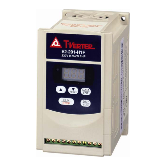
- Page 10 Ventilation & Installation Direction Front View Note: Maximum temperature in the enclosure 50 ℃ 2. Sample Model No. Identification Inverter Model MODEL: E2-201-M1F Input Power Rating I/P: AC 1PH 200 ~ 240V 50/60 Hz Output Rating O/P: AC 3PH 0 ~ 240V 1 Hp 4.2 Amps E2 - Series Power...
- Page 11 3.Specification: Basic specification: Model : E2- 1P5-H1x 1P2-H1x Suitable Motor Power Rating (KW) 0.75 0.25 Motor (HP) Output Current (A) Rated Capacity (KVA) 0.53 0.88 Weight (Kg ) 0.72 Input Voltage Max. Single phase 100-120V (+10%, -15%), 50 / 60Hz (+/-5%) Output Voltage Max.
- Page 12 Functional specification: Item Specification Input Signal Type PNP type (SOURCE) input (External 24VDC Input is allowed) Control Method Sinusoidal wave PWM control Freq. Range 1~200 Hz*1 Resolution Setting Digital: 0.1 Hz (1 ~ 99.9 Hz); 1 Hz (100 ~ 200 Hz) Analog: 1Hz/ 60 Hz Freq.
- Page 13 Suitable optional and Wiring Specification Molded-Case Circuit Breaker / Magnetic Contact Warrantee does not apply to damage caused by the following situations: (1) Damage to the inverter caused by the lack of appropriate molded-case circuit breaker or when a circuit breaker with too large of capacity is installed between the power supply and the inverter.
- Page 14 Application and precautions of Peripherals Power supply: Make sure the correct voltage is applied to avoid damaging Power inverter. A molded-case circuit breaker or fused disconnect must be installed between the AC source and the inverter. Molded-case Molded-case circuit breaker: circuit breaker Use a molded-case circuit breaker that conforms to the rated Fuse...
- Page 15 External wiring should be carried out in accordance with following requirement. Check and reassure the wiring is correct after the wiring is complete. (Do not utilize the control circuitry buzzer to check the wiring.) EMI connections: It is very important that the connections between the inverter, the shielded motor cable, and the EMI filters are tested as follows.
- Page 16 Class A: P owe r Su pply P owe r Drive S yst em (P DS ) Main Trans former Me tal plate or pa nel D rive Powe r Port MCCB 3 ΦIM Re mo te con trol switche s, relay or simila r e quipm en ts When the distance between the inverter and motor is longer than 100 meters, cable wire should be carefully chosen to reduce the wiring resistance below 3% and the voltage drop (V) = √3 x Wire...
- Page 17 (a) good (b) good (c) not good (D) Wire specification, apply appropriate wire with correct diameter for primary power circuitry and control circuitry in accordance with electricity regulations. Wiring Diagram *( note)Braking Resister ( Option) L1 ( L) (U)T1 AC Input (V)T2 L3 ( N) (W) T3...
- Page 18 (External 24V supply) –...
- Page 19 Inverter terminal descriptions Primary Circuitry Terminal Block (TM1) descriptions Terminal Symbol Function Description L1(R) Primary power source input to Drive L2 (S) Single phase: L1/L2(1P2~201) or L/N; Three phase: L1/L2/L3 L3 (T) Extermal braking resistor terminal (Only for E2-202/203/401/402/403) T1 (U) Inverter output to Motor T2 (V) T3 (W)
- Page 20 SW1 function description SWITCH 1 External signal type 0~20mA analog signal (When F_11 is set to 1) 4~20mA analog signal (When F_11 is set to 2) 0~10 VDC analog signal (When F_11 is set to 1) Dimensions & Location of terminal block E2-1P2/1P5/101/2P2/2P5/201: See NOTE Unit: mm...
- Page 21 E2-202/203/401/402/403: See NOTE of Page 18 Unit: mm LENGTH MODEL E2-202/203/401/402/403 143.1 127.5 LENGTH MODEL E2-202/203/401/402/403 171.7 Dimensions & Installation of class B Filter M 4 x 1 4 L Φ 4 . 5 T Y P 6 0 .0 7 6 .0 2 5 .0...
- Page 22 Inverter with class B filter mounted. Inverter with class B filter & Din rail mounted kit. Mounting Instructions...
- Page 23 Din Rail Mounting Diagram Step1- Aim and insert the 4 retention ribs of the Step1- DIN Rail at the 4 Use a small holes in rear panel screwdriver Inserting hole of inverter inserting it into the middle rib middle rib of DIN Step2- Rail and press the Push the DIN Rail...
- Page 24 E2-1P2/1P5/101/2P2/2P5/201- N4X (IP65)TYPE: DATA RESET STOP 123.4/ 4.86 140.6/ 5.54 140.6/ 5.54 UNIT : mm/inch...
- Page 25 E2-202/203/401/402/403-N4X(IP65)TYPE: UNIT:mm/inch...
- Page 26 E2-1P2/1P5/101/2P2/2P5/201- - N4X(IP65)TYPE INSTALLATION : Potentiometer REV-0-FWD DATA RESET SWITCH STOP POWER SWITCH 123.4 mm NOTE : L1 L2 1. POWER SWITCH , REV-0-FWD SWITCH AND 100~120V Potentiometer are only for E2-1P2~201- N4S TYPE 200-240V 50/60 Hz 2. Power supply cable : #14 AGE (2.0mm² ) 3 Phases Single Phases 3.
- Page 27 E2-1P2~201- -N4 (WITHOUT SWITCH TYPE ) CONNECTIONS & EMC MOUNTING: EMC MOUNTIING 200mm Cutting Length of cable shield Power supply cable L1,L2, Motor cable ,T1,T2,T3 Length: Max 2M Note: TM2 Remote control Cable shielding cable should be connect connected to to ground screw ground clamp...
- Page 28 E2-1P2~201- -N4S (WITH SWITCH TYPE ) EMC MOUNTING & CONNECTIONS : CONNECTIONS 4 x Outer cover screw Power supply cable L1,L2, Motor cable ,T1,T2,T3 Power supply cable Motor cable Plug-in terminals EMC MOUNTIING 200mm Cutting Length of cable shield Power supply cable L1,L2, Motor cable...
- Page 29 E2-202/203/401/402/403—N4X(IP65)TYPE INSTALLATION: DATA RESET STOP POWER SWITCH Potentiometer REV-0-FWD SWITCH 210.0mm L1(L) L2(N) L3 2.Power supply cable : 4. Torque value of Screw : 220-240V 380-480V T1 T2 T3 E2-200 #12AWG(3.5mm²) (1).Power/Motor cable(TM1, Single/ThreePhases E2-400 #16AWG(1.25mm²) TM3) 3 Phases 3. Motor cable : Terminal : 8 kgf-cm(6.94 in-lb) E2-200 #14AWG(2.0mm²) (2).Remote control wire :...
- Page 30 E2-202/203/401/402/403—N4S (WITH SWITCH TYPE) CONNECTIONS&EMC MOUNTING: CONNECTION MOUNTING NOTE: For ALL FILTER MODELS, additional items will be find inside the box including : [1]pc of EMC conformed waterproof (IP65) ferrite core; [1]pc of metal fastener; [1]pc of MF Zin 5-C screw. "CAUTION: , if application use require to meet EMC regulation, you MUST first constrain the motor cables, close the ferrite core onto the motor cable outside the plastic enclosure as stated in the above diagram.
- Page 31 E2-202/203/401/402/403—N4 (WITHOUT SWITCH TYPE) CONNECTIONS&EMC MOUNTING: CONNECTION MOUNTING NOTE: For ALL FILTER MODELS, additional items will be find inside the box including: [1] pcs of EMC conformed waterproof (IP65) ferrite core; [1]pcs of metal fastener; [1]pcs of MF Zin 5-C screw. "CAUTION: if application use requires meeting EMC regulation, you MUST first constrain the motor cables, close the ferrite core onto the motor cable outside the plastic enclosure as stated in the above diagram.
- Page 32 Chapter 3 Software Index Keypad operating instructions Keypad Description POWER LED DATA ▼ ▲ RESET STOP CAUTION Do not operate keypad by screwdriver or other sharp-ended tool to avoid damaging keypad. Brief keypad operation flowchart ▲ ▼ (FREQ) * 1 (FREQ) (READ) ▲...
- Page 33 Parameter List Factory Function Function Description Page Note Unit Range setting Factory Adjustment Accel. Time Accel. time 0.1Sec 0.1 ~ 999 S *1 *3 Decel. Time Decel. time 0.1Sec 0.1 ~ 999 S *1 *3 0: Forward / Stop, Reverse / Stop Operation mode 0 ~ 1 1:Run/Stop, Forward / Reverse...
- Page 34 Factory Page Note Function Description Unit Range Function setting 0: REV run Reverse Lock-Out 0 ~ 1 1: REV run Lock-Out 0: enabled Momentary power 0 ~ 1 loss 1: disabled Auto restart Number of Auto-restart times 0 ~ 5 010: Constants initialization to 50Hz system Factory setting 020: Constants initialization to 60Hz system...
- Page 35 F_03: Operation mode selection = 0: Forward / Stop, Reverse / Stop 1: Run / Stop, Forward / Reverse NOTE 1: F_03 takes effect only when F_10 = 1 (external operation control) F_03 = 0 3 FWD /Stop 3 Run / Stop F_03 = 1 control 4 REV /Stop...
- Page 36 F_05: V/F pattern setting = 1 ~ 6 Selecting F_05 = 1-6 to select one of the six preset V/F patterns. (Refer to the following tables) Specification 50 Hz System Application General Application High starting torque Decreasing torque V (%) V (%) V (%) V/F pattern...
- Page 37 F_06: frequency upper limit range=1~120Hz F_07: frequency lower limit range=1~120Hz (1~200Hz with CPU versionv1.9 and above) F_06: Factory setting refers to F_25. Internal frequency F_06 (freq. Upper limit) signal F_07 (freq. Lower limit) (NOTE) Frequency setting signal NOTE: If F_07 = 0 Hz, If the frequency instruction is equal to 0Hz, the inverter will stop at 0 speed.
- Page 38 F_11: Speed Control = 0: Keypad = 1: Analog Speed Pot Terminal (TM2) (0 ~ 10V / 0-20mA) = 2: Analog Speed Pot Terminal (TM2) ( 4-20mA ) NOTE 1: When jog frequency or Sp1 frequency is F_06 switched on, the frequency is setup by Sp1 speed, the ▲▼...
- Page 39 Voltage 100% F_13= 50/60 2.5/3.0 NOTE: When F_13 = 0, the torque boost function is disabled. F_14 Stopping method = 0 : Controlled deceleration stop = 1 : free run to stop F_15 DC braking time = 0 ~ 25.5 sec F_16 DC braking starting frequency = 1 ~ 10 Hz F_17 DC braking level = 0 ~ 20 %...
- Page 40 F_18: Motor rated current = 50~100 %(0~200%: CPU version v1.9 and above) 1. The electronic thermal overload protection for motor: (1) Motor rated current = Inverter rated current x F_18 F_18 = Motor rated current / inverter rated current (2) When the load is within 100% of the motors rated current, the operation continues. When the load reaches 150% of the motors rated current the operation is allowed to continue for 1 minute.
- Page 41 F_19: Multifunctional input terminal 1 function = 1~ 5(1~6:CPU version v1.9 and above) F_20: Multifunctional input terminal 2 function = 1~ 5(1~6:CPU version v1.9 and above) F_19=1 or F_20 =1: JOG control (refer to F_09) F_19, F_20 =2 or 6 Multi-speed control: F_19=2 &...
- Page 42 Time Run/Stop F_20=4 5. F_19, F_20 = 5: Auto Reset when inverter faults. F_21: Multi-function output terminal control = 1 ~ 3 1. F_21 = 1: Run mode signal 2. F_22 = 2: At Frequency Speed Signal 3. F_21 = 3: Fault signal Terminal1 and2 of TM2 are activated at CPF, OL1, OL2, OCS, OCA, OCC, Ocd , Ocb , OVC , LVC , OHC.
- Page 43 F_23: Auto-restart after momentary power loss =0: auto-restart enabled =1: auto-restart disabled 1. When the AC power supply is temporary below low voltage protection levels because of power company issues or encountering large current loading in the same power supply system, the inverter will stop its output immediately.
- Page 44 4. If either of following situations should develop, the auto restart times will be reset: No additional malfunction (in operation or stop) occurs within 10 minutes. Press RESET button. F_25: Return to Factory Pre-Settings = 010: Constants initialization to 50Hz system = 020: Constants initialization to 60Hz system 1.
- Page 45 F_29: CPU program version F_30: Last three faults 1. Last three faults: indicate the sequence of the occurrence of malfunctions by the location of decimal point. x.xx indicates a recently happened malfunction. xx.x indicates the last malfunction that happened. xxx. Indicates the earliest malfunction in the record. 2.
- Page 46 Malfunction Indications and Countermeasures 1. Manual reset inoperative malfunctions INDICATION CONTENT POSSIBLE CAUSE COUNTERMEASURE Place a RC surge absorber in Program error Outside noise interference parallel with the noise generating magnetic contact EEPROM error EEPROM defective Replace EEPROM 1. Power source voltage too 1.
- Page 47 3.Manual Reset and Auto-Reset Operative Malfunction INDICATION CONTENT POSSIBLE CAUSE COUNTERMEASURE 1. Motor coil short-circuit with external casing Transient 1. Examining motor 2. Motor connection wire over-current 2. Examining wiring short-circuit with grounding starting machine 3. Replace transistor module 3. Transistor module damaged 1.
- Page 48 Special Condition Description INDICATION CONTENT DESCRIPTION When F_11 = 0, F_7= 0 and frequency setting < 1 Hz Zero Speed When F_11 = 1, F_7<(F_6/100), and frequency setting Stopping <(F_6/100) 1. If the inverter is set to external operation (F_10 = 1) and direct start is disabled (F_28 =1), the inverter cannot be Fail to start started and will flash SP1 when operation switch turned to...
- Page 49 General Malfunction Examination Method ABNORMALITY CHECK POINT COUNTERMEASURE Check if the power source on. Is the power source voltage delivered to Turn power source OFF and then ON L1, L2 terminal (is the charging indicator again. illuminated)? Reconfirm the power voltage level. Is there voltage output from output Turn power source OFF and then ON Motor...
- Page 50 Chapter 4: Troubleshooting Procedures Inverter Malfunction Clearly defined m alfunction Exam ining com ponent with Sign of burn Any sign of burnt sign of burnt or breakage or breakage of breakage? Indication of ABNORMAL Is the prim ary Replace DM abnorm ality circuitry DM norm al? Proceed exam ination...
- Page 51 ( Continued ) Examining Inverter parameters Carry out parameter initialization Designate operation control method Frequency instruction setting Does the controller displays Replace control board frequency setting? Is there voltage output on Replace control board UVW terminals? No, The problem Is replacing is not corrected Connect to motor and control board correct...
- Page 52 Error handling of malfunction indication of OC.OL When inverter display malfunction indication OC.OL. Is the primary ABNORMAL Replace I.G.B.T. circuit I.G.B.T. normal? NORMAL Is the appearance Replace defective PCB normal? Switch ON power supply Is there any malfunction indication Is the current ABNORMAL Input operation detector normal?
- Page 53 Error handling of malfunction indication of OV.LV Inverter display OV.LV Is there any abnormal breakage Replace defective board on appearance Switch ON power supply Is there any Replace control board malfunction indication Input operation instruction Input frequency instruction Is the output Replace control board frequency of controller displayed...
- Page 54 (1). Motor inoperative Is the circui t breaker (MCCB) switched ON? Can not Wiring short-circuit Can you switch ON the MCCB? Is the • Power source voltage between ABNORMAL abnormality L1-L2 power input terminals normal? • Poor wiring Normal (within +/- 10% of nominal value) E2 malfunction Is Power LED off ? Place the operation...
- Page 55 (2). Motor over-heat Reduce loading there over-loading Enlarge E2 and condition or the load current exceeds rated Motor capacity current? Operate at low Select another motor speed for a long time? Is the voltage level between E2 malfunction T1-T2, T2-T3, and T3-T1 normal? Is there anything that might...
- Page 56 (3). Disturbing motor operation Is the Increase or decrease appropriate acceleration/ During acceleration or acceleration / deceleration time setting deceleration ? deceleration time appropriate? Appropriate Reduce load Increase E2 and motor capacity Is the voltage level E2 malfunction between T1-T2, T2-T3, and T3-T1 normal? YES (The differences between different wires are within ±...
- Page 57 Routine examination and periodical examination Inverter requires routine and periodical examination and maintenance Carry out the examination only after the “ Power LED ” indicator goes off for at least 5 minutes Examination Maintenance Maintenance period Examination Criterion Countermeasure item description method Routine...
- Page 58 Maintenance and Examination Frequent examination and maintenance is not required for the inverter. To maintain appropriate reliability, please proceed with following periodical examination. Remember to turn off power supply and wait till the Power LED goes off before proceed. (Due to the large amount of remaining charges in the internal capacitors.) Clean out internal dust and dirt.
- Page 59 Voltage Current Measurement The voltage and current measurement on the primary and secondary side of the inverter may be different due to instrumentation variations. Refer to following diagram for measurement: Signal-phase power supply To motor Different kinds of instrument NOTE Measurement Measuring point Instrument...
- Page 60 EMI Filter (class B) Specification Model Dimension (mm) Current (A) Inverter model E2-2P2-M1F/E2-2P2-H1F E2F-2102 156 X 76 X 25 E2-2P5-M1F/E2-2P5-H1F E2-201-M1F/E2-201-H1F E2-202-H1F E2F-2202 172 X 120.2 X 38 E2-203-H1F E2-401-H3F E2F-4103 172 X 120.2 X 38 E2-402-H3F E2-403-H3F DIN RAIL Specification Dimension Model Inverter model...
- Page 61 Specification of Braking Resister Specification Torque Size of Weight Model of Rate of Braking Size of of Braking Model of carton (5pc) Braking Motor Resister resister Resister Inverter braking (L*W*H) (L*W*H) mm resister (KW) ED(%) (Ω) (kg) E2-202-Hxxx BRN2-202 215*40*20 325*225*70.5 E2-203-Hxxx BRN2-203 165*60*30...
- Page 62 PARAMETERS TABLE CUSTOMER MODEL APPLICATION TELEPHONE ADDRESS F_## Value Setting F_## Value Setting F_## Value Setting F_00 F_11 F_22 F_01 F_12 F_23 F_02 F_13 F_24 F_03 F_14 F_25 F_04 F_15 F_26 F_05 F_16 F_27 F_06 F_17 F_28 F_07 F_18 F_29 F_08 F_19 F_30...
- Page 63 TECO recommends using UL-listed copper wires (rated at 75°C) and closed-loop lugs or CSA-certified ring lugs sized for the selected wire gauge to maintain proper clearances when wiring the drive. Use the correct crimp tool to install connectors per manufacturer recommendation. Table lists a suitable closed-loop lugs manufactured by NICHIFU Corporation.
- Page 64 & TECO Electric Machinery Co., Ltd. http://www.teco.com.tw Distributor 10F, No.3-1, Yuancyu St., Nangang District, Taipei City 115, Taiwan Tel: 886-2-6615-9111 Fax: 886-2-6615-0933 4KA72X025T21 Ver:11 2010.04 This manual may be modified when necessary because of improvement of the product, modification, or changes in specifications, this manual is subject to change without notice.
Need help?
Do you have a question about the T-Verter E2 Series and is the answer not in the manual?
Questions and answers
Bonjour petit soucis monté ascenseur ok puis descente moteur s allume 3s plus s arrette message ES . Variateur touche inerte aucune ne réagit que faire??
The ES message on the TECO E2 Series inverter indicates an Emergency Stop condition.
To resolve motor and control issues associated with the ES message:
1. Check Emergency Stop switch – Ensure it is not engaged and is properly reset.
2. Verify motor connection – Do not connect/disconnect motor while inverter is operating; this may cause damage.
3. Check control board and driver board – If abnormalities or malfunctions are indicated, visually inspect and replace defective boards if needed.
4. Inspect power supply – Confirm control power source (+5V) is normal.
5. Check for abnormal voltage or wiring issues – Measure voltage levels between T1-T2, T2-T3, T3-T1; ensure differences are within ±3%.
6. Ensure motor is not overloaded – Reduce load or upgrade motor capacity if necessary.
7. Verify cooling and connections – Remove any cooling obstacles and correct poor connections.
If problem persists after these steps, perform detailed parameter initialization and inspect inverter parameters.
This answer is automatically generated
imprimir o manual