
Subscribe to Our Youtube Channel
Related Manuals for TECO MV510 Series


Summary of Contents for TECO MV510 Series
- Page 1 Super Energy-Saving Medium-Voltage AC Drive MV510 Series User Manual Please be sure to hand in this user manual to customers. Manual No: 4KD72X002W01 VER 02...
- Page 2 MV510 Series High Voltage VFD User Manual Version History DESCRIPTION Initial Table 1-1 Variation range of voltage rating changes from -20% ~ +15% to -10% ~ +10%. Table 1-1 Parameters change TECO Electric & Machinery Co., Ltd.
-
Page 3: Table Of Contents
MV510 Series High Voltage VFD User Manual Contents Chapter I System Introduction ......................5 1.1 Preface ..........................5 1.2 System Overview ......................6 1.3 System Characteristic ......................6 1.4 System Model ........................8 1.4.1 Product Model ......................8 1.4.2 Product Label ......................8 1.5 System Hardware ...................... - Page 4 MV510 Series High Voltage VFD User Manual 4.2.2 Frequency Setting Methods .................. 35 4.2.3 Setting of Frequency Hopping ................35 4.2.4 Torque Boost ......................36 4.2.5 Self-adaption of Output Voltage ................36 4.2.6 System Over-current Limitation ................37 4.2.7 Bus Overvoltage Limitation ................. 37 4.2.8 Self-start after Instantaneous Power Failure ............
- Page 5 MV510 Series High Voltage VFD User Manual Appendix: Overview List of VFD Inspection Items ..............77 Appendix : Abbreviation Table ..................... 78 TECO Electric & Machinery Co., Ltd.
-
Page 6: Chapter I System Introduction
MV510 Series High Voltage VFD User Manual Chapter I System Introduction 1.1 Preface Thank you for choosing our MV510 series products and becoming a user of our company! We will provide you with the best technology and highest quality products! . -
Page 7: System Overview
MV510 Series High Voltage VFD User Manual independent intellectual property rights, with no power grid pollution. MV510 series products can be used in a variety of different areas of the industrial environment, and a variety of complex occasions can meet the motor speed control and energy saving requirements.MV510 series products belong to high voltage equipment, and users... - Page 8 MV510 Series High Voltage VFD User Manual voltage levels is 2*N+1, line voltage level is 4*N+1 (N is the number of the series power cells per phase.) When operating in 30% ~ 100% of the load, power factor is higher than 0.96.(No power factor compensation VFD is required.)
-
Page 9: System Model
MV510 Series High Voltage VFD User Manual Using HMI panel with Chinese or English display, easy to learn, easy to grasp and operation. The touch screen can display the working condition, working parameter, and fault type and fault point of VFD at any time for easy analysis and searching. -
Page 10: System Hardware
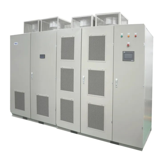
Manufacturer, manufacturing date, etc. 1.5 System Hardware MV510 series drive cabinet outline depends on voltage level, power, model and other related factor. The main structure includes basic control cabinet, power cell cabinet, transformer cabinet, and bypass cabinet. Figure 1-2 shows typical complete assembly of a medium voltage VFD cabinet. -
Page 11: Control Cabinet
MV510 Series High Voltage VFD User Manual Figure 1-2A typical outlines drawing of MV510 series drive 1.5.1 Control Cabinet This cabinet includes main control system, electric control system, user I/O terminals, communication and remote control function. 1.5.2 Power Cell Cabinet Each unit is with a three-phase AC input and a single-phase inverter output. -
Page 12: Bypass Cabinet
MV510 Series High Voltage VFD User Manual standards. 1.5.4 Bypass Cabinet User can choose Bypass Cabinet as required. Bypass function can be implemented in case of VFD failure. The connection of power cables is from Bypass cabinet to Transformer cabinet for input high voltage, and from Bypass cabinet to motor for output voltage. - Page 13 <1000m,Higher altitudes 1000m,For every 100 m derating1% The installation elevation increase Dust Non-conductive, non-corrosive,<6.5mg/dm Protection grade IP30,IP31(customized) Cabinet color RAL7035( customized) ※ Please consult with TECO Co. Ltd. for the information beyond the above table. TECO Electric & Machinery Co., Ltd.
-
Page 14: Chapter Ii Precautions
Chapter II Precautions 2.1 General When MV510 Series VFD is operated or used, safety precautions and relevant operating instructions must be strictly followed. Any incorrect operation may cause personal injuries and equipment damages. In order to prevent any electric shock or burn accident from happening and protect the equipment, be sure to read this manual before using the VFD. -
Page 15: Usage Precautions
MV510 Series High Voltage VFD User Manual (7) Be sure absolutely not to touch the inside of equipment with wet hands. (8) Don’t open cabinet doors and more seriously don’t touch any part inside the equipment within 15 minutes after main power supply is switched off. - Page 16 MV510 Series High Voltage VFD User Manual supply and at last turn off control power supply. (10) During the VFD operation, its user shall supervise the load operation status all the time and timely switch off the VFD if any abnormal status happens.
-
Page 17: Chapter Iii Site Installation Instructions
3.1 Appearance and Weight In this section, we mainly introduce basic appearance of different parts of MV510 Series VFD. We take Model MV510-E60/100-S00 ( automatic bypass ) VFD for example to introduce various parts as follows. See specific outline dimensions of configured VFD in the outside drawing that our company provides to corresponding project. -
Page 18: Transformer Cabinet
MV510 Series High Voltage VFD User Manual Figure 3-2 Outside Drawing of Power Cell 3.1.2 Transformer Cabinet Approximate weight: 3270kg ( including transformer weight ) Figure 3-3 Outside Drawing of Transformer Cabinet 3.1.3 Bypass Cabinet (Optional, Automatic Bypass Cabinet) Approximate weight: 600kg... -
Page 19: Installation Requirements
MV510 Series High Voltage VFD User Manual Figure 3-4 Outside Drawing of Automatic Bypass Cabinet 3.2 Installation Requirements 3.2.1 Installation Environment Accord with the following environment indexes Item Requirement Environment The temperature shall be within the range of 0℃~40℃ temperature... -
Page 20: Storage Environment
MV510 Series High Voltage VFD User Manual In the room where the equipment is installed, the air conditions shall be kept at normal aerial dust standard, especially for iron particles Indoor air quality and organic particles, like organic silicon Corrosion factors Density or quantity Hydrogen sulphide (H... -
Page 21: Vfd Layout
MV510 Series High Voltage VFD User Manual will happen so as to prevent condensation. Store the equipment at a place without dust. Store the equipment at a place without much vibration or shock. Store the equipment at a place without corrosive gases. -
Page 22: Equipment Foundation
MV510 Series High Voltage VFD User Manual Back Front Figure 3-6 Maintenance Space and Ventilation Opening of VFD After the construction is completed, it is requested that the doors, windows and ventilation openings of VFD room shall be completed with installation.VFD room shall have prevention measures against rain, snow,... - Page 23 MV510 Series High Voltage VFD User Manual Vertical tolerance Front and back datum in vertical standard has the tolerance of 1mm for every 1200mm of cabinet depth. Figure 3-8 Vertical Tolerance Drawing Parallel tolerance Datum length in maintenance standard has the tolerance of 1mm for every 1000mm.
-
Page 24: Equipment Grounding
MV510 Series High Voltage VFD User Manual Position for Installing Position for Installing Position for Position for Installing Installing Bypass Cabinet Transformer Cabinet Units Control Cabinet Figure 3-10 General Appearance of VFD Foundation 3.2.5 Equipment Grounding Foundation box iron adopts steel for reliable grounding and see its minimum... -
Page 25: Installation Process
We will handle the situation as soon as possible. 3.3.2 Estimated Weight Because MV510 Series High Voltage VFD changes with the user’s specific application, exact weight of equipment is related to the equipment capacity and chosen optional parts. The equipment’s outline dimension and weight are provided both on its delivery package and in its user drawings. -
Page 26: Cabinet Connection And Fixation
MV510 Series High Voltage VFD User Manual 3.3.4 Cabinet Connection and Fixation After the VFD cabinet is in right place, control cabinet, unit cabinet, transformer cabinet and bypass cabinet shall be connected together, and each cabinet shall be connected to foundation box iron. -
Page 27: Installation Of Power Cells
MV510 Series High Voltage VFD User Manual Table 3-3 Allowable Deviation for Cabinet Body Installation Item Allowable Deviation ( mm ) Perpendicularity ( each meter ) <1.5 Tops of adjacent two <2 cabinets Horizontal deviation Tops of the cabinets in one <5... -
Page 28: High Voltage Insulation Test On Vfd
MV510 Series High Voltage VFD User Manual 3.3.6 High Voltage Insulation Test on VFD After the VFD is in place and before primary cables are connected, high voltage insulation test shall be conducted on the high voltage part of the VFD according to high voltage standard, including bypass cabinet and transformer cabinet. -
Page 29: Electrical Wiring
MV510 Series High Voltage VFD User Manual If the VFD’s rated voltage is 10kV, site test values of the transformer are: Power Frequency Test Item Withstanding Voltage Time ( Effective Value ) High voltage---low voltage AC24kV 1min and ground Low voltage---high voltage... - Page 30 MV510 Series High Voltage VFD User Manual High voltage power supply input VFD input High voltage power supply output (connected to the motor) VFD output Figure 3-12Primary Wiring Terminal Drawing of Bypass Cabinet The cable from Bypass Cabinet to Phase-shifting Transformer: Connect the lower end of QS1 to the primary side terminal of phase-shifting transformer with high voltage flexible cable.
- Page 31 MV510 Series High Voltage VFD User Manual The Cable from Secondary Side Terminal of Phase-shifting Transformer to Power Cell: after VFD cabinet is in place and assembled, just connect two end of the cable with right cable number to secondary side terminal of phase-shifting transformer and input terminal of power cell.
- Page 32 MV510 Series High Voltage VFD User Manual Input of power cell unit Figure 3-155-Level Tandem Connection Diagram The Cable from the Output of Power cell to Bypass Cabinet: After power cells are connected in tandem, connect the output rated voltage of the last level of power cell directly to the lower end of QS2, as shown in Figure 3-12.
- Page 33 MV510 Series High Voltage VFD User Manual Figure 3-16 Diagram of Wiring Terminals inside Transformer Cabinet Wiring terminals of the transformer to bypass cabinet are configured at left side of transformer cabinet, and mainly for the wiring of power supply and status signal of high voltage isolator of bypass cabinet.
-
Page 34: Inspection After Installation
MV510 Series High Voltage VFD User Manual control power supply, the standard wiring terminals are as shown in Figure 3-18: Figure 3-18Diagram of Signal Interfaces between the VFD and Users The secondary wiring terminal diagrams above are wiring diagrams for the VFD of standard configuration ( only for reference ). -
Page 35: Chapter Iv Function Introduction
(5) Communication functions (6) Switch between power frequency grid and the VFD (optional) In order to introduce you more details about our company’s MV510 Series VFD, we explain some of its main functions one by one as follows. 4.2 Control Functions Related to Motor Drive 4.2.1 Control Modes... -
Page 36: Frequency Setting Methods
Whatever the VFD is under which control modes, the operating parameters and fault history of VFD can be displayed and searched on HMI. 4.2.2 Frequency Setting Methods Currently MV510 Series VFD adopts two frequency setting methods: (1) Digital quantity frequency setting. (2) Analog quantity frequency setting. -
Page 37: Torque Boost
MV510 Series High Voltage VFD User Manual If the set frequency value is within the range of resonance frequencies, set frequency will adopt the upper limit value of resonance frequencies, resonance point quantity of mechanical system shall be determined in actual tests by users according to actual load situation. -
Page 38: System Over-Current Limitation
MV510 Series High Voltage VFD User Manual influenced by grid voltage and load changes. 4.2.6 System Over-current Limitation Both load sudden change and short-time over-current during speed rising are unavoidable. As a result, over-current handling principle is to avoid stopping. -
Page 39: Flying Start
MV510 Series High Voltage VFD User Manual and recover to previous working condition in about 200ms. The ability can meet power-losing ride-through and unit cold bypass technology. If the power failure time is relatively long, residue voltage of the motor will quickly decay. In this case, the amplitude of residue voltage can be judged. -
Page 40: Restore Factory Settings
4.3 Input and Output Signal Functions The input and output signals of MV510 Series VFD mainly include digital input, digital output, analog input and analog output. 4.3.1 Digital Input MV510 Series VFD provides 6 basic digital input channels. -
Page 41: Digital Output
Specific requirements shall be put forward in purchase order and technical protocol. 4.3.2 Digital Output MV510 Series VFD provides 6 basic digital output channels, and all the channels are relay junction output. Table 4-2 DO Output Interface Interface Name... -
Page 42: Analog Input
In addition to monitor voltage and current, it also provides 2 external analog input channels, which can be 4~20mA current signal or 0~10V voltage signal. The definition of analog input of MV510 Series VFD is provided in Table 4-3. Table 4-3 Analog Input Interface... -
Page 43: Supervision And Display Functions
4.4 Supervision and Display Functions MV510 Series High Voltage VFD has a set of human-machine interface that is very concise and easy to operate, and applies the touch screen produced by Beijing Kunluntongtai Company. It provides many choices to users and has both monitoring... -
Page 44: Switch Between Power Grid And Vfd (Optional)
MV510 Series High Voltage VFD User Manual 4.6 Switch between Power Grid and VFD (Optional) In order to avoid interrupting the production, MV510 Series High Voltage VFD is configured with bypassing MV510.If the VFD needs to be repaired or maintained, or bears any fault, the motor can be switched to line to operate so that the system can keep working. -
Page 45: Chapter V Operating Principles
MV510 Series VFD is “High-High” type of high voltage VFD that applies new type high voltage and high power electrical and electronic VFDs. Through... -
Page 46: Main Circuit
MV510 Series High Voltage VFD User Manual 5.2 Main Circuit MV510 Series VFD is composed of multiple power cells in cascade, and high voltage output is achieved by superposing the outputs of multiple low voltage power cells. Figure 5-1 is typical circuit topological graph of 6kV series high voltage VFD. -
Page 47: Phase-Shifting Transformer
Figure 5-2. Input voltage of MV510 Series High Voltage VFD is similar to sine wave and causes little harmonic pollution to power grid. Its total harmonic distortion is lower than 4%. -
Page 48: Power Cells
MV510 Series High Voltage VFD User Manual Figure 5-2 Actually Measured Line Voltage Waveform at Input Side 5.2.2 Power Cells See the structure diagram of power cells in Figure 5-3. The structure of each power cell is same and interchangeable. Each power cell contains input fuse, rectifier bridge, filter capacitor and IGBT VFD bridge. - Page 49 MV510 Series High Voltage VFD User Manual Figure 5-3 Power Cell Structure Diagram Each power cell receives the modulation information sent by master controller through optical communication to generate the voltage and frequency that the motor requires, and each power cell’s status information (including normal working condition and fault information) is also sent to master control system through optical fiber.
- Page 50 MV510 Series High Voltage VFD User Manual Figure 5-4 Actually Measured Output Waveform of Power Cell Each cell outputs 3 different voltages that are +U, O and –U. For each phase, 5 power cells are superposed in cascade togenerate multilevel phase voltage waveforms, with 11 electrical levels that are O, ±U, ±2U, ±3U, ±4U and...
- Page 51 MV510 Series High Voltage VFD User Manual Figure 5-5 Actually Measured Line Voltage Waveform at Output Side Compared with other competitors’ products, the power cells configured with MV510 Series have the following advantages: (1) Real-time sampling of temperature Owing to the heat sink of power cell with NTC resistor, pulses are generated through PWM comparison circuit, then decoded by FPGA and uploaded to DSP.
- Page 52 MV510 Series High Voltage VFD User Manual which is different from the case that other manufacturers just apply the comparator of hardware configuration as fault protection inside power cell. Our design provides very high guarantee on the improvement of software performance.
-
Page 53: Control System
5.3 Control System Control system includes master control system and electrical control system. Structure schematic diagram of control system in MV510 Series VFD is as shown in Figure 5-6. TECO Electric & Machinery Co., Ltd. -
Page 54: Master Control System
Such optical fiber is the only connection between power cells and master control system so main circuit of MV510 Series High Voltage VFD is electrically separated from control system totally. -
Page 55: Electrical Control System
MV510 Series High Voltage VFD User Manual 5.3.2 Electrical Control System Electrical control system includes power supply part, logic control system (including PLC and electrical control components) and HMI (human-machine interface). PLC adopts S7-1200/AP-200 with high reliability to conduct the control on input and output signals of the VFD. -
Page 56: Chapter Vi Site Commissioning Instructions
MV510 Series High Voltage VFD User Manual Chapter VI Site Commissioning Instructions 6.1 Range This chapter specifies the VFD’s site commissioning instructions, including the VFD’s test items, site test requirements and steps. Users can take it as reference to formulate site commissioning schemes, and our company’s service personnel can... -
Page 57: Commissioning Instructions
MV510 Series High Voltage VFD User Manual accordance with specified content and steps. No-load Test with Motor: After cascade test of power cells of the VFD is passed, connect the motor without load, and conduct a test in accordance with specified content and steps. -
Page 58: Simulation Test
MV510 Series High Voltage VFD User Manual and reliable according to design documents. Check if wiring connection is correct, unloosening, and reliable inside control cabinet according to design documents. Check various grounding wires are correct and reliable in accordance with... - Page 59 MV510 Series High Voltage VFD User Manual (1) Process of Simulation Test Check and confirmation→ Turn on control power of AC380V→ Conduct Simulation Test→ Turn off control power of AC380V. (2)Items of Simulation Test Check if the following various main actuators work well.
-
Page 60: Individual Test
MV510 Series High Voltage VFD User Manual 6.3.4 Individual Test Safety Precautions: 1. Conduct individual test of power cell of the VFD only after simulation test is qualified. 2. After the VFD’s primary power is turned on, it’s prohibited to operate isolating switch. -
Page 61: Cascade Test Of Power Cells
MV510 Series High Voltage VFD User Manual all the abnormal voltage PWM waveforms. If output waveforms of all the power cells are normal, read the effective values of output voltage on each power cells by using an oscilloscope, and record them. -
Page 62: Load Test With Motor
MV510 Series High Voltage VFD User Manual voltage waveform of the VFD at 10Hz, 20Hz, 30Hz, 40Hz and 50Hz by using an oscilloscope and high voltage probe, and record the results. The oscilloscope shall display effective voltage values. During the VFD’s operation, measure and record the temperature at air intake of power cell cabinet. - Page 63 MV510 Series High Voltage VFD User Manual primary power switch.→ Wait power cells to run out of power→ Correct the motor wiring→ Check and confirm→ Turn on the VFD’s primary power switch.→ After the motor’s rotating direction is correct, increase the frequency.→...
-
Page 64: Load Test With Motor
MV510 Series High Voltage VFD User Manual current values. When the motor is running under the minimum allowed rotating speed, request the user to arrange staff to pay attention on the motor’s temperature rise all the time. Measure the motor’s axle temperature. - Page 65 MV510 Series High Voltage VFD User Manual VFD operates→ Check voltage and current waveforms→ Stop→ Turn off the VFD’s primary power switch→ Turn off control power of AC380V. (2) Test Items of Load Test with Motor Choose local control mode for the VFD operation. With an oscilloscope and current probe, observe and record: The current waveforms at the VFD’s output side and the transformer’s input side at 10Hz, 20Hz,...
-
Page 66: Run Test With Load Connected
MV510 Series High Voltage VFD User Manual 6.3.8 Run Test with Load Connected Safety Precautions: 1. Conduct Run Test with load connected on the VFD only after its load test with motor is qualified. 2. After the VFD’s primary power is connected, it’s prohibited to close isolating switch. -
Page 67: Chapter Vii Troubleshooting And System Maintenance
Chapter VII Troubleshooting and System Maintenance 7.1 Fault Classification MV510 Series VFD has complete fault monitoring and protection functions, and its faults can be classified into major faults and minor faults ( alarms ). When faults happen, the VFD firstly conducts corresponding reactions in accordance with fault types. - Page 68 MV510 Series High Voltage VFD User Manual (4) The motor freely stops (5) Display happening time and description of major fault on touch screen Common system faults, reasons and corresponding measures are respectively introduced as follows. When operators find any system fault, they shall arrange to eliminate the fault as soon as possible to guarantee the system works well and timely notify our company.
- Page 69 MV510 Series High Voltage VFD User Manual normal. Check ambient temperature of VFD room is up to standard, and input current is normal. Causes: Find out the causes according to fault description on HMI. “ Bus under voltage” means cell bus voltage is below the protection value.
- Page 70 MV510 Series High Voltage VFD User Manual is normal. Check whether interface hardware is damaged. Cause: Frequency value set by DCS is HMI displays “ Analog signal not detected by the VFD. Analog signal loss loss”, and the VFD is still Remedies: running.
- Page 71 MV510 Series High Voltage VFD User Manual Check operating condition of motor, or any sudden change of load. Cause: Output blocked after 3s time delay when output current is 1.5 times higher than the rated current of motor. Remedies: Check whether the “over HMI displays “Output...
- Page 72 MV510 Series High Voltage VFD User Manual output of the VFD. protection when the current of motor is 1.1 times higher than its rated level. Remedies: Check whether the “over temperature threshold” and “over temperature time constant” parameters are correct.
- Page 73 MV510 Series High Voltage VFD User Manual rated voltage. Remedies: Refer to “input over voltage”. Causes: Find out the causes according to fault description on HMI. “ Bus over voltage” means cell bus voltage exceeds the protection value. “ VFD fault” means IGBT failure.
- Page 74 MV510 Series High Voltage VFD User Manual Cause: Abnormal loss of high voltage is detected by the VFD. Remedies: Find out the reasons of high voltage loss. HMI displays “ High Check whether the High voltage loss voltage loss during...
-
Page 75: System Maintenance
MV510 Series High Voltage VFD User Manual under overload state for a long time. 7.2 System Maintenance The influence of service environment factors like temperature, humidity, pH value, dust and vibration of service environment as well as many other reasons like aging and wear of inside parts of the VFD will cause potential fault risks to the VFD. -
Page 76: Maintenance Instructions
MV510 Series High Voltage VFD User Manual (9) Pay attention to handle the VFD’s power cells with care when transporting them. (10) Power cells must be stored on racks in ware house. In special circumstance, they can be put on ground for a short time but the ground must be dry and flat. - Page 77 MV510 Series High Voltage VFD User Manual (6) After the VFD passes acceptance check through 72 hours of pilot run, various connection nuts for the VFD’s inside cables shall be tightened again. (7) Various connection nuts for the VFD’s inside cables shall be tightened again within half year.
- Page 78 MV510 Series High Voltage VFD User Manual (7) The temperature at air outlet of power cell cabinet in the VFD can’t be over 50℃. (8) Check the operation of cooling fan of VFD system. Once finding the fan of the VFD or input transformer stops running, please notify professional staff to repair it.
- Page 79 MV510 Series High Voltage VFD User Manual Check if there is any abnormal audio noise or vibration, loosen Cooling bolt and color change caused by over temperature Check if the clearances at air intake and outlet of heat sink are system blocked or attached with foreign matter.
- Page 80 MV510 Series High Voltage VFD User Manual Enable sync. synchronous Esti. Estimated T.C. Time Constant Field Programmable Gate FPGA temp. temperature Array Uninterruptible Power FREQ Frequency Supply Human Machine Interface Undervoltage High Voltage Variable Frequency Drive Jump Frequency A1, A2,.. B1, B2,.. C1,C2,..
- Page 81 Corpright@2016 Taian Technology (Wuxi) Co., Ltd. No part of this specification may be reproduced in any form or means, without the prior written consent of Taian.
Need help?
Do you have a question about the MV510 Series and is the answer not in the manual?
Questions and answers