Table of Contents
Advertisement
Quick Links
Advertisement
Table of Contents

Related Manuals for Nibe ERS 20-250


Summary of Contents for Nibe ERS 20-250
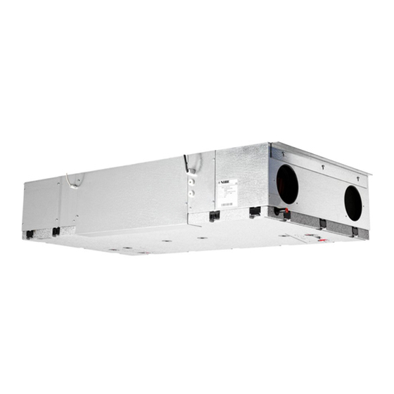
- Page 1 IHB EN 2001-1 INSTALLER MANUAL 531798 Ventilation heat exchanger NIBE ERS 20-250...
-
Page 3: Table Of Contents
Ventilation flow Adjusting ventilation Dimension and ventilation connections Preheating outdoor air 5 Electrical connection Connecting to main product Outside air sensor 6 Commissioning and adjusting Preparations Filling Start-up and inspection 7 Program settings Start guide NIBE ERS 20-250 Table of Contents... -
Page 4: Important Information
Improper disposal of the product by the user results in This symbol indicates tips on how to facilitate administrative penalties in accordance with current le- using the product. gislation. Chapter 1 | Important information NIBE ERS 20-250... -
Page 5: Inspection Of The Installation
In addition, fill in the page for the installation data in the User Manual. Description Notes Signa- Date ✔ ture Electricity (page 13) Connections Main voltage Fuses property Earth circuit-breaker NIBE ERS 20-250 Chapter 1 | Important information... -
Page 6: Delivery And Handling
• The ventilation heat exchanger’s installation area should always have a temperature of at least 10 °C and max. 35 °C. Supplied components 2 x roof brackets Chapter 2 | Delivery and handling NIBE ERS 20-250... -
Page 7: Removing The Covers
Slacken off the four screws holding the side panel. Move the panel out and downwards. L E K Unscrew all the screws holding the bottom panel. L E K Lift the bottom panel down. L E K NIBE ERS 20-250 Chapter 2 | Delivery and handling... -
Page 8: The Ventilation Heat Exchanger Design
3 The ventilation heat exchanger design XL33 XL31 XL32 XL34 HQ11 QN37 EP26 HQ10 XL40 BT21 BT23 BT20 BT22 Chapter 3 | The ventilation heat exchanger design NIBE ERS 20-250... -
Page 9: Pipe Connections
Exhaust air fan Supply air fan HQ10 Exhaust air filter HQ11 Supply air filter QN37 Bypass damper Miscellaneous Type plate Condensation water trough Designations according to standard EN 81346-2. NIBE ERS 20-250 Chapter 3 | The ventilation heat exchanger design... -
Page 10: Pipe And Ventilation Connections Mounting
During operation, negative pressure arises in the ventilation heat exchanger, which means Secure ERS 20 with screws. that a water column of at least 100 mm must be guaranteed in the water seal. Chapter 4 | Pipe and ventilation connections NIBE ERS 20-250... -
Page 11: General Ventilation Connections
The distance should not be less than 1.5 m, but this can vary between different in- stallations. Always use a kitchen fan when cooking. NIBE ERS 20-250 Chapter 4 | Pipe and ventilation connections... -
Page 12: Ventilation Flow
Dimension and ventilation connections Exhaust air Supply air Ø125 Ø125 Outdoor air Extract air Chapter 4 | Pipe and ventilation connections NIBE ERS 20-250... -
Page 13: Electrical Connection
ERS 20 must not be powered during installa- Use cable type LiYY, EKKX or similar. tion. AA5-S2 NOTE If the supply cable is damaged, only NIBE, its service representative or similar authorised person may replace -X10 it to prevent any danger and damage. NOTE AA5-X4... - Page 14 GND (green) GND (grön) AA5-X4 ERS 20 AA5-X4 A (white) A (vit) B (brown) B (brun) GND (green) GND (grön) See the main product’s Installer Manual for the placing of the input board. Chapter 5 | Electrical connection NIBE ERS 20-250...
-
Page 15: Outside Air Sensor
(BT23) in ERS 20. The enclosed outdoor air sensor EAH is placed in the outdoor air duct and connected to the accessory board (AA5) according to the Installer Manual for EAH. NIBE ERS 20-250 Chapter 5 | Electrical connection... -
Page 16: Commissioning And Adjusting
An incorrectly set ventilation flow can damage Temperatur Temperature efficiency the house and may also increase energy con- (°C) sumption. NOTE Order a ventilation adjustment to complete the setting. (l/s) 100 150 350 400 Airflow Luftflöde (m³/h) Chapter 6 | Commissioning and adjusting NIBE ERS 20-250... -
Page 17: Program Settings
If you do not make all settings via the start guide or need to change any of the settings, this can be done in the menu system. Menu 5.2.4 -system settings Activating/deactivating of accessories. Activate: "exhaust/supply air module". NIBE ERS 20-250 Chapter 7 | Program settings... -
Page 18: Disturbances In Comfort
1.2 for the F-Series and select "normal". • External switch for changing the fan speed activated. – Check any external switches. • Fan running slow because of low incoming outdoor air temperature. Chapter 8 | Disturbances in comfort NIBE ERS 20-250... -
Page 19: Accessories
ELECTRICAL AIR HEATER EAH 20 In cold weather, EAH 20-900 heats the incoming outdoor air slightly to prevent the condensation in ERS 20 from freezing. Used mainly in colder climates. Part no. 067 604 NIBE ERS 20-250 Chapter 9 | Accessories... -
Page 20: Technical Data Dimensions Ers
10 Technical data Dimensions ERS 20 1271 (1367 incl. roof mounting) 1271 (1367 inkl takfäste) 1202 Ø15 Ø125 Ø125 Chapter 10 | Technical data NIBE ERS 20-250... -
Page 21: Technical Specifications
Length, supply cable Length, control cable Width 1,202 Height Depth Weight Part no. 066 167 105 m /h at 50 Pa 250 m /h at 140 Pa Scale for efficiency class: A+ to G. NIBE ERS 20-250 Chapter 10 | Technical data... -
Page 22: Energy Labelling
General ventilation connections on page 11. Information about pre-/disassembly See section Recovery on page 4. This installer manual can also be accessed at nibe.eu. The annual electricity consumption kWh/year Annual heating saved, kWh primary energy per year Average: 4,356 prim/year... -
Page 23: Electrical Circuit Diagram
ELECTRICAL CIRCUIT DIAGRAM NIBE ERS 20-250 Chapter 10 | Technical data... -
Page 27: Contact Information
Tel: +46 (0)433-27 3000 kuzmin@evan.ru info@nibe.se nibe-evan.ru nibe.se SWITZERLAND NIBE Wärmetechnik c/o ait Schweiz Industriepark, CH-6246 Altishofen Tel. +41 (0)58 252 21 00 info@nibe.ch nibe.ch For countries not mentioned in this list, contact NIBE Sweden or check nibe.eu for more information. - Page 28 WS version: a1 (working edition) Publish date: 2020-02-13 15:54 This manual is a publication from NIBE Energy Systems. All product illustrations, facts and data are based on the available information at the time of the publication’s approval. NIBE Energy Systems makes reservations for any factual or printing errors in this manual.
Need help?
Do you have a question about the ERS 20-250 and is the answer not in the manual?
Questions and answers