Table of Contents
Advertisement
Quick Links
Energy Efficient
•
Easy to Install
•
Extended Service Life
•
- Energy efficient compact blower coils
- Ideal for educational, hospitality, multi-family, or other commercial environments
- Designed for ducted applications
- Nominal CFM range of 600 to 3,000 CFM
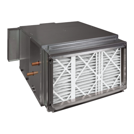
Direct Drive Blower Coils
INSTALLATION, OPERATION, & MAINTENANCE MANUAL
HDY
Horizontal and Vertical
VDY
Advertisement
Table of Contents

Subscribe to Our Youtube Channel
Related Manuals for Nibe IEC VDY


Summary of Contents for Nibe IEC VDY
- Page 1 Horizontal and Vertical Direct Drive Blower Coils INSTALLATION, OPERATION, & MAINTENANCE MANUAL Energy Efficient • Easy to Install • Extended Service Life • - Energy efficient compact blower coils - Ideal for educational, hospitality, multi-family, or other commercial environments - Designed for ducted applications - Nominal CFM range of 600 to 3,000 CFM...
- Page 2 Horizontal and Vertical Direct Drive Blower Coils INSTALLATION, OPERATION, & MAINTENANCE MANUAL It is the responsibility of the end user to properly characterize and dispose of all waste materials according to applicable regulatory and legal entities. Where reasonable, safe, and compliant with local regulatory and legal requirements, IEC encourages recycling materials when disposing of its products. International Environmental Corporation (IEC) works continually to improve its products. As a result, the design and specifications of each product may be changed without notice and may not be as described herein. Please contact IEC for information regarding current design and product specifications. Statements and other information contained herein are not express warranties and do not form the basis of any bargain between the parties but are merely IEC’s opinion or commendation of its products. Manufacturer’s standard limited warranty applies.
-
Page 3: Table Of Contents
Horizontal and Vertical Direct Drive Blower Coils INSTALLATION, OPERATION, & MAINTENANCE MANUAL Table of Contents SECTION ONE — Preface Control Board Adjustment Water Balancing System Introduction Water Treatment Safety Electronically Commutated SECTION TWO — Pre-Installation Motor (ECM) Unpacking and Inspection SECTION FIVE — Service/Maintenance Prepare Job Site for Unit Installation General Identify and Prepare Units... -
Page 4: Section One - Preface
Horizontal and Vertical Direct Drive Blower Coils INSTALLATION, OPERATION, & MAINTENANCE MANUAL SECTION ONE — Preface Introduction CAUTION: Electric shock can cause death. International Environmental Corporation (IEC) fan coil units represent a prudent investment offering trouble- CAUTION: Observe all warnings and precautions free operation and long service with proper installation, marked on the equipment. operation, and regular maintenance. The equipment covered by this manual is available with a variety of Install approved Lock-Out/Tag-Out protection devices on options and accessories. Always consult the approved unit ALL incoming power sources to equipment being installed or serviced prior to beginning any work. Always verify submittals, order acknowledgement, and other manuals all incoming power sources are de-energized using an for specific details on unit options and accessories. Always electrical multi-meter. follow proper procedures related to safety, handling, installation, operation, and servicing of mechanical CAUTION: Never wear bulky or loose fitting equipment as the manufacturer assumes no responsibility clothing when working on any mechanical for personal injury or property damage resulting from equipment. -
Page 5: Section Two - Pre-Installation
Horizontal and Vertical Direct Drive Blower Coils INSTALLATION, OPERATION, & MAINTENANCE MANUAL SECTION TWO — Pre-Installation Improper installation, adjustment, service, maintenance, At time of receipt, equipment type and arrangement or use can cause explosion, fire, electrical shock, or other must be verified by review of order documents. Should conditions, which may result in personal injury or property any discrepancy be found, the local Sales Representative damage. This product must be installed only by personnel must be notified immediately so that proper action may with the training, experience, skills, and applicable be taken. licensing that makes him/her “a qualified professional Should any questions arise concerning field warranty HVACR installer”. repairs, factory must be notified BEFORE any corrective action is taken. SECTION 2 – Pre-Installation When repairs or alterations can be accomplished locally, the factory must be fully informed of the extent and Unpacking and Inspection expected cost of repairs before work begins. When All units are carefully inspected at the factory throughout factory operations are required, the factory must be the manufacturing process under a strict detailed quality contacted for authorization to return equipment and a assurance program. All major components and sub- Return Authorization Number will be issued. -
Page 6: Protect Units From Damage
Horizontal and Vertical Direct Drive Blower Coils INSTALLATION, OPERATION, & MAINTENANCE MANUAL SECTION THREE — Installation 2. Rotate fan wheel by hand to ensure that fan is for 1/2" (12.70 mm) all thread (not supplied with unit) to unrestricted and can rotate freely. Inspect for pass through (see Figure 3). Always support the unit at shipping damage and fan obstructions. Adjust the base until mounting is complete. blower wheel as required. Sufficient clearance must be kept for service and maintenance. Minimum recommended clearance for Protect Units from Damage maintenance of the motor and blower wheel is 29" Care must be taken to assure that no force or pressure (736.60 mm) on each side. Filters can be removed from is applied to the coil, piping or drain stub-outs during both sides and the bottom (HDY) or top (VDY) of the handling. The equipment covered in this manual IS filter frame. If side access to the filter is desired, the NOT suitable for outdoor installations. The equipment minimum clearance required is the width of the filter rack is never to be stored or installed where it may be plus 6" (154.40 mm). subjected to a hostile environment such as rain, snow, or extreme temperatures. A minimum of 48" (121.92 cm) clearance is required between factory supplied electric heater and any Before, during, and after installation, take specific caution combustible materials. (See Figures 1 and 2 for to prevent foreign material such as paint, plaster, and additional clearances information). drywall dust from being deposited in the drain pan, on the motor or blower wheels and cooling/heating coils. For drain pan removal, the recommended clearance Failure to do so may have serious adverse effects on unit should be no less than the width of the unit. - Page 7 Horizontal and Vertical Direct Drive Blower Coils INSTALLATION, OPERATION, & MAINTENANCE MANUAL SECTION THREE — Installation, Cont’d. Figure 2. VDY Unit installation – Figure 4. HDY Mounting details - threaded rod suspension recommended clearances (top view) AIRFLOW FILTER Washer IOM-092 corrections 8.2.2023 Double Nuts Trapeze PIPING PACKAGE Bolt...
-
Page 8: Total Weight Unit Correction
Horizontal and Vertical Direct Drive Blower Coils INSTALLATION, OPERATION, & MAINTENANCE MANUAL SECTION THREE — Installation, Cont’d. Figure 6. VDY Distributed Weight Calculations LH COIL RH COIL NOTE: Some unit components are removed for clarity. Table 2. VDY Operating weight/Distributed weight values No Electric Heat (lb.) With Electric Heat (lb.) VDY Unit Total Total NOTE: 1. Unit weights (shown in pounds), +/- 10 percent, are based on the largest water-filled coil. 2. The operating weight information is based on 8-row water filled coils and double wall cabinet construction. For different coil and cabinet options, use the weight adjustment table (Table 2). Total Weight Unit Correction Factor (lb.) Table 3. -
Page 9: Mixing Box Installation
Horizontal and Vertical Direct Drive Blower Coils INSTALLATION, OPERATION, & MAINTENANCE MANUAL SECTION THREE — Installation, Cont’d. Mixing Box Installation Figure 9. Horizontal units with mixing box option 1. Mixing boxes are pre-assembled from the factory for ease of installation. A linkage kit consisting of two crank arms, 2 swivels, and either a 25" (635.00 mm) (sizes 06-16) or a 34" (863.60 mm) (sizes 20-30) length of 5/16" (7.94 mm) rod is provided for field installation of an actuator. Figure 7. Base rails MOUNTING MOUNTING LOCATION LOCATION DETAIL A DETAIL B Figure 10. VDY mixing box installation 2. Assemble the base rails (provided with mixing box). All hardware required for assembly is included and the base rails are letter coded for ease of assembly (as shown in Figure 8). Figure 8. -
Page 10: Inlet And Outlet Dampers Installation
Horizontal and Vertical Direct Drive Blower Coils INSTALLATION, OPERATION, & MAINTENANCE MANUAL SECTION THREE — Installation, Cont’d. Inlet and Outlet Dampers Installation 5. Install Swivels to Crank Arms, hand tighten. 1. Install actuator per manufacter’s instructions. Figure 12. Install swivels 2. Adjust damper shafts outward to extend past any obstacles that might cause interference. Do not adjust inward end of shaft within a distance of 2 inch of bronze bushing. 3. Position inlet damper and outlet damper to SEE DETAIL A coincide with current or intented position of actuator arm, depending on actuator’s position (opened/closed). Note rotation direction of each DETAIL A damper. 4. Install crank arms to each damper shaft approximately parallel to each other while maintaining state/position of dampers, as show in Figure 11. Check for range of motion clearances before tightening. 6. Insert 5/16” (7.94 mm) damper rod through Figure 11. -
Page 11: Cooling/Heating Pipe Connections
Horizontal and Vertical Direct Drive Blower Coils INSTALLATION, OPERATION, & MAINTENANCE MANUAL SECTION THREE — Installation, Cont’d. Cooling/Heating Pipe Connections Piping Insulation CAUTION: Residue and loose particles resulting After system integrity has been established, insulate the from manufacturing and field piping techniques piping in accordance with the project specifications. This is such as joint compounds, soldering flux, and metal the responsibility of the installing or insulation contractor. shavings may be present in the unit and the piping Condensate Drain system. -
Page 12: Maximum External Static Pressures
Horizontal and Vertical Direct Drive Blower Coils INSTALLATION, OPERATION, & MAINTENANCE MANUAL SECTION THREE — Installation, Cont’d. Maximum External Static Pressures Connecting Ductwork All ductwork shall be installed in accordance with the HDY/VDY HDY/VDY Model Minimum Minimum project plans and specifications. See Figures 23-26 for Max ESP Max ESP supply and return duct flanges location and dimensions H**/V**06 0.17 0.04 NOTE: When installing units that attach to branch duct H**/V**08 1.35 0.36 piping, use industry approved duct standards H**/V**10 1.75 0.52 and configuration such as those published by ... -
Page 13: Section Four - Start-Up
Horizontal and Vertical Direct Drive Blower Coils INSTALLATION, OPERATION, & MAINTENANCE MANUAL SECTION FOUR — Start-Up 7. Ensure all panels and filters are installed before on the coil (Figure 15). Manual air vents are basic schrader checking fan operation. Turn on power to the unit. valves that could be accessed from the coil side of the unit 8. Inspect the fan and motor operation. and are located between the coil header and end sheet. To vent the air from the coil, depress the valve until the air has vented the coil. When water begins to escape through SECTION 4 – Start-Up the valve, release the valve. Automatic air vents may be unscrewed one turn Before beginning any startup operation, the startup counterclockwise to speed initial venting, but should be personnel shall familiarize themselves with the unit, screwed in for automatic venting after startup operations. options and accessories, and control sequence to understand the proper system operation. All personnel Figure 15. Air vents shall have a good working knowledge of general startup procedures and have the appropriate startup and balancing guides available for consultation. Manual Air Vent The building must be completely finished including doors, windows, and insulation. All internal walls and doors should be installed. In some cases, the interior decorations... -
Page 14: Air Balance System
Horizontal and Vertical Direct Drive Blower Coils INSTALLATION, OPERATION, & MAINTENANCE MANUAL SECTION FOUR — Start-Up, Cont’d. Air Balance System CAUTION: Only trained and qualified individuals should attempt to adjust or service components All ductwork must be complete and connected. All filters on any energized electrical equipment. Failure to follow and access doors and panels must be properly installed established safety rules and guidelines could result in to establish actual system operating conditions BEFORE serious injury or death. beginning air balancing operations. Each individual unit and the attached ductwork is a Figure 16. Motor Control Board unique system with its own operating characteristics. For this reason, air balancing is normally done by balance specialists who are familiar with all procedures required... -
Page 15: Water Balancing System
Horizontal and Vertical Direct Drive Blower Coils INSTALLATION, OPERATION, & MAINTENANCE MANUAL SECTION FOUR — Start-Up, Cont’d. at the time of order, while Medium and Low Speeds are Water Balancing System set to defaults based on High speed. Should airflow A complete knowledge of the hydronic system, along with require adjustment after installation, the control board its components and controls, is essential to proper water settings for Low, Medium and High could be adjusted by system balancing. This procedure shall not be attempted turning screws (as shown in the picture) using a small by unqualified personnel. The system must be complete, Phillips Screwdriver. It will adjust the control voltage to the and all components must be in operating condition motor. A clockwise rotation increases the voltage to the BEFORE beginning water system balancing operations. motor, while counter clockwise rotation reduces it. Each hydronic system has different operating characteristics CAUTION: On units with Electric Heat – the depending on the devices and controls used in the system. factory default setting for Low airflow prevents ... -
Page 16: Electronically Commutated
Horizontal and Vertical Direct Drive Blower Coils INSTALLATION, OPERATION, & MAINTENANCE MANUAL SECTION FIVE — Service/Maintenance Motor/Blower Assembly Table 4. Water quality parameters Fan operation type is determined by the control Water Containing Required Concentration components and their method of wiring. This may vary Sulphate Less than 200 ppm from unit to unit. Refer to the wiring diagram attached to 7.0 – 8.5 each unit for individual operating characteristics. Chlorides Less than 200 ppm Nitrate Less than 100 ppm All motors have permanently lubricated ball bearings. No Iron Less than 4.5 mg/l field lubrication is required. Ammonia Less than 2.0 mg/l Manganese Less than 0.1 mg/l Should the motor/blower assembly require service, it may Dissolved Solids Less than 1000 mg/l be removed from unit to facilitate operations such as CaCO3 Hardness 300 - 500 ppm motor or blower wheel/housing replacement, etc. CaCO3 Alkalinity 300 - 500 ppm Particulate Quantity... -
Page 17: Coils
Horizontal and Vertical Direct Drive Blower Coils INSTALLATION, OPERATION, & MAINTENANCE MANUAL SECTION FIVE — Service/Maintenance, Cont’d. Figure 18. operation. This device only operates when a problem exists, ANY condition that causes high-limit cutout MUST IONIZATION be corrected immediately. High supply voltage also causes INDICATOR BRUSH LIGHT excessive amperage draw, and may trip the circuit breaker or blow the fuse(s) on incoming power supply. After proper airflow and supply power are assured, regular filter maintenance is important to provide clean air over the heater. Dirt allowed to deposit on the heating element will cause hot spots and eventual element burn through. These hot spots will normally not be enough to trip the high-limit thermal cut-out device, and may not be FRONT VIEW evident until actual heater element failure. Coils Cabinet/Control Box Maintenance Light – HDY Coils should be cleaned by removing the motor/blower Optional LED Service Light provides a source of assemblies and brushing the entering air face between illumination in the main unit cabinet and the control box fins with a stiff brush. Brushing should be followed during routine maintenance and troubleshooting in the by cleaning with a vacuum cleaner. If a compressed dark ceiling spaces. -
Page 18: Drain
Horizontal and Vertical Direct Drive Blower Coils INSTALLATION, OPERATION, & MAINTENANCE MANUAL SECTION FIVE — Service/Maintenance, Cont’d. the equipment in compliance with governing codes, Filters, Replacement, Installation ordinances and testing agency listings. Each unit is equipped with return air filters. Filters must be periodically replaced. Drain Units’ filters are 1” (25.40 mm), 2” (50.80 mm) or 4” Inspect drain before initial startup, and prior to each (101.60 mm) thick. Filters can be easily accessed from the cooling season to assure that drain trap and line are clear. side or bottom of the filter rack (See Figures 19 and 20). When clogged, clear the debris so condensate easily flows. To remove filters from the side of the filter rack: Periodically inspect drain during cooling season to 1. Remove the side access panel (A) of the filter rack maintain a free-flowing condensate. Units are provided by pulling tab at the bottom (HDY or top (VDY) of with a secondary or “tell-tale” drain connection that will the panel to free from magnets, and lower it out of indicate a clogged main-drain line by flow from “tell-tale” the slot (B) in the top of the filter frame connection. 2. Pull out dirty filters. 3. Replace with new appropriate size filters. Should algae and/or bacteria growth become a concern, 4. To re-install side access panel into filter rack : consult an air conditioning and refrigeration supply a) Insert the tab of panel into the slot in filter organization familiar with local conditions for chemicals, or frame’s top (B). - Page 19 Horizontal and Vertical Direct Drive Blower Coils INSTALLATION, OPERATION, & MAINTENANCE MANUAL SECTION FIVE — Service/Maintenance, Cont’d. Figure 19. HDY Filter rack 4” Filter Filter Support Angle Bracket See Detail X 1” Filter Slot See Detail Y 2” Filter Slot Filter Support Angle Bracket 1”...
- Page 20 Horizontal and Vertical Direct Drive Blower Coils INSTALLATION, OPERATION, & MAINTENANCE MANUAL SECTION FIVE — Service/Maintenance, Cont’d. Figure 20. VDY Filter rack 2" FILTER MAGNETS 1" FILTER SEE DETAIL X SEE DETAIL Y DETAIL X FILTER SUPPORT ANGLE BRACKET 4" FILTER FILTER SUPPORT ANGLE BRACKET 2" FILTER BRACKET MOUNTING HOLES 1" FILTER BRACKET MOUNTING HOLES DETAIL Y...
-
Page 21: Piping Connection Location
Horizontal and Vertical Direct Drive Blower Coils INSTALLATION, OPERATION, & MAINTENANCE MANUAL SECTION FIVE — Service/Maintenance, Cont’d. Piping Connection Location (Centerline to Centerline): Hydronic Cooling and Heating Coils Figure 11. Hydronic coil piping connection diagram CR - Cold Water Return HR - Hot Water Return CS - Cold Water Supply HS - Hot Water Supply RH - Right Hand LH - Left Hand 2(51) 1-5/8(41) Horizontal, left hand unit with re-heat coil shown. Coil Header Connection Size DIMENSIONS - INCHES (MILLIMETERS) Unit 8 Row... - Page 22 Horizontal and Vertical Direct Drive Blower Coils INSTALLATION, OPERATION, & MAINTENANCE MANUAL SECTION FIVE — Service/Maintenance, Cont’d. Piping Connection Location (Centerline to Centerline): Hydronic Cooling and Heating Coils, Cont’d. Table 3. Hydronic coil piping connections Coil Rows DIMENSIONS - INCHES (MILLIMETERS) Unit Size Cool Heat – – – – – 3-1/2 (88.900) 15-1/2 (393.700) 7 (177.800) 7 (177.800) 5-15/16 (150.813) 3-13/16 (96.838) 15-13/16 (401.638) 7-9/16 (192.088) 7-9/16 (192.088) 06/08 – – 6-1/8 (155.575) 12-3/4 (323.850) –...
- Page 23 Horizontal and Vertical Direct Drive Blower Coils INSTALLATION, OPERATION, & MAINTENANCE MANUAL SECTION FIVE — Service/Maintenance, Cont’d. Table 7. Electric heater data Table 8. Electric heater data availability FULL LOAD AMPS UNIT SIZE Single-Phase Three-Phase 20/22 120 V 208 V 240 V 277 V 208 V 240 V 480 V...
- Page 24 Horizontal and Vertical Direct Drive Blower Coils INSTALLATION, OPERATION, & MAINTENANCE MANUAL SECTION FIVE — Service/Maintenance, Cont’d. Table 9. Motor Performance Data (Full Load AMPS) UNIT SIZE 06, 10 08, 12, 16, 20 MOTOR TYPE VOLTAGE MOTOR HORSEPOWER AND FLA 1/2 HP 1 HP 1-1/2 HP 3 HP 115V/1 PHASE/50-60 HZ 10.7 208V/1 PHASE/50-60 HZ 1-PHASE SINGLE SPEED STANDARD EFFICIENCY 230V/1 PHASE/50-60 HZ 277V/1 PHASE/50-60 HZ 208V/3 PHASE/50-60 HZ...
-
Page 25: Appendix I - Typical Wiring Diagram Examples
Horizontal and Vertical Direct Drive Blower Coils INSTALLATION, OPERATION, & MAINTENANCE MANUAL Appendix I – Typical Wiring Diagram Examples WARNING: Wiring diagrams are provided as an example only. ALWAYS refer to WIRING DIAGRAM attached to the unit. No Electric Heat, Single Phase Power with Control Board No Electric Heat, Three Phase Power with Control Board... - Page 26 Horizontal and Vertical Direct Drive Blower Coils INSTALLATION, OPERATION, & MAINTENANCE MANUAL Appendix I – Typical Wiring Diagram Examples, Cont’d. Single Element Heater, Single Stage Heat, Single Phase Power with Control Board Two Element Heater, Single Stage Heat, Single Phase Power with Control Board...
- Page 27 Horizontal and Vertical Direct Drive Blower Coils INSTALLATION, OPERATION, & MAINTENANCE MANUAL Appendix I – Typical Wiring Diagram Examples, Cont’d. Two Element Heater, Two Stage Heat, Single Phase Power with Control Board Three Element Heater, Single Stage Heat, Three Phase Power with Control Board...
- Page 28 Horizontal and Vertical Direct Drive Blower Coils INSTALLATION, OPERATION, & MAINTENANCE MANUAL SECTION FIVE — Service/Maintenance, Cont’d. Six Element Heater, Single Stage Heat, Three Phase Power with Control Board Six Element Heater, Two Stage Heat, Three Phase Power with Control Board...
- Page 29 Horizontal and Vertical Direct Drive Blower Coils INSTALLATION, OPERATION, & MAINTENANCE MANUAL Appendix I – Typical Wiring Diagram Examples, Cont’d. Nine Element Heater, Single Stage Heat, Three Phase Power with Control Board Nine Element Heater, Two Stage Heat, Three Phase Power with Control Board...
- Page 30 Horizontal and Vertical Direct Drive Blower Coils INSTALLATION, OPERATION, & MAINTENANCE MANUAL Appendix I – Typical Wiring Diagram Examples, Cont’d. Nine Element Heater, Three Stage Heat, Three Phase Power with Control Board...
- Page 31 Horizontal and Vertical Direct Drive Blower Coils INSTALLATION, OPERATION, & MAINTENANCE MANUAL Appendix I – Typical Wiring Diagram Examples, Cont’d. No Electric Heat, Single Phase Power without Control Board No Electric Heat, Three Phase Power without Control Board...
- Page 32 Horizontal and Vertical Direct Drive Blower Coils INSTALLATION, OPERATION, & MAINTENANCE MANUAL Appendix I – Typical Wiring Diagram Examples, Cont’d. Single Element Heater, Single Stage Heat, Single Phase Power without Control Board...
- Page 33 Horizontal and Vertical Direct Drive Blower Coils INSTALLATION, OPERATION, & MAINTENANCE MANUAL Appendix I – Typical Wiring Diagram Examples, Cont’d. Two Element Heater, Two Stage Heat, Single Phase Power without Control Board Three Element Heater, Single Stage Heat, Three Phase Power without Control Board...
- Page 34 Horizontal and Vertical Direct Drive Blower Coils INSTALLATION, OPERATION, & MAINTENANCE MANUAL Appendix I – Typical Wiring Diagram Examples, Cont’d. Six Element Heater, Single Stage Heat, Three Phase Power without Control Board Six Element Heater, Two Stage Heat, Three Phase Power without Control Board...
- Page 35 Horizontal and Vertical Direct Drive Blower Coils INSTALLATION, OPERATION, & MAINTENANCE MANUAL Appendix I – Typical Wiring Diagram Examples, Cont’d. Nine Element Heater, Single Stage Heat, Three Phase Power without Control Board Nine Element Heater, Two Stage Heat, Three Phase Power without Control Board...
- Page 36 Horizontal and Vertical Direct Drive Blower Coils INSTALLATION, OPERATION, & MAINTENANCE MANUAL Appendix I – Typical Wiring Diagram Examples, Cont’d. Nine Element Heater, Three Stage Heat, Three Phase Power without Control Board...
-
Page 37: Equipment Installation And Start-Up Checklist
Horizontal and Vertical Direct Drive Blower Coils INSTALLATION, OPERATION, & MAINTENANCE MANUAL Equipment Installation and Start-Up Checklist IEC blower coils represent a prudent investment which can give trouble-free operation and long service. The reliable operation and long service life of this equipment can be improved with proper installation, operation and regular maintenance. The equipment is initially protected under IEC’s standard warranty. This warranty is provided under the condition that the following steps be followed in detail. Should any questions arise, please contact your local sales representative or the factory before attempting any installation or operation of the equipment. Receiving and Inspection Unit Start-up Unit received undamaged General visual unit and system inspection Unit received complete as ordered Check all wiring for secure connections “Furnish only” parts accounted for Tighten all set screws Unit arrangement/hand correct Check condensate drain connection Unit structural support complete and correct Verify trap is deep enough ... -
Page 38: Replacement Parts
Horizontal and Vertical Direct Drive Blower Coils INSTALLATION, OPERATION, & MAINTENANCE MANUAL Replacement Parts (1-866-432-7278) Factory Recommended Spare Parts List Use factory replacement parts wherever possible to • Transformer maintain optimal unit performance, factory conditioned • Fuse operating characteristics, and testing agency listings. • Fuse Holder Replacement parts are available for purchase via local IEC • ECM Board (must be programmed by factory prior to Sales Representative. shipment) • Wire Harness Overflow Switch Contact local Sales Representative and/or factory prior • lower Rubber Isolator to ALL unit modifications. ALL modifications not pre- • Motor/Motor Mount (motor must be programmed by authorized by factory could result in personnel injury, unit factory prior to shipment) damage, and void ALL factory warranties. • Blower Housing • Filter When ordering, provide the following to ensure proper •... -
Page 39: Terms And Conditions
Horizontal and Vertical Direct Drive Blower Coils INSTALLATION, OPERATION, & MAINTENANCE MANUAL IEC TERMS AND CONDITIONS Orders shall not be binding upon International Environmental Corporation, an Limitation of Remedies In the event of a breach of the Limited Express Warranty, IEC will only be obligated Oklahoma corporation (hereinafter referred to as “IEC”) unless accepted by an authorized representative of IEC at its offi ce in Oklahoma City, Oklahoma. No at IEC’s option to repair the failed part or unit or to furnish a new or rebuilt part or distributor, sales representative or any other person or entity (except authorized unit in exchange for the part or unit which has failed. If after written notice to IEC’s... - Page 40 Horizontal and Vertical Direct Drive Blower Coils INSTALLATION, OPERATION, & MAINTENANCE MANUAL Contact your local IEC Sales Representative for further details and pricing applicable to this product. Visit our website (iec-okc.com) to find your local IEC Sales Rep. 5000 W. I-40 Service Rd. IEC Part Number: I100-90034479 Oklahoma City, OK 73128 P: 405.605.5000 IOM-092 Revision 3.1 (08/2023) F: 405.605.5001 ©2020-2023 International Environmental Corporation (IEC) www.iec-okc.com...
Need help?
Do you have a question about the IEC VDY and is the answer not in the manual?
Questions and answers