Table of Contents
Advertisement
Quick Links
Preface
Dear users:
Hello! Thanks for you choosing the brand new UNI-T device. In order to use the instrument correctly,
please read the manual thoroughly and especially the Safety Notes part before using the device.
If you have read through the manul, you are recommended to keep the menu properly with the instrument
together or at the place you can read anytime in order to read it in the process of future use.
Advertisement
Table of Contents

Related Manuals for UNI-T UTD1025CL


Summary of Contents for UNI-T UTD1025CL
- Page 1 Preface Dear users: Hello! Thanks for you choosing the brand new UNI-T device. In order to use the instrument correctly, please read the manual thoroughly and especially the Safety Notes part before using the device. If you have read through the manul, you are recommended to keep the menu properly with the instrument...
-
Page 2: Table Of Contents
UTD1000L User Manual Contents Item Page General safety Overview Preface ......... ChapterI Safety Information Chapte II Brief Instroduction of the UTD1025CL Portable Digital Storage ............Oscilloscope ......5 UTD1025CL Oscilloscope Components ......Features of UTD1025CL Oscilloscope ......... Chapter III Oscilloscope Connection ....... - Page 3 UTD1000L User Manual Item Page ........Reset Oscilloscope ......Operation Methods for Function Menu ..........Menu Hiding ..... Oscilloscope Switch-In Probe Compensation Signal ..........Probe Compensation ..Munual Set Vertical System Horizontal System and Trigger Level ..........Horizontal System ............. Trigger Level .....
- Page 4 UTD1000L User Manual Item Page ....Check Oscilloscope System Information ......Automatic Parameter Measurement ......Customization Parameter Measurement ......Smooth Waveform by Average Treatment .... Display Spike Pulse by the Peak Value Test Function ......Use Persistence to Show Waveform ..........
- Page 5 UTD1000L User Manual Item Page ........Measure DC Voltage ........Measure AC Voltage ..........
- Page 6 UTD1000L User Manual Item Page ..........69 Callback Function .........71 Cursor Measurement ..........nterface Set ........Auxiliary Function Set ....... Mathematic Operation Function ..........Automatic Set ........Chapter VII Troubleshooting ........
-
Page 7: Chapteri Safety Information
UTD1000L User Manual Symbols on the product ChapterI Safety Information The following symbols might be on the product: Safety Terms and Symbol Terms in the manual Please pay attention Measurement of The following terms might be in the manual: High voltage to the Manual the ground port Warning:... -
Page 8: General Safety Overview
GB4793 Safety Requirements for oscilloscope or use the accessories designated by Electronic Measuring Apparatus and IEC61010- UNI-T applicable to oscilloscope apparatus 1Safety Standard. The apparatus meets the over Ⅲ 600 series product. - Page 9 UTD1000L User Manual Ⅲ ● In measurement in the CAT ambient don t Pay attention to all terminals rating value connect the voltage with voltage difference higher avoid fire or electric shocking please pay than 300V with the oscilloscope input port and attention to all rating values and marks don t connect the voltage with voltage difference Don t operate if there is any suspected trouble:...
-
Page 10: Chapte Ii Brief Instroduction Of The Utd1025Cl Portable Digital Storage Oscilloscope
Apart from the usability, UTD1025CL series of helping users completing test more quickly. digital storage oscilloscope possess high efficiency index and powerful functions required The manual concludes the following types: for quick measuring. -
Page 11: Utd1025Cl Oscilloscope Components
UTD1000L User Manual mathematical operations help users to observe Features of UTD1025CL Oscilloscope and analyze the signal problems more quickly Oscilloscope ● and clearly Full-automatic setting function AUTO SCALE) vertical and time base gear could be UTD1025CL Oscilloscope Components automatically adjusted according to the signal... -
Page 12: Chapter Iii Oscilloscope Connection
If any serious damage of the package carton or ● 3 3/4 bit plastic foam protective mat were found, please ● Voltage, current, resistance, diode, capacitance contact with the Uni-T distributor or local Uni-T and conductive measurement representative office immediately. ● Current measurement up to 10A Check Accessory ●... -
Page 13: Check The Complete Apparatus
The oscilloscope connection is referred to the work or to pass the function test were found, please picture 3-1 contact with the UNI-T distributor or the local representative office of UNI-T. If any damage were found, please keep the package and contact with the transportation... -
Page 14: Compensation Signal Output Connection Of The Apparatus
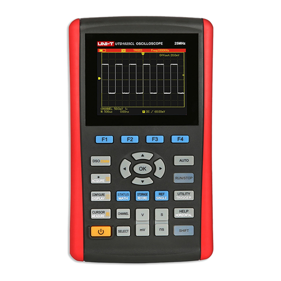
As shown in the following picture a the picture 3-3 compensation signal (1kHz 3V) output port on the Left side of the apparatus could be used to adjust the probe Picture Compensation Signal Output Picture 3-3 UTD1025CL Panel Connection of the Apparatus... - Page 15 UTD1000L User Manual Power key to power on off oscilloscope (DMM)mode, press the key to enter into the current ~ F1 F4:Key for menu option setting measurement menu MEASURE/CURSOR/[R] (resistance : DSO/DMM key to switch between the measurement) key: under the oscilloscope mode, working mode of oscilloscope(DSO) and press the key to enter COURSOR (sursor multimeter (DMM)
- Page 16 UTD1000L User Manual TRIGGER trigger setting)menu Press key SINGLE/REF key under the oscilloscope mode, press the key to set SINGLE(single trigger) SHIFT and press it again you can enter into the function Press key SHIFT and press it again UTILITY auxiliary function) menu. you can back to the REF(waveform reference) HORIZONTAL / HELP key under the menu...
- Page 17 UTD1000L User Manual “ ” , Press a vertical scale shall be relatively Direction key and OK key OK key used increased or reduced. to hide display the present menu bar : Selection key the selection for under normal circumstances under the switching channel vertical shift and trigger multimeter (DMM) mode, the keys are used to level shift under normal conditions...
-
Page 18: Chapter Iv Primary Application Of Oscilloscope
UTD1000L User Manual Interface Instruction Chapter IV Primary Application of Oscilloscope About the Chapter The chapter briefly introduces the UTD1025CL oscilloscope functions not in detail providing some basic examples for using menus and for basic operations Connect Appatatus to the Electricity... - Page 19 UTD1000L User Manual FFT represents adjusting the FFT operation SCAN oscilloscope collects and displays waveform waveform continuously under the scanning 2. Trigger coupling mode display are as follows: mode AC trigger coupling mode 5. Display time reading of trigger point to the DC trigger coupling mode center scale HF high frequency trigger coupling mode...
-
Page 20: Reset Oscilloscope
UTD1000L User Manual Status after factory setting: Reset Oscilloscope Function To reset the oscilloscope as factory setting, please Setting Acquire method operate under the following steps: Normal acquire “ ” s/div 1. Press key SHIFT the word shift would 1ms/div v/div 100mV/div appear on the right upper corner of the screen... -
Page 21: Menu Hiding
UTD1000L User Manual 2. All keys printed with two lines of words are Menu Hiding multifunctions, for acquiring the above functions, Press key OK to hide all key symbols and menu If “ ” please press key SHIFT the word shift shall need to display menu or key symbols, press it appear on the right upper corner of screen and again. -
Page 22: Probe Compensation
UTD1000L User Manual Picture 4-5 Home Computer Squarewave Signal Picture 4-4 Probe Multiplying Power Adjusting Probe Compensation 3. Connect probe with the output port of Connecting probe with channel for the first time compensation signal generator press key AUTO it is required to adjust probe compensation to and in few seconds the squarewave display match probe with the input channel The probe 1kHz,about 3Vpp,peak peak value will be seen... -
Page 23: Munual Set Vertical System Horizontal System And Trigger Level
UTD1000L User Manual 1. Set the attenuation coefficient of probe measuring the high voltage with the probe, please multiplying power as 10 firstly set the switch make sure that the insulated conductor of probe , on probe as 10 and connect probe with input is intact and do not touch the metal part of the channel of oscilloscope Connect probe pointer probe when connecting with the high voltage... -
Page 24: Horizontal System
UTD1000L User Manual - - . way of 1 2 5 Press left/right key to adjust horizontal positon of trigger point to observe more pretrigger information Picture 4-6 Vertical Shift of Waveform Notes: press key SELECT to change the function needed to adjust between channel vertical shift and Picture 4-7 Adjust Horizontal Time Base trigger level. -
Page 25: Automatic Setting Of Waveform Display
UTD1000L User Manual Automatic Setting of Waveform Display UTD1025CL oscilloscope has the automatic setting function Based on the input signal, it is possible to automatically adjust vertical deflection coefficient, scanning time base and trigger modes until the proper waveform display In application... - Page 26 UTD1000L User Manual “ ” 1. Press key SHIFT to show the character automatic trigger mode shall not be altered “ ” shift on the right upper corner of screen 2. Entering into the full automatic setting the 2. Press key AUTO to select starting full- following setting shall be compulsory automatic setting function and character A shall (1) Under the non main time base status it...
-
Page 27: Stop/Restore Data Collection
UTD1000L User Manual Stop Restore Data Collection Trigger Frequency Count Setting To operate under the following steps to stop data To operate under the following steps to open the collection trigger frequency count: Press key RUN/STOP the oscilloscope shall 1. Press key SHIFT character shift shall appear STOP data collection and trigger status on the on the right corner of screen upper part of screen shall display STOP... -
Page 28: Screen Brightness Adjustment
UTD1000L User Manual Screen Brightness Adjustment To operate under the following steps to adjust screen brightness: 1. Press key SHIFT to show character shift on the right corner of screen 2. Press key ACQUIRE to show backlight menu 3. Press key F1 to opern backlight adjustment box 4. -
Page 29: Store Bitmap
UTD1000L User Manual Store Bitmap To store bitmap under the following steps: 1. Press key SHIFT to show character shift on the right corner of screen 2. Press key OK to store bitmap into the inner memory of the apparatus Notes: to output bitmap into computer by the home computer software and to store it in the BMP... -
Page 30: Check Oscilloscope Status
UTD1000L User Manual Notes: press key AUTO the status information shall close automatically Picture 4-14 Single Trigger Check Oscilloscope Status Picture 4-15 Status Information To conduct online help under the following steps: 1. Press key SHIFT to show character shift on the right corner of screen 2. -
Page 31: Check Oscilloscope System Information
UTD1000L User Manual Check Oscilloscope System Information To check oscilloscope system information under the following steps: 1. Press key SHIFT to show character shift on the right corner of screen 2. Press key CONFIGURE to open interface configuration menu 3. Press key F4 the screen shall display informations such as: type, versionof the present oscilloscope. -
Page 32: Customization Parameter Measurement
UTD1000L User Manual 1. Press key MEASURE to show parameter Customization Parameter Measurement measurement menu To measure all customization parameters 2. Press key F1 the screen shall display automatically under the following steps: measuremen results of all parameters 1. Press key MEASURE to show customization parameter menu 2. -
Page 33: Smooth Waveform By Average Treatment
UTD1000L User Manual 3. Press key right left to select average frequency as and measurement results shall display times in average Picture 4-18Customization Parameters Menu Smooth Waveform by Average Treatment Picture 4-19 Average Treatment with 16 Times To smooth waveform under the following steps: 1. -
Page 34: Display Spike Pulse By The Peak Value Test Function
UTD1000L User Manual Display Spike Pulse by the Peak Value Use Persistence to Show Waveform You can use persistence function to observe Test Function dynamic signal continuously The function could be used to show results of 50 ns 1. Press key DISPLAY to show display mode menu or even wider pike pulse or other 2. -
Page 35: Select Ac Coupling
UTD1000L User Manual Select AC Coupling Reverse Polarity of the Displayed After resetting, the oscilloscope shall be DC Waveform coupling and screen shall display AC and DC To display input port waveform in opposite phase voltage To use AC coupling when want to observe under the following steps: a small AC signal loaded on the DC signal 1. -
Page 36: Automatic Setting For Small Signal With Dc Bias
The unique powerful automatic setting function of Connect signal with input channel, set channel UTD1025CL oscilloscope make it possible to coupling mode as DC, and conduct automatic complete quick correct automatic setting for setting, then the screen shall display the waveform signal containing any DC components under the shown as in the picture 4-24. - Page 37 UTD1000L User Manual Picture 4-25 AC parameter measurement Picture 4-24 Setting the Signal with DC Bias For trational oscilloscope, it is necessary to set it as AC coupling and measure signal s AC parameter set channel as DC manually adjust channel vertical scale coefficient and measure signal s DC parameter by the cursor, and get the test value finally as shown in following picture...
-
Page 38: Chapterv Use Multimeter
3 4-mm safety banana socket input ports for Picture 4-26 DC parameter measurement 、 、 multimeter: COM V/ Ω μ A/mA After comparison we can see UTD1025CL s One 10A CURRENT DIVIDER: UT-M07 quicker measurement speed and more intuitive Interface Indication Instruction measurement results Instructions: Battery indication 2. -
Page 39: Multimeter Measurement
UTD1000L User Manual AC voltage measurement Measure Resistance Value DC current measurement To measure resistance under the following steps: AC current measurement 1. Press key R the menu shall display the Resistance measurement measurement type resistance Diode measurement 2. Insert blace table pen into COM banana socket Continuity measurement input port and red one into Ω... -
Page 40: Measure Diode
UTD1000L User Manual Measure Diode To measure diode under the following steps: 1. Press key R the menu shall display the measurement type resistance 2. Press key F1 the menu shall display the measurement type diode 3. Insert blace table pen into COM banana socket input port and red one into Ω... -
Page 41: Measure Capacitance
UTD1000L User Manual 4. Connect the red and blace table pen with the input port and red one into Ω banana socket input port measured point when the measured point 4. Connect the red and blace table pen with the resistance is lower than 10 Ω... -
Page 42: Measure Dc Voltage
UTD1000L User Manual Measure DC Voltage Measure AC Voltage To measure DC voltage under the following steps To measure AC voltage under the following steps 1. Press key V the menu shall display the 1. Press key V the menu shall display the measurement type DC Voltage measurement type DC Voltage 2. -
Page 43: Measure Dc Current
UTD1000L User Manual Measure DC Current To measure DC current lower than 4mA under the following steps 1. Press key I and the menu shall display measurement type: DC current, measurement unit 、 、 μA. to select different range ( μA mA A) with the key F3... - Page 44 UTD1000L User Manual 4. Connect the red and blace table pen with the measurement socket and then insert the table measured point and the screen shall display the pen with the 10A CURRENT DIVIDER DC current value of the measured point 4.
-
Page 45: Measure Ac Current
UTD1000L User Manual Measure AC Current To measure AC current lower than 400mA under To measure AC current lower than 4mA under the the following steps following steps 1. Press key I and the menu shall display 1. Press key I and the menu shall display measurement type AC current measurement type AC current measurement 2. - Page 46 UTD1000L User Manual To measure AC current higher than 400mA under the following steps 1. Press key I and the menu shall display measurement type AC current 2. Press key F3 to set range as A and the measurement unit shall be A 3.
-
Page 47: Hold Measurement Value
UTD1000L User Manual Hold Measurement Value Relative Measurement You can hold the displayed reading antime. Relative measurement shall display the present 1. Press key RUN /STOP to hold the measurement results relative to the difined measurement value and character Hold shall reference value. -
Page 48: Select Automatic/Manual Range Adjustment
UTD1000L User Manual 5. Connect the red and blace table pen with the 2. Press key F2 to switch measurement mode, capacitor being measured and the screen shall and enter into manual measurement mode, menu display the capacitance reading of capacitor being display range mode manual measurend 3. -
Page 49: Chapter Vi Details About Using Oscilloscope
UTD1000L User Manual Chapter VI Details about Using Oscilloscope About the Chapter The chapter will introduce functions of UTD1025CL oscilloscope step by step and make detailed introduction about each function keys on the board and provide some basic examples for... - Page 50 UTD1000L User Manual Table 6-1 Pass AC and DC components of the input signal. Stop the DC components of the input signal. Coupling Ground Display DC level of the channel input port being equivalently grounded. Waverform Display channel waveform display Close channel waveform.
- Page 51 UTD1000L User Manual Vertical Shift of the Waveform When the channel triangle symbol is solid press up down key to shift channel waveform vertically Picture 6-3 Close Waveform Display Set Probe Multiplying Power To cooperate with the probe attenuation coefficient setting, it is required to set probe attenuation Picture 6-2 Vertical Shift of Waveform coefficient correspondingly in the channel...
-
Page 52: Horizontal Sysmem Setting
UTD1000L User Manual In the channel menu press key F3 to set probe Horizontal Shift of Waveform multiplying power. Press key left/right to adjust pretrigger depth. The Table for probe attenuation coefficient and trigger position generally is set at the screen corresponding menu settng horizontal center and you can see the 6 div Table 6-2... - Page 53 UTD1000L User Manual Picture 6-5 Screen Display after Window Extension Picture 6-4 Horizontal Setting Menu Two display sector in the window extension There are two function options in the horizontal function as shown in the above picture The upper setting menu: window extension and trigger part displays the original waveform after pressing holdoff.
- Page 54 UTD1000L User Manual has improved compared with main time base (as vary with it till the waveform display is stable as shown in picture 6-5). As waveform displayed by shown in the following picture the whole lower half part is corresponding to the upper half part sector, it is able to improve extension time base by adjusting key s~ns to reduce selected area thus increasing horizontal...
-
Page 55: Trigger System Setting
UTD1000L User Manual Trigger System Setting Trigger decides when to start collecting data and displaying waveform for oscilloscope If trigger has been set correctly, it shall transform the unstable display into meaningful waveform. In collecting data, the oscilloscope shall collect enough data to draw wavefrom on the left of trigger point. - Page 56 UTD1000L User Manual Table 6-3 Pulse width trigger: trigger will occur when the Instruction Function menu pulse width of trigger signal reaches set conditions. Set general trigger Vedio trigger: to trigger in the vertical or horizontal Trigger Type Common set options signal of standard vedio signal Set CH1 as information...
- Page 57 UTD1000L User Manual Notes: Table 6-4 Instruction Function menu General setting menu can also set by shortcut Set trigger type as edge ways, as shown in the following steps: Trigger Type Edge trigger. 1. Press key SHIFT and character shift shall Set trigger on the signal Rise appear on the right upper corner of screen...
- Page 58 UTD1000L User Manual Table 6-5 Vedio Trigger Instruction Function menu Select vedio trigger and trigger on the vertical or Set trigger type as edge horizontal line of NTC or PAL standard vedio Pluse width Trigger Type trigger. signal. Set positive pulse width Positive Pulse width as the trigger signal...
- Page 59 UTD1000L User Manual Tabel 6-6 Instruction Function menu Vedio Set trigger type as vedio trigger Trigger Type Vedio signal applicable to PAL system Standard NTSC Vedio signal applicable to NTSC system. All lines Set vedio horizontal trigger sync Sync vedio odd field Odd field Set to trigger sync on the Even field...
- Page 60 UTD1000L User Manual Slope Trigger Select slope trigger, and produce trigger when signal rising or falling velocity meets set value conditions. Picture 6-13 the Second Page of Trigger-Slope Trigger Picture 6-12 the First Page of Trigger-Slope Trigger...
- Page 61 UTD1000L User Manual Tabel 6-7 Instruction Function menu Set trigger type as slope trigger. Trigger Type Slope Select a threshold between the rising edge of trigger signal Rise Slope Select a threshold between the falling edge of trigger signal Fall ﹥...
- Page 62 UTD1000L User Manual or slower time base oscilloscope shall enter Terms explanation into SCAN mode 1. Trigger Source: trigger information source is ■ Normal trigger: oscilloscope shall collect the input channel CH1. ■ waveform under normal trigger mode only Input Channel: the commonly used channel trigger conditions have been met When there is information source is input channel...
-
Page 63: Collection Mode Setting
UTD1000L User Manual ■ “ ” stop DC component and attenuate Collection Mode Setting signal lower than 10HZ Press key ACQUIRE to enter into collection mode ■ High frequency restriction: attenuate high menu as shown in the following table frequency components over 80kHz Table 6-8 pretrigger/delay trigger: data collected... -
Page 64: Display Set
UTD1000L User Manual Notes: noise seems louder 1. Select acquisition mode to observe single Average mode: under the mode, oscilloscope will signal acquire several waveforms to calculate average 2. Select peak value test mode to observe value and display waveform finally thus envelop of signal to avoid confusion reducing random noise 3. - Page 65 UTD1000L User Manual Table 6-9 Instruction Function menu Indicate relative relations between vertical voltage and horizontal time. Format in the way of linking points Display acquisition Vectors Types points Display acquisition points directly Set mesh display mode in the waveform display area full Full Graticule Grid...
-
Page 66: Parameter Measurement Setting
UTD1000L User Manual Nouns explanation: Parameter Measurement Setting Display types: sector display will fill in blanks The following introduction shall help you to know between adjacent acquisition points during more about the powerful automatic display and point display shall only display measurement function of oscilloscope Press acquisition point key MEASURE to open parameter measurement... - Page 67 UTD1000L User Manual T able 6-10 Example 1: display all measurement values of channel. Measurement steps are as follows: Instruction Function menu Display measurement 1. Press key MEASURE to open parameter value of all parameters measurement menu All parameters Close automatic 2.
- Page 68 UTD1000L User Manual Example 2: to display channel peak peak value indicating the parameter has been customized amplitude under the following steps successfully and will appear on screen 1. Press key MEASURE to open parameter concurrently measurement menu 7. Press F2 to close customization parameter 2.
- Page 69 UTD1000L User Manual Picture 6-18 Amplitude Parameter Customizations Picture 6-19Amplitude Parameter Customizations Notes: Designated parameters are used for quick parameter measurement There are 19 types of measurement parameters and generally user just need to measure some of them and set as customization parameter instead of all.
- Page 70 UTD1000L User Manual Automatic measurement of parameter Base value (Vbase): voltage value from waveform base to GND (ground) Middle value (Vmid) half of amplitude value Peak peak value (Vpp): voltage value from waveform highest point to the lowest point Amplitude value (Vamp): voltage value from waveform top to bottom Overshoot: ratio of difference between waveform maximum value and top value with amplitude value...
-
Page 71: Storage And Record
UTD1000L User Manual pulse is at 50% amplitude Rise delay: delay time of A to B rise edge Fall delay delay time of A to B fall edge Positive duty ratio: ratio of positive pulse width with period Negative duty ratio ratio of negative pulse width with period Storage and Record Record Function... - Page 72 UTD1000L User Manual Picture 6-22 Waveform Record Menu Picture 6-23 record file storage menu Table 6-11 Record Menu Instruction Function menu Open/close waveform Rec Op... Record record function - - - - Play Play recorded waveform files - - - - Stop Stop the waveform files being recorded or played...
- Page 73 UTD1000L User Manual Table 6-12 record file storage menu 1. Press key RECORD to enter into waveform Instruction recording menu Function menu 2. Press key F1 to select menu function as record Open/close waveform Rec Op... Savec recording function 3. Press key F4 to start recording and press key “...
-
Page 74: Storage Function
UTD1000L User Manual For example: it is required to callbacke waveform recorded file that saved into inner memory in the example 1 to oscilloscope and playback 1. Press key RECORD to enter into waveform record menu 2. Press key F1 to select menu function as store 3. -
Page 75: Callback Function
UTD1000L User Manual In the storage memu, set as follows: Table 6-13 Instruction Function menu Setting Store sets in oscilloscope present menus Type wave Store waveform of channel. Select storage position Location 1-20 with left/ right key Save as the former selected --- - Save Picture 6-25... - Page 76 UTD1000L User Manual For example: it is required to save channel waveform into oscilloscope and callback. Waveform storage 1. Press key SHIFT and character shift will appear on the right upper corner of screen 2. Press key STORAGE to enter into waveform storage setting menu 3.
-
Page 77: Cursor Measurement
UTD1000L User Manual 8. Press left right key to select storage position Voltage/time measurement method: when cursor as 1 1or 2 appear at the same time adjust cursor 9 Press key F3 to callback, Load Success position with the up down left right key and indicated on screen means callback successful and press key SELECT to select cursor Reading waveform shall appear on screen... - Page 78 UTD1000L User Manual Table 6-15 Instruction Function menu Cursor used to measure Types Time time Independent To shift any one of two cursors independently Modes Tracking To shift two cursors concurrently,maintaining Δt Measurement parameter is Second time Cursor Units Picture 6-29 Voltage Cursor Measurement Menu Measurement parameter is frequency To select shift target as...
-
Page 79: Interface Set
UTD1000L User Manual Table 6-16 Interface Set Instruction Function menu To set oscilloscope display interface under the Cursor used to measure Types Amplitude following steps voltage 1. Press key SHIFT and character shift will Independent To shift any one of two appear on the right upper corner of screen cursors independently Modes... -
Page 80: Auxiliary Function Set
UTD1000L User Manual Table 6-17 Auxiliary Function Set Instruction Function menu To set oscilloscope display interface under the Select menu language following steps: Multi-lingual Language types 1. Press key SHIFT and character shift will appear on the right upper corner of screen Classic, 2. -
Page 81: Mathematic Operation Function
UTD1000L User Manual Major instructions: Mathematic Operation Function Self-correction: it can correct oscilloscope- Mathematic operation function is used to display produced measurement error resulted by operation results of channel waveform FFT environmental changes, you can operate the To conduct mathematic operation under the program based on need. - Page 82 UTD1000L User Manual ● Table 6-19 Measure harmonic content and distortion Instruction ● Function menu Indicate noise property in DC power Open/close FFT ● Analyze vibration operation function. FFT operation techniques Select information source Source As signal containing DC component or bias will involved in operation - - - - result in mistakes or bias in FFT waveform...
- Page 83 UTD1000L User Manual Table 6-20 Characteristics Fittest contents for measurement FFT window Compared with rectangular window it has good frequency Sine, period and narrow band random noise. Hanning resolution and inferior amplitude resolution Transient or short pulse, signal level varies greatly Frequency resolution before/after it.
-
Page 84: Automatic Set
UTD1000L User Manual Nouns explanations: Automatic Set FFT resolution: it is the quotient of acquisition and It is used to simplify operation. Press key , the operation point. When operation point count is oscilloscope will adjust vertival bias coefficient and fixed, the lower the acquisition rate is the better horizontal time base gear based on the amplitude the FFT resolution is... -
Page 85: Chapter Vii Troubleshooting
If it fails to start again, please contact 1. Check if probe is in normal connection with with UNI-T and we will serve you signal connection line Oscilloscope Shuts Down Several 2. - Page 86 UTD1000L User Manual 2. Check trigger type the common signal shall After Select Opening Average use edge trigger mode and vedio signal vedio Acquisition Method Time, Display trigger mode Waveform will display stably only Speed Slows Down: with correct trigger mode 1.
-
Page 87: Chater Viii Service And Support
3. Software version of the program upgradation Preparations before Upgradation: package shall be bigger than or equal to that of 1. Own an UTD1025CL oscilloscope produced by the present oscilloscope UNI T and acquire the type hardware and Program Upgradation software vision information of the present 1.Install the home computer software in disk... - Page 88 2. Copy the prepared program upgradation package (with suffix .upp) into the computer. The program upgradation package shall be acquired by downloading from UNI-T official website and from UNI-T market department. 3. Connect oscilloscope with computer by USB wire and open the home computer software...
- Page 89 UTD1000L User Manual → 4. by selecting option Operate Program 5. After upgradation oscilloscope display shall Upgradation in home computer software menu appear indication upgradation successful No select the program upgradation package copied operation to the oscilloscope at the moment, and into computer oscilloscope program starts restart it, the program upgradation is completed “...
-
Page 90: Chapter Ix Appendix
Acquisition rate shall apply to probe with attenuation switch being Acquisition, peak peak test, average Acquisition set 10 and UTD1025CL series of digital All channels reach N times of oscilloscope Digital oscilloscope reaches those acquisition concurrently and N Average value 、... - Page 91 UTD1000L User Manual Input Horizontal Direct current, alternative current, Waveform Input coupling sin(x)/x 、 、 ground AC GND interpolation 1 2%ΜΩ,connect with 20 3PF 3.5M Record length Input impedance in parallel Storage depth Probe attenuation Scanning sope 10ns/div-50s/divWith 1-2-5 1X,10X,100X,1000X coefficient setting (S/div) system...
- Page 92 UTD1000L User Manual Vertical bit resolu Analogue digital transformer A/D tion V/div Deflection coefficient ~ port 5mV/div 20V/div at the input BNC V/div scope ~ ~ ~ Shift sope 5mV/div 100mV/div: 1.2V;200mV/div 1V/div: 24V;2V/div 20V/div: 240V 25MHz Analogue bandwidth Single bandwidth 25MHz Low frequency response( ≤...
- Page 93 UTD1000L User Manual Oscilloscope Pulse width trigger ﹥,﹤,﹦ , positive pulse width Trigger Trigger mode ﹥,﹤,﹦ ≤ 1div negative pulse width Trigger sensitivity To screen center 10div 20ns-10s Trigger level scope Pulse width scope Normal mode/scanning mode, Vedio trigger Pretrigger ability pretrigger/delay trigger pretrigger Trigger sensitivity 2divs peak-to-peak value...
- Page 94 UTD1000L User Manual measurement Voltage difference between cursors( ΔV ),time difference between cursors( ΔT Manual mode Cursor Reciprocal of ΔT (Hz) ( 1/ΔT Automatic Allowable to display cursor in automatic measurement. measurement mode Measurement includes: Peak peak value, amplitude value, maximum value, minimum value,top value, bottom value, medium value, , average value, mean Automatic measurement square root value, overshoot, preshoot, frequency, period, rise time, fall time,...
- Page 95 UTD1000L User Manual Multimeter DC current: The accuracy of all measurements is within Maximum input DC current: DC 10A ± ( + ℃ ℃ ℃ %ofreading number of counts from15 to 25 Range Accuracy + ℃ ℃ 1.2% 5 character Add 0.1 (specific accuracy) for each below15 μA ℃.
- Page 96 UTD1000L User Manual Resistance 75Ω buzzer remain silent Good circuit connection, on-resistance value is: ≤10Ω buzzer Range Accuracy sounds continuously 400.0 Ω Display 4.000kΩ + 3.5inch TFT crystal display 40.00kΩ 1.2% 5 character Display types 320 horizontal 400.0kΩ Display resolution vertical picture element (display) 4.000MΩ...
- Page 97 UTD1000L User Manual Power Mechanic specifications 100~220 V AC rms,45~440Hz Dimension Power voltage 199mm 118mm 49mm (reference data) Output voltage 4000mA Weight Exclusive of package 0.9kg Output current (net weight) Inclusive of package 2.3kg Battery: 7.4 V, 3600mA rechargeable lithium ion battery with more than 8 hours power supply.
-
Page 98: Appendix B Maintenance And Cleaning
UTD1000L User Manual instead of any corrosive chemical detergent which Appendix B Maintenance and might damage the instrument or probe. Cleaning : Warning Before using the apparatus after being General Maintenance powered on again, please confirm that it has been Please do not store or put the instrument on the dry, guarding against the electric short circuit place where the monitor would be exposed to... - Page 99 UTD1000L User Manual Supply power by the battery, the battery indicator Replace lithium ion battery on the top of screen indicates the usage of Usually it is unnecessary to replace batteries, if quantity Five battery signals it shall be replaced by the qualified electricity necessary Of which...
- Page 100 UTD1000L User Manual This user manual may be revised without prior notice.
- Page 101 Rm 901, 9/F, Nanyang Plaza, 57 Hung To Road, Kwun Tong, Kowloon, Hong Kong Phone:(852) 2950 9168 Fax:(852) 2950 9303 Email:info@uni-trend.com Website:www.uni-trend.com Manufacturer: UNI-T Technology (Chengdu) Co., Ltd Add: 2F, Building D2, No.199, West District Avenue, West High-tech District, Chengdu City, Sichuan Province, P.R.China...
Need help?
Do you have a question about the UTD1025CL and is the answer not in the manual?
Questions and answers