Table of Contents
Advertisement
Quick Links
Advertisement
Table of Contents

Subscribe to Our Youtube Channel
Related Manuals for UNI-T UTD2000M


Summary of Contents for UNI-T UTD2000M
- Page 1 UTD2000CM User Manual...
- Page 2 ...
- Page 3 UTD2000M User Manual ● Copyrights reserved by Uni‐Trend Technology (China) Limited. ● Products under the brand name of “UNI‐T” are subject to the patent rights protection by China or other countries, including those whose patents have acquired or those pending. ● The company reserves its right to change product specification or product price. ● All rights reserved by UNI‐T. The licensed software products that are owned by UNI‐T or its subsidiary companies or specific providers are being protected by the State Copyright Law or International Treaties. The information contained in this Manual shall substitute all the corresponding information on materials published previously. UNI‐T is a registered trademark of Uni‐Trend Technology (China) Limited. ...
- Page 4 ...
- Page 5 UTD2000M User Manual This warranty is drafted by UNI‐T for the use of the product only and is buyer’s sole and exclusive remedy which is in lieu of all other warranties, express or implied, including but not limited to any implied warranty of merchantability or fitness for a particular purpose. UNI‐T or its authorized distributor shall not be liable for any special, indirect, incidental or consequential damages or losses, regardless of whether or not they have been notified of such possibilities. ...
- Page 6 ...
- Page 7 UTD2000M User Manual Maintain appropriate ventilation Do not operate in damp environment. Please do not operate in flammable or explosive environment. Keep unit surface clean and dry Safety Terms and Symbols Terms in the manual Following terms may appear in this Manual: Warning: “Warning” specifies conditions and actions that may pose life‐threatening hazards to the user. Caution: “Caution” identifies conditions and actions that may cause damage to the product or other properties. Terms on the product: Following terms may show on the product: DANGER indicates you are exposed to a potential hazard that may bring immediate damage to you as you read the marking. WARNING indicates you are exposed to a potential hazard that may not bring immediate damage to you as ...
- Page 8 ...
- Page 9 UTD2000M User Manual Introduction to UTD2000CM Series Digital Storage Oscilloscope UTD2000CM Series Digital Storage Oscilloscope is a perfect combination of user‐friendliness, excellent technical indexes and multiple functional features. A unit that can help users to complete their measurement work faster. This Manual contains information for the following 8 models of this series of digital storage oscilloscope Model Bandwidth Real‐time Maximum sampling rate memory depth UTD2042HM 40MHz 1GS/s 16Mpts UTD2042CM 40MHz 1GS/s 32Mpts UTD2062HM 60MHz 1GS/s 16Mpts UTD2062CM 60MHz 1GS/s ...
- Page 10 ...
-
Page 11: Table Of Contents
UTD2000M User Manual Table of Contents Table of Contents ................................11 Chapter 1 User Guide ................................13 1.1 Preliminary Understanding of the Unit’s Front Panel ..................13 1.2 Initial Settings ..............................15 1.3 General Check ..............................15 1.4 Probe Compensation ............................16 1.5 Run Auto Calibration Program ........................... 17 1.6 Auto Setup for Waveform Display ........................17 ... - Page 12 ...
-
Page 13: Chapter 1 User Guide
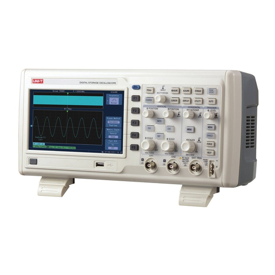
UTD2000M User Manual Chapter 1 User Guide UTD2000CM Series Digital Storage Oscilloscopes are small sized and portable benchtop digital storage oscilloscopes that offer convenient and user‐friendly front panel for basic measurement. This chapter will illustrate how to conduct the followings operations: △General check △Functional check △Probe compensation △Auto setup for waveform display △Preliminary understanding of vertical system △Preliminary understanding of horizontal system △Preliminary understanding of trigger system 1.1 Preliminary Understanding of the Unit’s Front Panel Once you have the Unit in hand, first, you need to understand its front panel. This chapter provides brief description and introduction of the operation and functions of the front panel of UTD2000CM series instruments, so that you may get familiar with the operation of UTD2000CM Series Digital Storage Oscilloscope. ... - Page 14 ...
-
Page 15: Initial Settings
UTD2000M User Manual multi‐functional knob may be turned to do setup and to make the choice. MEASURE: For auto waveform measurement; ACQUIRE: Set sampling mode; STORAGE: Save a waveform to or load a waveform from memory or U Disk; CURSOR: Activate the cursor for manual cursor measurement; DISPLAY: Set wave format and type; UTILITY: Activate system tools, i.e. system configuration; HORIZONTAL MENU: Set window expansion and trigger hold off; TRIGGER MENU: Adjust the parameter for triggering part; ... -
Page 16: Probe Compensation
... -
Page 17: Run Auto Calibration Program
UTD2000M User Manual Warning: To avoid electrical shock when probes are used in measuring high voltage, please ensure that their insulated wire is in good condition and do not touch any metal part of them when they are connected to high voltage source. Remark: When the “attenuation” switch of the probe is turned to 1×, the bandwidth of this instrument will be limited by the probe to 6MHz. In order to use its full bandwidth, please ensure that the switch has been turned to 10×. 1.5 Run Auto Calibration Program Running auto calibration program can realize the best accuracy of instrument. You can run this operation at any time. But it is a must whenever the changes in ambient temperature reaches 5℃ or more. To run auto calibration program, please follow the following steps. 1. Disconnect all probes or power cables from the channel’s input connector; 2. Press UTILITY key; 3. Press F1 key to select “system configuration” displayed at the right of the displayer; 4. Press F1 key to select “auto calibration program”; 5. Press multi‐function knob to confirm the execution of auto calibration program, and it may take several minutes to complete this process. ... -
Page 18: Preliminary Understanding Of Horizontal System
... -
Page 19: Preliminary Understanding Of Trigger System
UTD2000M User Manual Fig. 1‐5 Horizontal Control Area Shown on the Front Panel Turn the “POSITION” knob (for movement) to move the horizontal position for all channels and of REF waveforms, which will return to median swiftly once this knob is pressed down. MENU for horizontal menu, display window and hold off “SCALE” is used to set the scale coefficient for horizontal time base ‐ “SEC/DIV”. Press this shortcut for quick access into window expansion screen. When “window expansion” is enabled, this can also be used to adjust windows scale and amplification factor. 1. Use horizontal “SCALE” knob to change the setup of horizontal time base range and observe the change of status information. Turn horizontal “SCALE” knob to change time base range – “SEC/DIV”, and you may notice from the status bar the corresponding change of the display of corresponding time base range, in detail, the horizontal scan rate has been changed from 2ns/div~50s/div, stepping in the form of “1‐2‐5”. 2. Use horizontal “POSITION” knob to adjust horizontal position of the signal in waveform window. While the horizontal “POSITION” knob is being turned, waveform can be observed moving in horizontal direction. Press down the horizontal “POSITION” knob to return the trigger point to horizontal median. 3. Press MENU key to display “Zoom” menu. Under this menu, press F3 to open “expanded window”, then press F1 to shut off the “expanded window” and return to main window. Under this menu, “MULTI PURPOSE” knob can also be turned to set “trigger hold off” ... -
Page 20: Chapter 2 Instrument Settings
... -
Page 21: Waveform Brightness Settings
UTD2000M User Manual ■Displaying Mode Settings (DISPLAY) ■Storage and Load (STORAGE) ■System Settings (UTILITY) ■Auto Measurement (MEASURE) ■Cursor Measurement (CURSOR) ■Select & Start Key (AUTO, RUN/STOP) ■Multi‐purpose Key (MULTIPURPOSE) You are suggested to read this chapter carefully so as to understand the multiple measurement function and system operation of UTD2000CM series instruments. 2.1 Waveform Brightness Settings You can adjust the waveform brightness by using “MULTIPURPOSE” knob after opening CH1 or CH2. Press DISPLAY to open DISPLAY menu. Press F5 to select “waveform brightness setting menu”, then change waveform brightness using “ MULTIPURPOSE ” knob. Figure 2‐1 Waveform Brightness Settings ... -
Page 22: Channel Coupling Settings
... - Page 23 UTD2000M User Manual Fig. 2‐2 DC Component in a Signal has been Blocked Press F1 and then press F1 to select DC 1MΩ, whose channel coupling is set as DC coupling mode. Thus it allows the passage of both AC and DC components contained in the signal under test, which is input to CH1. Waveform display is shown as below. DC Coupling Settings Fig. 2‐3 Both the AC and DC Components in a Signal have been Displayed Simultaneously Press F1 and then press F3 to select grounding as the channel coupling mode. Thus both AC and DC components contained in the signal under test are blocked. Waveform display is shown as below. Under this mode, though no waveform is being displayed on the screen, the input signal still maintains connection with the channel circuit. Earth Coupling Settings Fig. 2‐4 Both the AC and DC Components in a Signal have been blocked Simultaneously ...
-
Page 24: Channel's Bandwidth Limit Setting
... - Page 25 UTD2000M User Manual coefficient should be set in operation menu of the channel, i.e. in order to ensure correct voltage readings, if the probe attenuation coefficient is 10:1, then the probe coefficient in channel menu should be set as 10× accordingly, and the rest can be inferred like this. Below is an example showing the setting and vertical range for probe with an attenuation coefficient of 10:1. Probe attenuation coefficient Fig. 2‐7 Probe Coefficient Setting in Channel Menu Apart from setting a predefined amplification factor of 1×, 10×, 100× and 1000×, it also allows users to set desired coefficients that suit to specific applications. Normally, the probes of oscilloscope are voltage probes. However, this instrument also allows us to set probes as current ones in order to meet different measurement needs. Detailed settings are shown below. ...
-
Page 26: Vertical Scale Coefficient (Volts/Grids) Settings
... -
Page 27: Bias Voltage Setting
UTD2000M User Manual Reversed phase Fig. 2‐11 A Phase Reversed Waveform 2.2.6 Bias Voltage Setting It becomes inconvenient to observe waveform when the amplitude of DC component in a signal under test is very large relative to the amplitude of AC component in that signal, as shown in Fig. 2012. Fig. 2‐12 Signal Containing DC Component Then we can use bias voltage function to offset the DC component in a signal, so that the signal can be displayed better on the screen. Once we enter into the functional menu of bias voltage, we can set bias voltage by turning MULTIPURPOSE knob. As shown in Fig. 2‐13, we can calculate the DC component of a signal with the use of bias voltage. ... -
Page 28: Realization Of Mathematical Function
... - Page 29 UTD2000M User Manual ÷ Operator 1÷Operator 2 Operand 2 CH1 Set operand 2 as the waveform in CH1 CH2 Set operand 2 as the waveform in CH2 Scale 1/1 Scaling the waveform as per a scale, totally, there are 1/10 four scales: 1/1, 1/10, 1/100, 1/1000 1/100 1/1000 FFT Spectrum Analysis Using FFT, we can change time domain signal (YT) to frequency domain signal. It allows us to observe the following types of signal conveniently with the use of FFT. ● Harmonic content and distortion in measuring system ● Express noise characteristic in DC power ● Analyzing vibration Fundamental component 1kHz ...
- Page 30 ...
- Page 31 UTD2000M User Manual Definition FFT Resolution: it is defined as the quotient of a division between sampling rate and operating points. In case of a fixed operating points, the lower the sampling rate, the better the FFT resolution. Nyquist frequency: For a waveform with the maximum frequency of f, the original waveform can only be built with the use of a sampling rate that is at least 2f. This is also referred to as Nyquist Code. The “f” here is Nyquist frequency, while the “2f” is Nyquist sampling rate. Digital Filtering Function Fig. 2‐16 Digital Filtering Table 2‐5: Digital Filtering Menu Menu Setting Description Type ...
-
Page 32: Reference Waveform
... - Page 33 UTD2000M User Manual waveform relative to center of the screen. The change of horizontal position equals to the change of position relative to trigger point of a waveform. Horizontal Position: Adjust the horizontal position of a waveform in channel (including mathematical calculations). The resolution of this control key changes with the time base. Horizontal Scale: Adjust the horizontal position of a waveform in channel (including mathematical calculations). The resolution of this control key changes with the time base. Horizontal Scale: Adjust the main timebase, which is “SEC/DIV”. When the “extended time base” is opened, the window width can be changed by turning horizontal scale knob to change delayed scan time base. ...
-
Page 34: Trigger System Settings
... -
Page 35: Edge Triggering
UTD2000M User Manual to acquire signal baseline so as to confirm whether the acquisition is normal; After pressing SINGLE key to set single trigger, FORCE (force trigger) key can be pressed to execute experimental acquisition so as to check the control settings. Trigger Control MENU Trigger Type: Edge, Pulse width, video, slope, less amplitude pulse, alternative Edge Triggering: Trigger occurs when the edge of a triggering signal reaches a given level. Pulse Width Triggering: Trigger occurs when the pulse width of a triggering signal reaches a preset triggering condition. ... -
Page 36: Pulse Width Triggering
... -
Page 37: Video Triggering
UTD2000M User Manual > Trigger occurs when the pulse width of an input signal is larger than the preset pulse width time; = Trigger occurs when the pulse width of an input signal equals the preset pulse width time; Pulse Width Time 20.0ns~10.0s 20.0ns~10.0s; Trigger pulse width is set between 20.0ns~10.0s using “MULTIPURPOSE” knob Return —— Return to “pulse width triggering” menu 2.4.3 Video Triggering Once video triggering is selected, it allows triggering occurs at the field or row of a standard video signal in NTSC or PAL format. Trigger coupling is preset to be DC. See below table for menu introduction. Table 2‐11 Video Triggering ... -
Page 38: Slope Triggering
... -
Page 39: Less Amplitude Pulse Triggering
UTD2000M User Manual = Set to trigger when slope at edge is smaller than a preset value; Set to trigger when slope at edge equals a preset value; Time Setup 20ns~10s Set slew rate time Low Level Set a threshold level for low level, a signal with low Threshold value High Level level must be smaller than the preset value; Set a threshold level for high level, a signal with high High and Low level must be higher than the preset value; ... -
Page 40: Trigger Hold Off Settings
... - Page 41 UTD2000M User Manual Fig. 2‐23 Trigger Hold off for Synchronization of Complicated Waveforms Operational Instructions 1. Firstly, we use the method for the synchronization of normal signal, which is to select “edge” and “trigger source” from “trigger menu”, and adjust trigger level, thus trying the best to stabilize the waveform display. 2. Press horizontal MENU key to display horizontal menu. 3. Change the hold off time by turning “MULTIPURPOSE” knob located on the upper part of the unit panel till the waveform display has been stabilized. Operation Skills: Normally, the hold off time is slightly less than the time of “major cycle”, i.e. when observing the waveform for RS232 communication signal, if the hold off time is set to be slightly more than the edge starting time of each frame of data, it will be easier to observe. ...
-
Page 42: Sampling System Settings
... -
Page 43: Acquiring Mode
UTD2000M User Manual Table 2‐14 Sampling Menu Menu Setting Description Acquiring Mode Normal Normal sampling mode Sampling Peak detection mode, which is used to detect burrs and to reduce Peak Detection the possibility of having false waveform; Average Set average sampling mode and display average times; High Resolution Set high resolution display; Sampling Mode Equivalent It requires multiple times of repeated sampling before acquiring Real time the sampling data needed to form a waveform; Acquiring all data needed to form a waveform during a single triggering. Memory Depth ... - Page 44 ...
-
Page 45: Sampling Mode
UTD2000M User Manual Notes: UTD2202HM&CM has no “high resolution” setting in terms of acquiring mode. 2.5.2 Sampling Mode If the time base falls in between 20ns/div and 2ns/div, the data being displayed then has exceeded the sampling rate of 1GS/S, so equivalent sampling mode should be adopted to perform repeat sampling in order to acquire the sample data required for the display of a waveform. 2.5.3 Memory Depth If users intend to observe more details of a waveform, they are suggested to use “deep memory”, which provides them with details of waveforms under expanded window, and will not cause failure to see details of a waveform due to the larger frequency it has. Under deep memory mode, the window can be expanded to 10000 times, whereas in normal mode, this figure is only 10. See blow Fig. 2‐21 and Fig. 2‐22. ... -
Page 46: Fast Sampling
... - Page 47 UTD2000M User Manual Fig. 2‐30 Waveform with Fast Sampling on Notes: To see more details of a waveform, please use “deep memory”. To capture some abnormal signal, please use “fast sampling mode”. For single channel, fast sampling is effective only for a sampling rate between 1ms/div and 100ns/div, while for dual channel, fast sampling is effective only for a sampling rate between 1ms/div and 200ns/div. Definitions Real‐time Sampling: one time sampling of all data needed. The highest real time sampling rate of unit is 1GS/s. Normal Mode: “Normal Sampling Mode” can be used in any time base for fastest sampling. Normal Mode is the default model. Peak Detection Mode: Under this acquiring mode, oscilloscope picks up both the maximum and minimal values within each sampling interval of an input signal and then use these values for waveform displaying. In this way, it allows an oscilloscope to acquire and display narrow pulse. Otherwise, these narrow pulses would have been ...
-
Page 48: Display System Settings
... -
Page 49: Storage System Settings
UTD2000M User Manual size and shape of XY graphic can be adjusted via “SCALE” knob for both channels. Changing time base can acquire a Lissajous pattern with good displaying effect. With its unique X‐Y display mode, it can display waveform in a channel and X‐Y Lissajous pattern simultaneously. In addition, this series of units also have following functions, for example, Auto Measuring Function Cursor Measuring Function Reference or Mathematical Function Following Functions are not Effective under X‐Y Mode Window Expansion Function Horizontal “POSITION” knob Key Points Display Format: “Vector Display” will fill in the blank area between proximal sampling points, while “Point Display” only displays sampling points. Waveform Capture Rate: waveform capture rate refers to the waveform refreshing times per second and it impacts the unit’s capability to display the dynamic change of signal rapidly. ... - Page 50 ...
-
Page 51: Auto Measuring
UTD2000M User Manual 3、 Select “Bitmap” to enter into “Bitmap Exportation Menu”, see Table 2‐20 Remark: Bitmap format file can only be exported into a U‐disk. Table 2‐20 Bitmap Exportation Menu Menu Setting Description Bitmap —— Export the waveform being display into U‐disk in the format of bitmap. Export See Table 2‐21 Enter into USB menu Table 2‐21 USB Menu Menu Setting Description File Name —— Use both “MULTIPURPOSE” knob and “F1” key to set the name of the file, which is to be imported from U‐disk. Confirmation ... - Page 52 ...
- Page 53 UTD2000M User Manual then the screen will pop up a dialog box for customized parameter selection. 2. Make the selection by turning “MULTIPURPOSE” knob and then confirm the selection by pressing it down. Once you complete the selection of customized parameter, press F5 key to close the dialog box for customized parameter selection. 3. In case a certain measurement choice has to be cleared, i.e. “frequency”, follow the step 1 and select “frequency” from the popped up dialog box for customized parameter selection. Then the “frequency” listed to the bottom of the screen will be cleared. 4. Customized parameters allow the measurement of different channels at the same time. The method is that if CH1 is to be measured, press CH1 for once, then the color of measurement shown in the measurement dialog box turns to blue and all the measurement parameters selected are in blue fonts, see Fig. 2‐35. Likewise, press CH2 if the customized parameters are intended for the measurement of CH2, See Fig. 2‐36. ...
- Page 54 ...
- Page 55 UTD2000M User Manual energy equals to the converted energy which is generated by AC signal within a cycle. Area: The product of voltage and time for a waveform being displayed by the screen. CycArea: the product of voltage and time for a waveform being displayed by the screen during a cycle. Oversht: Ratio between the difference between “Max” and “High” and the amplitude. PreSht: Ratio between the difference between “Min” and “Low” and the amplitude. 2. Oscilloscopes with bandwidth more than 100MHz can auto measure the following voltage parameters: Vpp: the voltage value between the highest and the lowest points of a waveform. Vmax: The voltage value between the highest point of a waveform and GND. Vmin: The voltage value between the lowest point of a waveform and GND. Vamp: The voltage value between the top and the bottom of a waveform. Vmid: Half of the summed voltage value for “High” and “Low”. Vtop: The voltage value between the top of a waveform and GND. Vbase: The voltage value between the bottom of a waveform and GND. ...
-
Page 56: Cursor Measurement
... -
Page 57: Auxiliary Function Settings
UTD2000M User Manual adjust the positions of those two cursors separately, while under tracking mode, we can realize the simultaneous movement of the two cursors by pressing “SELECT” key. Table 2‐26 Time ‐ Cursor Measurement Menu Menu Setting Description Type Time Cursors are used to measure time ... - Page 58 ...
- Page 59 UTD2000M User Manual Run Restart “Pass/Fail” detection and count. Stop Condition See Table 2‐31 Set a threshold value for time of pass or fail and use it as a condition, when such condition is reached, count and “Pass/Fail” detection will be stopped automatically. Template Condition See Table 2‐32 Create a template condition for “Pass/Fail” detection. Return ‐‐ Return to function menu Previous Page —— Return to previous page Table 2‐31 Pass Detection (Stop Condition Menu) Menu Setting Description Stop Type ...
-
Page 60: The Use Of Key Lock
... -
Page 61: Auto (Auto Settings) Strategy
UTD2000M User Manual Function Open Lock Bandwidth Limit Full bandwidth Full bandwidth or maintain current settings of 20MHz. Vertical Scale Coefficient Adjust in accordance with signal Adjust in accordance with signal amplitude amplitude Volts/Grid Rough tuning Rough tuning Phase Reversed Close Open, close or maintain current settings Horizontal Position Auto Adjustment Auto Adjustment Second/Grid Adjust in accordance with signal Adjust in accordance with signal ... - Page 62 ...
-
Page 63: The Use Of "Run/Stop" And "Menu On/Off" Keys
UTD2000M User Manual 2.12 The Use of “RUN/STOP” and “MENU ON/OFF” Keys RUN/STOP Key On the upper right corner of the unit’s operation panel, there is a key, RUN/STOP, which, once pressed with green light on, shall indicate operation state, otherwise, if red light on, shall indicate stoppage. When in operation state, it indicates that the digital storage oscilloscope is acquiring waveform continuously, with an “AUTO” sign appearing on top of the screen. When in stoppage, the sign, “STOP” appears on top of the screen. This key switches waveform sampling between operation and stoppage. Menu ON/OFF Key Display or hide current menu ... -
Page 64: Chapter 3 Application Examples
... -
Page 65: Reduce Random Noise In A Signal
UTD2000M User Manual Operational Steps are the followings; 1. Set the probe and the attenuation coefficient of CH1 channel the same way as in the former case. 2. Set trigger settings. ①.Press MENU key located in the trigger control area to display trigger setting menu. ... - Page 66 ...
- Page 67 UTD2000M User Manual Fig. 3‐4 Signal Noise has been Rejected Notes: The use of average sampling makes waveform display and update slower, as well as having no persistence effect, which is a normal phenomenon. High Resolution Reduces Random Noise Average mode has certain defects: the use of average sampling makes waveform display and update slower, as well as having no persistence effect, which is inconvenient for operation under certain circumstance. However, high resolution well overcomes this issue. Average modes used by “average” and “high resolution” modes are not the same, with former being the “average based on multiple samplings” and the latter being the “average based on a single sampling”. Specific operations are: Press ACQUIRE key located on the menu area of the panel to display sampling setting menu. Press F1 key and then press “MULTIPURPOSE” knob to set sampling mode as “high resolution” and then “SELECT” to confirm. Below is a picture showing random noise has been reduced. ...
-
Page 68: The Application Of Cursor Measurement
... - Page 69 UTD2000M User Manual Fig. 3‐7 Use Cursors to Measure Negative Duty Ratio of Pulse 3. Measure phase difference of two signals Measure phase difference caused when a sine signal passes a circuit. In details, CH1 connects to the input signal of the circuit while CH2 connects to the output signal of the circuit. For the ease of measurement, displacements of CH1 and CH2 are set to the midpoints, as shown in Fig. 3‐8, and then following below steps to measure: 1. Press “CURSOR” key to display “cursor measurement menu”; 2. Press F1 key to open cursor measurement function; 3. Press F1 key again to set cursor type to be “time”; 4. Press F3 key to set the vertical unit as “phase”; 5. Use “MULTIPURPOSE” knob to move cursor 1 to the midpoint of the first rising edge of the pulse (the cross point with GND of the channel); 6. Press “SELECT” to select cursor 2, and then turn “MUTIPURPOSE” to move cursor 2 to the midpoint of the second rising edge of the pulse; 7. Press F4 and it displays “current position – 360°”, meaning to set△value between current cursor 1 and cursor 2 to 360°; ...
-
Page 70: The Application Of X-Y Function
... -
Page 71: Example Of Video Triggering
UTD2000M User Manual Fig. 3‐9 X‐Y Schematic Diagram Based on sinθ=A/B or C/D, among which,θis the angle of phase difference between channels. See above graphic for the definition of A, B, C and D. Hence we can conclude that the angle of phase difference,θ=±arcsin(A/B) orθ=±arcsin(C/D). If the principal axis of the ellipse is within quadrant I or III, then the angle of phase difference obtained should be within quadrant I or IV, that is within 0~π/2 or 3π/2~2π. If the principal axis of the ellipse is within quadrant II or IV, then the angle of phase difference obtained should be within quadrant II or III, that is within π/2~π or π~3π/2. In addition, if either the frequency or phase difference of the two signals under test is in integral multiple, the frequency and phase relation of the two signals can then be calculated based on the graphic. ... -
Page 72: Example Of Less Amplitude Pulse Trigger
... - Page 73 UTD2000M User Manual Less amplitude trigger can be used to trigger the pulse signal that has passed one trigger level but has failed to pass another one. Less amplitude triggering can only accept those triggers aroused by pulses within two prescribed amplitudes for both entry and exit. Following is the operation steps explained by taking a specific case as an example: 1、 Press MENU key located in the trigger control area to enter into trigger type menu; MULTIPURPOSE 2、 Then press F1 and use “ ” knob to select less amplitude pulse in the ejected menu, then press “SELECT” to confirm the selection; ...
-
Page 74: Use Of Storage Function
... - Page 75 UTD2000M User Manual Fig. 3‐14 Save Bitmap into a U‐Disk Save the Settings of this Instrument To save the measured waveform data into a U‐disk, following steps can be followed: 1、 Insert U‐disk into the USB‐HOST port located on the front panel of the oscilloscope; 2、Press STORAGE key and then press F1. Thereafter, use “MULTIPURPOSE” knob to select “Settings”; 3、While in waveform storage menu, press F5 to enter into USB menu; 4、Press F1 key and change the file name by turning “MULTIPURPOSE” knob. After press F5 for confirmation, the screen image will be saved to the root directory of the U‐disk successfully under the designated name. Save Waveform Data UTD2000CM series instruments also provide waveform storage function, which can be used to export data in CSV ...
-
Page 76: Pass/Fail Detection
... - Page 77 UTD2000M User Manual Fig. 3‐16 “Pass/Fail” Detection Setting (1) Fig. 3‐17 “Pass/Fail” Detection Setting (2) ...
-
Page 78: Use Updating Software Contained In A U-Disk
... -
Page 79: Chapter 4 System Message & Troubleshooting
UTD2000M User Manual Chapter 4 System Message & Troubleshooting 4.1 Explanation on System Messages Adjusting Limit Reached: It prompts that under current state, the adjustment gained through the use of the “MULTIPURPOSE” knob has reached its limit and that we should stop further adjusting. Such message appears when vertical scale coefficient knob, time base knob, horizontal and vertical displacement knobs and trigger level reach their adjustment limit. USB Device Installed Successfully: When a U‐disk is inserted into an oscilloscope, if successfully connected, this message appears on the screen. USB Device Removed: This message appears on the screen, when a U‐disk is removed from an oscilloscope. I/O Operation Failure: In case the communication with U‐disk is not successful or no document in the U‐disk is found to be in conformity with the requirements. Saving: This message appears on the screen with progress bar showing to its right when saving a waveform. 4.2 Troubleshooting 1.In case the oscilloscope still shows black screen (displaying nothing) when both the power and soft start switch are turned on, please follow the following steps to deal with it accordingly. ... - Page 80 ...
-
Page 81: Chapter 5 Service & Support
UTD2000M User Manual Chapter 5 Service & Support 5.1 Program Updating Contact marketing Department of UNI‐T or log into our website to obtain the latest program package, unzip the package and apply embedded program updating system to update the current program of your oscilloscope, making sure your unit enjoys the latest version of program released by UNI‐T. Preparations Before Updating 1、Find your oscilloscope and then acquire and record its model, hardware version and software version from the system information submenu of UTILITY menu. 2、Contact marketing Department of UNI‐T or log into our website to obtain the latest program package that is for oscilloscopes with identical model and hardware version. 3、Prepare a U‐disk (disk format is FAT or FAT32). After the obtained updating program package is unzipped, place the same to root directory of the U‐disk. The suffix of updating program is “uts”. ... - Page 82 ...
-
Page 83: Warranty Summary
UTD2000M User Manual 5.2 Warranty Summary Each product produced and sold by UNI‐T is warranted to be free from defects in material and workmanship under normal use and service. The warranty period is three years and begins on the date of shipment made by our authorized distributors. In case our product is proved to be defective within the warranty period, UNI‐T shall repair or replace it in accordance with detailed provisions set forth in the warranty. If you need our repair service or request the full content of this warranty, please contact the nearest UNI‐T sales or service center. This warranty is drafted by UNI‐T for the use of the product only and is buyer’s sole and exclusive remedy which is in lieu of all other warranties, express or implied, including but not limited to any implied warranty of merchantability or fitness for a particular purpose. UNI‐T or its authorized distributor shall not be liable for any special, indirect, incidental or consequential damages or losses, regardless of whether or not they have been notified of such possibilities. 5.3 How to Contact Us In case this product has brought you any inconvenience during your use of it, you may directly contact Uni‐Trend Technology (China) Limited if you are in mainland China. Contact Time: AM 8:00 to PM 5:30 (Beijing Time), from Monday to Friday or use Email to contact us. Our Email address is infosh@uni‐trend.com.cn For product support outside mainland China, please contact your local UNI‐T distributors or sales center. Extended warranty or calibration period are available to many of our products, for details, please contact your local UNI‐T distributors or sales center. To obtain the list of addresses for our service centers around the world, please visit our website: ... -
Page 84: Chapter 6 Appendix
... - Page 85 UTD2000M User Manual Horizontal Waveform interpolation sin(x)/x Bandwidth≤100MHz: Single Channel: Normal‐6kpts; Deep ‐32Mpts UTD2000CM Dual channel:Normal‐6kpts, Deep ‐16Mpts Bandwidth>100MHz: Single Channel: Normal‐6kpts; Deep ‐16Mpts Dual channel:Normal‐6kpts, Deep ‐ 8Mpts Memory Depth Bandwidth≤100MHz: Single Channel: Normal‐6kpts; Deep ‐16Mpts UTD2000HM Dual channel:Normal‐6kpts, Deep ‐8Mpts Bandwidth>100MHz: Single Channel: Normal‐6kpts; Deep ‐8Mpts Dual channel:Normal‐6kpts, Deep ‐4Mpts Waveform Capture Rate ≥150000wfms/s Horizontal Scale (s/div) 2ns/div~50s/div, stepping in 1‐2‐5 format ±50ppm(any time interval≥1ms) Sampling Rate & Delay Time ...
- Page 86 ...
- Page 87 UTD2000M User Manual Pulse Width Trigger >, <, = positive pulse width; >, <, = negative pulse Trigger Mode width Pulse Width Scope 20ns~10s Video Trigger Internal 2div Trigger Sensitivity (Video Trigger, Typical) EXT 400mV EXT/5 2.0v Signal format & Row/Field Support standard NTSC & PAL; Frequency (Video Trigger Type) Row number scope is 1‐525 (NTSC) and 1‐625 (PAL) Slope Trigger >, <, = positive slope; >, <, = negative slope ...
- Page 88 ...
-
Page 89: Appendix B: Accessories
UTD2000M User Manual Ambient Environment Operation: 0℃~+40℃ Temperature Non‐operation: ‐20℃~+60℃ Cooling Method Forced Cooling Provided by Fan 〈35℃:≤90%RH ,+35℃~+40℃:≤60%RH Humidity Operation: below 3,000 meters Height Non‐operation: below 15,000 Machinery Specification Width 330mm Dimension Height 155mm Depth 130mm G.W Package excluded 2.9kg (N.W) Package included 5.0kg IP Protection IP2X Calibration Frequency It is suggested to be calibrated every 1 year. ... -
Page 90: Appendix C: Maintenance & Cleaning
... - Page 91 UTD2000M User Manual System Function Factory Settings Vertical System CH1 5V/DIV CH2 5V/DIV Coupling Mode AC 1MΩ Bandwidth Limit Full Bandwidth Volts/Grid Rough Tuning Probe 1× Phase Reversed Closed Bias Voltage Closed Closed MATH、REF Horizontal System Expanded Window Closed Horizontal Time Base 500s/div Horizontal Displacement Horizontal Midpoint Trigger System Hold Off Time Minimal Value: 100.0000ns Trigger Type ...
- Page 92 ...
- Page 93 UTD2000M User Manual ...
- Page 94 ...
Need help?
Do you have a question about the UTD2000M and is the answer not in the manual?
Questions and answers