Table of Contents
Advertisement
Industrial
Hydraulics
Rexroth IndraControl VCP 20
Rexroth IndraControl VDP 16.1
Rexroth IndraControl VDP 40.1
Rexroth IndraControl VDP 60.1
Project Planning Manual
Electric Drives
Linear Motion and
and Controls
Assembly Technologies
Service
Mobile
Pneumatics
Automation
Hydraulics
R911307654
Edition 02
Advertisement
Chapters
Table of Contents

Subscribe to Our Youtube Channel
Related Manuals for Bosch Rexroth IndraControl VDP 16.1 Series


Summary of Contents for Bosch Rexroth IndraControl VDP 16.1 Series
- Page 1 Industrial Electric Drives Linear Motion and Service Mobile Hydraulics and Controls Assembly Technologies Pneumatics Automation Hydraulics Rexroth IndraControl VCP 20 Rexroth IndraControl VDP 16.1 R911307654 Edition 02 Rexroth IndraControl VDP 40.1 Rexroth IndraControl VDP 60.1 Project Planning Manual...
- Page 2 120-2100-B368-02/EN 02/05 First English Edition Copyright 2005 Bosch Rexroth AG © Copying this document, giving it to others and the use or communication of the contents thereof without express authority, are forbidden. Offenders are liable for the payment of damages. All rights are reserved in the event of the grant of a patent or the registration of a utility model or design (DIN 34-1).
-
Page 3: Table Of Contents
VDP 16.1, VDP 40.1 and VDP 60.1 Contents Contents System Presentation Brief Description VDP 16.1, VDP 40.1 and VDP 60.1..............1-1 Variants............................1-1 Distinguishing Features ......................1-1 Displays with Keypad ......................1-2 Displays with Touch Screen ....................1-2 Variants VDP 16.1 ........................1-3 Variants VDP 40.1 ........................ - Page 4 Contents VDP 16.1, VDP 40.1 and VDP 60.1 Dimensions Dimensions of the VDP Displays ....................5-1 Housing Dimensions VDP 16.1 ....................5-1 Housing Dimensions VDP 40.1 ....................5-4 Housing Dimensions VDP 60.1 ....................5-7 Housing Dimensions of the Y-Repeater ..................5-9 Installation...........................
- Page 5 VDP 16.1, VDP 40.1 and VDP 60.1 Contents Touch Screen Software 10 Ordering Information 10-1 10.1 Type Code ..........................10-1 VDP 16.1 ..........................10-1 VDP 40.1 ..........................10-2 VDP 60.1 ..........................10-3 10.2 Accessories ..........................10-4 Y-Repeater ..........................10-4 Connecting Cable to the IPC 40.2 (GIGASTAR Interfaces)..........10-4 Storage Media ........................
- Page 6 Contents VDP 16.1, VDP 40.1 and VDP 60.1 DOK-SUPPL*-VDP16/40/60-PR02-EN-P...
-
Page 7: System Presentation
The displays VDP 16.1, VDP 40.1 and VDP 60.1 are passive operator and visualization terminals, that represent in combination with an industrial PC of Bosch Rexroth equipped with a GIGASTAR interface a PC-based operator terminal. At present, as IPCs the following types are available: IPC 40.2, VSB 40.1 or VPB 40.1 As the VDP 16.1, VDP 40.1... -
Page 8: Displays With Keypad
System Presentation VDP 16.1, VDP 40.1 and VDP 60.1 VDP 60.1 Display 12" Touch screen Keys (keypad) Machine function keys and alphanumeric keys Fig. 1-3: Features VDP 60.1 * Front panels for the food industry provide tapered edges, no USB female connector and greater dimensions as the standard front panels. -
Page 9: Variants Vdp 16.1
Fig. 1-4: VDP 16.1 with touch screen VDP 16.1AC with Touch Screen, Suitable for the Food Industry, without Front USB, Customer-Specific Bosch Design These two variants are available for special applications, e.g. for the food production, with special front panel. Principally, they differ from the standard variant in its tapered edges, the missing USB connection and the different mounting dimensions. -
Page 10: Fig. 1-5: Vdp 16.1 With Keypad
System Presentation VDP 16.1, VDP 40.1 and VDP 60.1 VDP 16.1BK with Keypad and 16 M-Keys, Standard Variant VDP16_Tasten.tif Fig. 1-5: VDP 16.1 with keypad DOK-SUPPL*-VDP16/40/60-PR02-EN-P... -
Page 11: Variants Vdp 40.1
Fig. 1-6: VDP 40.1 with touch screen VDP 40.1AG with Touch Screen, Suitable for the Food Industry, without Front USB, Customer-Specific Bosch Design These two variants are available for special applications, e.g. for the food production, with special front panel. Principally, they differ from the standard variant in its tapered edges, the missing USB connection and the different mounting dimensions. -
Page 12: Fig. 1-7: Vdp 40.1 With Keypad
System Presentation VDP 16.1, VDP 40.1 and VDP 60.1 VDP 40.1BI with Keypad and 16 Machine Function Keys, Standard Variant VDP40_Tasten.tif Fig. 1-7: VDP 40.1 with keypad DOK-SUPPL*-VDP16/40/60-PR02-EN-P... -
Page 13: Vdp 60.1
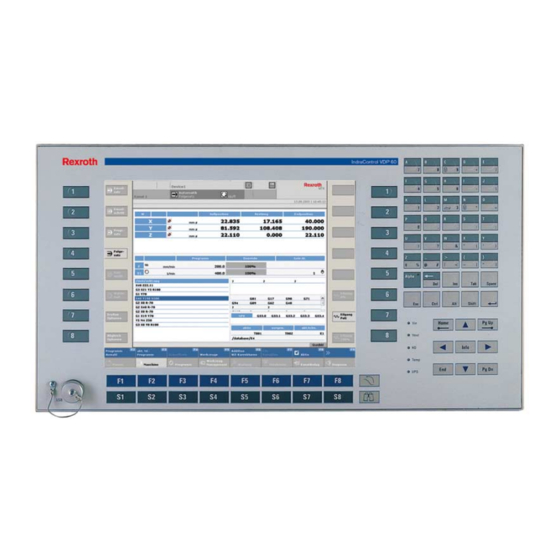
VDP 16.1, VDP 40.1 and VDP 60.1 System Presentation VDP 60.1 VDP 60.1BL with Keypad, 16 Machine Function Keys, Alphanumeric Keys and 12" Display VDP_60.tif Fig. 1-8: VDP 60.1 with keypad Commissioning Mount the device properly (for this, see chapter "Dimensions"). Then, connect the device to the power supply and, if required, to the network. - Page 14 System Presentation VDP 16.1, VDP 40.1 and VDP 60.1 DOK-SUPPL*-VDP16/40/60-PR02-EN-P...
-
Page 15: Important Directions For Use
The user alone carries all responsibility of the risks. Before using Bosch Rexroth products, make sure that all the pre- requisites for appropriate use of the products are satisfied: •... -
Page 16: Areas Of Use And Application
Important Directions for Use VDP 16.1, VDP 40.1 and VDP 60.1 Areas of Use and Application The Displays VDP 16.1, VDP 40.1 and VDP 60.1 of Bosch Rexroth are passive operator visualization terminals, that represent combination with a display VDP 16.1, VDP 40.1 or VDP 60.1 a PC-based machine operator terminal. -
Page 17: Safety Instructions For Electric Drives And Controls
If you do not have the user documentation for your equipment, contact your local Bosch Rexroth representative to send this documentation immediately to the person or persons responsible for the safe operation of this equipment. -
Page 18: Hazards By Improper Use
Safety Instructions for Electric Drives and Controls VDP 16.1, VDP 40.1 and VDP 60.1 Hazards by Improper Use High voltage and high discharge current! Danger to life or severe bodily harm by electric shock! DANGER Dangerous movements! Danger to life, severe bodily harm or material damage by unintentional motor movements! DANGER... -
Page 19: General Information
VDP 16.1, VDP 40.1 and VDP 60.1 Safety Instructions for Electric Drives and Controls General Information • Bosch Rexroth AG is not liable for damages resulting from failure to observe the warnings provided in this documentation. • Read the operating, maintenance and safety instructions in your language before starting up the machine. -
Page 20: Protection Against Contact With Electrical Parts
Safety Instructions for Electric Drives and Controls VDP 16.1, VDP 40.1 and VDP 60.1 • Operation is only permitted if the national EMC regulations for the application are met. The instructions for installation in accordance with EMC requirements can be found in the documentation "EMC in Drive and Control Systems". -
Page 21: Protection Against Electric Shock By Protective Low Voltage (Pelv)
VDP 16.1, VDP 40.1 and VDP 60.1 Safety Instructions for Electric Drives and Controls To be observed with electrical drive and filter components: High electrical voltage on the housing! High leakage current! Danger to life, danger of injury by electric shock! ⇒... -
Page 22: Protection Against Dangerous Movements
Safety Instructions for Electric Drives and Controls VDP 16.1, VDP 40.1 and VDP 60.1 Protection Against Dangerous Movements Dangerous movements can be caused by faulty control of the connected motors. Some common examples are: • improper or wrong wiring of cable connections •... -
Page 23: Protection Against Magnetic And Electromagnetic Fields During Operation And Mounting
VDP 16.1, VDP 40.1 and VDP 60.1 Safety Instructions for Electric Drives and Controls ⇒ Secure vertical axes against falling or dropping after switching off the motor power by, for example: - mechanically securing the vertical axes - adding an external braking/ arrester/ clamping mechanism - ensuring sufficient equilibration of the vertical axes The standard equipment motor brake or an external... -
Page 24: Protection Against Contact With Hot Parts
Safety Instructions for Electric Drives and Controls VDP 16.1, VDP 40.1 and VDP 60.1 Protection Against Contact with Hot Parts Housing surfaces could be extremely hot! Danger of injury! Danger of burns! ⇒ Do not touch housing surfaces near sources of heat! Danger of burns! CAUTION After switching the equipment off, wait at least ten (10) -
Page 25: 3.11 Battery Safety
VDP 16.1, VDP 40.1 and VDP 60.1 Safety Instructions for Electric Drives and Controls 3.11 Battery Safety Batteries contain reactive chemicals in a solid housing. Inappropriate handling may result in injuries or material damage. Risk of injury by incorrect handling! ⇒... - Page 26 3-10 Safety Instructions for Electric Drives and Controls VDP 16.1, VDP 40.1 and VDP 60.1 Notes DOK-SUPPL*-VDP16/40/60-PR02-EN-P...
-
Page 27: Technical Data
Keypad Operation Surface – Front panel Color: RAL 7035 light gray Graphite gray Color: RAL 7035 light gray (Bosch design) Front panel IP 65 according to DIN 40 050, IEC 529 Degree of protection Interface USB connection, No USB connection... -
Page 28: Ambient Conditions
Technical Data VDP 16.1, VDP 40.1 and VDP 60.1 Ambient Conditions Operation Storage/transport Max. ambient temperature +5 °C... +45 °C -20 °C to +60 °C (surrounding air temperature) Max. temperature gradient Temporal temperature changes up to 3 °C Not defined per minute Relative humidity Climatic class 3K3 according to... -
Page 29: Wear Parts
(e.g. lubricants in machine tools) which may interact with our controls and drives, it cannot be completely ruled out that any reactions with the materials used by Bosch Rexroth might occur. For that reason, test new lubricants, cleaning agents, etc. for compatibility with our housings / our housing materials before using the particular material concerned. - Page 30 Technical Data VDP 16.1, VDP 40.1 and VDP 60.1 DOK-SUPPL*-VDP16/40/60-PR02-EN-P...
-
Page 31: Dimensions
VDP 16.1, VDP 40.1 and VDP 60.1 Dimensions Dimensions Dimensions of the VDP Displays Housing Dimensions VDP 16.1 Independent of the design of the VDP 16.1 standard variants with M-Keys or touch screen the front panel width is 350 mm and the height is 290 mm. -
Page 32: Fig. 5-2: Dimesions - Front Panel Vdp 16.1Ac
Dimensions VDP 16.1, VDP 40.1 and VDP 60.1 The front panel width of the VDP 16.1 for the food industry is 360 mm and the height is 300 mm. VDP16.1AC_Frontansicht.FH9 Fig. 5-2: Dimesions – Front panel VDP 16.1AC DOK-SUPPL*-VDP16/40/60-PR02-EN-P... -
Page 33: Fig. 5-3: Vdp 16.1Bb And Vdp 16.1Bk - Bottom View
VDP 16.1, VDP 40.1 and VDP 60.1 Dimensions 167.5 167.5 VDP_16_Ansicht_von_oben.FH9 Fig. 5-3: VDP 16.1BB and VDP 16.1BK – Bottom view VDP_16_Ansicht_von_unten.FH9 Fig. 5-4: VDP 16.1BB and VDP 16.1BK – Bottom view VDP 16.1BB + BK VDP 16.1AC Width 350 mm 360 mm Height 290 mm... -
Page 34: Housing Dimensions Vdp 40.1
Dimensions VDP 16.1, VDP 40.1 and VDP 60.1 Housing Dimensions VDP 40.1 Independent of the design of the VDP 40.1 standard variants with M-Keys or touch screen the front panel width is 407 mm and the height is 370 mm. VDP40.1BE_Frontansicht.FH9 Fig. -
Page 35: Fig. 5-7: Dimensions - Front Panel Vdp 40.1Ag
VDP 16.1, VDP 40.1 and VDP 60.1 Dimensions The front panel width of the VDP 40.1 for the food industry is 417 mm and the height is 380 mm. VDP40.1AG_Frontansicht.FH9 Fig. 5-7: Dimensions – Front panel VDP 40.1AG DOK-SUPPL*-VDP16/40/60-PR02-EN-P... -
Page 36: Fig. 5-8: Vdp 40.1Be And Vdp 40.1Bi - Bottom View
Dimensions VDP 16.1, VDP 40.1 and VDP 60.1 VDP_40_Ansicht_von_oben.FH9 Fig. 5-8: VDP 40.1BE and VDP 40.1BI – Bottom view VDP_40_Ansicht_von_unten.FH9 Fig. 5-9: VDP 40.1BE and VDP 40.1BI – Bottom view VDP 40.1BE + BI VDP 16.1AG Width 407 mm 417 mm Height 370 mm 380 mm... -
Page 37: Housing Dimensions Vdp 60.1
VDP 16.1, VDP 40.1 and VDP 60.1 Dimensions Housing Dimensions VDP 60.1 The front panel width of the display VDP 60.2BL is 483 (19") mm and the height is 266 mm. 482.6 VDP60.1BL_Frontansicht.FH9 Fig. 5-11: Dimensions – Front panel VDP 60.1BL DOK-SUPPL*-VDP16/40/60-PR02-EN-P... -
Page 38: Fig. 5-12: Vdp 60.1Bl - Bottom View
Dimensions VDP 16.1, VDP 40.1 and VDP 60.1 482.6 115.5 18.7 16.1 132.8 132.8 VDP_60_Ansicht_von_oben.FH9 Fig. 5-12: VDP 60.1BL – Bottom view 482.6 VDP_60_Ansicht_von_unten.FH9 Fig. 5-13: VDP 60.1BL – Bottom view VDP 60.1BK Width 483 mm Height 266 mm Installation depth 64.5 mm Fig. -
Page 39: Housing Dimensions Of The Y-Repeater
VDP 16.1, VDP 40.1 and VDP 60.1 Dimensions Housing Dimensions of the Y-Repeater The Y-Repeater is provided for rear panel mounting as well as for mounting on a mounting rail. Support for rear panel mounting 97.6 Mounting rail TS 7.5 x 35 according to DIN EN 50022 66.1... -
Page 40: Installation
5-10 Dimensions VDP 16.1, VDP 40.1 and VDP 60.1 Installation Installation Notes • When installing the display observe to ensure an ergonomic operation. Additionally, ensure that all moving machine components are in sight of the operator. • Avoid installation locations exposed to direct sunlight, as the screen readability is reduced and additional heat development can occur. -
Page 41: Mounting Dimensions Vdp 16.1
5-11 VDP 16.1, VDP 40.1 and VDP 60.1 Dimensions Mounting Dimensions VDP 16.1 167.5 167.5 VDP_16_Montageausschnitt.FH9 Fig. 5-16: Mounting dimensions VDP 16.1 DOK-SUPPL*-VDP16/40/60-PR02-EN-P... -
Page 42: Mounting Dimensions Vdp 40.1
5-12 Dimensions VDP 16.1, VDP 40.1 and VDP 60.1 Mounting Dimensions VDP 40.1 VDP_40_Montageausschnitt.FH9 Fig. 5-17: Mounting dimensions VDP 40.1 DOK-SUPPL*-VDP16/40/60-PR02-EN-P... -
Page 43: Mounting Dimensions Vdp 60.1
5-13 VDP 16.1, VDP 40.1 and VDP 60.1 Dimensions Mounting Dimensions VDP 60.1 465.6 132.8 132.8 454.6 VDP_60_Montageausschnitt.FH9 Fig. 5-18: Mounting dimensions VDP 60.1 DOK-SUPPL*-VDP16/40/60-PR02-EN-P... - Page 44 5-14 Dimensions VDP 16.1, VDP 40.1 and VDP 60.1 DOK-SUPPL*-VDP16/40/60-PR02-EN-P...
-
Page 45: Display And Operating Components
VDP 16.1, VDP 40.1 and VDP 60.1 Display and Operating Components Display and Operating Components Backlight Switch-Off The backlight as background lighting of the display has a limited lifetime (see section "Wear Parts" on page 4-5). To extend the service life of the LCD backlight, the flat screen display features a backlight switch-off. -
Page 46: Fig. 6-2: Windows Xp - Icon "Display
Display and Operating Components VDP 16.1, VDP 40.1 and VDP 60.1 2. Now, click on the "Screen Saver" tab. WindowsXP_Anzeige.bmp Fig. 6-2: Windows XP – Icon "Display" DOK-SUPPL*-VDP16/40/60-PR02-EN-P... -
Page 47: Fig. 6-3: Windows Xp - "Screen Saver" Tab
VDP 16.1, VDP 40.1 and VDP 60.1 Display and Operating Components 3. Now, select the "Power" button. WindowsXP_Bildschirmschoner.bmp Fig. 6-3: Windows XP – "Screen Saver" tab DOK-SUPPL*-VDP16/40/60-PR02-EN-P... -
Page 48: Fig. 6-4: Windows Xp - "Power" Button, Drop-Down List "Turn Off Monitor
Display and Operating Components VDP 16.1, VDP 40.1 and VDP 60.1 4. In the drop-down list under "Settings for Home/Office Desk power scheme" you can specify, in which period of time the backlight switch- off is to be activated. WindowsXP_Monitor_ausschalten.bmp Fig. -
Page 49: Operating And Error Indication
VDP 16.1, VDP 40.1 and VDP 60.1 Display and Operating Components Operating and Error Indication In the upper part of the front panel there are 4 LEDs to indicate the device states and errors. Depending on the variant the front panel provides labeled LEDs or illuminated symbols. -
Page 50: Keypad
Display and Operating Components VDP 16.1, VDP 40.1 and VDP 60.1 Keypad System Requirements To operate the keypad, an English or US keyboard driver is required. Therefore, don't change the corresponding manufacturer's settings. Position of the Keys VDP_16_Lage_der_Tasten.tif Fig. 6-6: Position of the keys VDP 16.1BK and VDP 40.1BI VDP_60_Lage_der_Tasten.tif Fig. -
Page 51: Vdp 16.1 And Vdp 40.1
VDP 16.1, VDP 40.1 and VDP 60.1 Display and Operating Components VDP 16.1 and VDP 40.1 Function and Operation Keys (F... + OP...) The assignment of the function and operation keys is determined by the respective application software / the used operating system. Use of an External Keyboard Concerning the VDP 16.2BK and VDP 40.2BI keypad the key functions can also be activated with an external PC keyboard by pressing the... -
Page 52: Fig. 6-10: Keyboard Telegram
Display and Operating Components VDP 16.1, VDP 40.1 and VDP 60.1 The following key codes are output: Requesting M-Keys via PS/2 Key combinations of the keys Corresponding key of a standard VDP 16.1BK and VDP 40.1BI keyboard M-Keys, left CTRL + ALT + SHIFT LINKS + X ASCII-Block X: 1 ... -
Page 53: Fig. 6-11: Status Byte
VDP 16.1, VDP 40.1 and VDP 60.1 Display and Operating Components In byte 2 a status is transmitted with the following meaning: Value Meaning 0x00 No error 0x01 Directly after Reset, during the self test a M-Key is pressed 0x02 Incoming request telegram before the current keypad telegram is finished Fig. -
Page 54: Vdp 60.1
6-10 Display and Operating Components VDP 16.1, VDP 40.1 and VDP 60.1 VDP 60.1 Function and Special Keys (F... + S...) Key combinations for the keys of Corresponding key of a standard the VDP 60.1BL keyboard Overview (binoculars) SHIFT + SPACE Calling-up the basic screen (stairs) CTRL + HOME Info... -
Page 55: Fig. 6-15: Code 0X10 To 0X1F
6-11 VDP 16.1, VDP 40.1 and VDP 60.1 Display and Operating Components M-Keys Key combinations for the keys of Corresponding key of a standard the VDP 60.1BL keyboard M-Keys, left 1 - 4 F9 - F12 M-Keys, left 5 -8 SHIFT + F9 - SHIFT + F12 M-Keys, right 1 - 4 CTRL + F9 - CTRL + F12... -
Page 56: Touch Screen
6-12 Display and Operating Components VDP 16.1, VDP 40.1 and VDP 60.1 Alphanumeric Block The keys of the alphanumeric block send the default PS/2 codes to the The alpha key is locking "toggeling" and its output is no code, but only controls the keyboard controller. -
Page 57: Light-Emitting Diodes At The Y-Repeater
6-13 VDP 16.1, VDP 40.1 and VDP 60.1 Display and Operating Components Light-Emitting Diodes at the Y-Repeater Three light-emitting diodes are located at the Y-Repeater: Y-Anschluss1.FH9 Fig. 6-17: LED IN0 Y-Repeater_LEDs.FH9 Fig. 6-18: LEDs for VDP1 and VDP2 This three light-emitting diodes have the following meaning: IN0, VDP1 and VDP2 Light-Emitting Diodes Meaning... - Page 58 6-14 Display and Operating Components VDP 16.1, VDP 40.1 and VDP 60.1 DOK-SUPPL*-VDP16/40/60-PR02-EN-P...
-
Page 59: Interfaces
VDP 16.1, VDP 40.1 and VDP 60.1 Interfaces Interfaces Interfaces at the VDP View on the Connector Panel XUSB2 XUSB1 XIPC XPS2KB XPS2MS XDPSLAVE VDP_16_Anschlussfeld.FH9 Fig. 7-1: Position of the interfaces Description of the Interface Interfaces Des. on the Type of connection Type of connector Mating connector or cable housing... -
Page 60: 24 Vdc Power Supply
Interfaces VDP 16.1, VDP 40.1 and VDP 60.1 24 VDC Power Supply X13 – The VDP is provided with the necessary power via the GIGASTAR 24 V Power Supply interface of the IPC. Note: If Y-Repeaters are used, the VDP must be separately provided with a voltage of 24 VDC via connection X13. -
Page 61: Usb Interfaces
VDP 16.1, VDP 40.1 and VDP 60.1 Interfaces USB Interfaces XUSB – Serial Interfaces for The devices feature two USB interfaces on the connector panel (XUSB1 Printer, Scanner, CD-ROM Drive and XUSB2) and one in the front panel (not for devices for the food industry). -
Page 62: Gigastar Interface
Interfaces VDP 16.1, VDP 40.1 and VDP 60.1 GIGASTAR Interface The VDP is connected to the IPC via the 25-pin GIGASTAR interface XIPC – GIGASTAR Interface (XIPC). You will find connecting cables with different length on page 10-4 in chapter "Ordering Information" under "Accessories". Material damage by cable extension! ⇒... -
Page 63: Mouse Interface
VDP 16.1, VDP 40.1 and VDP 60.1 Interfaces Mouse Interface The mouse interface (XPS2MS) can be connected to an external mouse. The data are transmitted via the GIGASTAR interface to the IPC. XPS2MS – PS/2 Mouse Interface PS/2 Mini-DIN female connector, 6-pin Cable length: Max. -
Page 64: Profibus Dp Interface
Interfaces VDP 16.1, VDP 40.1 and VDP 60.1 PROFIBUS DP Interface Optionally, the connection XDPSLAVE provides a PROFIBUS DP SLAVE XDPSLAVE – PROFIBUS DP interface according to DIN EN 50170, Part 2. This interface allows to Interface request the states of the M-Keys available for devices with keypad (see section M-Keys in chapter 6 on page 6-6 and 6-10). -
Page 65: Interfaces At The Y-Repeater
VDP 16.1, VDP 40.1 and VDP 60.1 Interfaces Interfaces at the Y-Repeater View on the Connector Panels The connections are located at the two shorter sides of the Y-Repeater: Y-Anschluss1.FH9 Fig. 7-11: Interface to the IPC Y-Anschluss2.FH9 Fig. 7-12: Interface to the VDP displays Description of the Interface Overview Des. -
Page 66: Gigastar Interface
Interfaces VDP 16.1, VDP 40.1 and VDP 60.1 GIGASTAR Interface Via the 25-pin GIGASTAR interface (X31, X32, X33) the Y-Repeater is X31, X32, X33 – connected, on the one hand, to the IPC and, on the other hand, to the two GIGASTAR Interfaces VDP displays. -
Page 67: Digital 24 V Input (Changeover Input)
VDP 16.1, VDP 40.1 and VDP 60.1 Interfaces Digital 24 V Input (Changeover Input) X21 – The selection, which of the VDP displays connected to the Y-Repeater is Digital 24 V Input activated, occurs via a digital 24 V input. As the image signals are transmitted to both VDP displays, data can only be entered with the active VDP. - Page 68 7-10 Interfaces VDP 16.1, VDP 40.1 and VDP 60.1 DOK-SUPPL*-VDP16/40/60-PR02-EN-P...
-
Page 69: Maintenance And Installation
A fading backlight causes a progressive deterioration of the LCD display's readability, so that a backlight exchange is necessary. For further information please contact the Bosch Rexroth Service. Connection of Two VDP Displays via the Y-Repeater To connect two VDP displays to one IPC, the Y-Repeater is available as accessories. - Page 70 Maintenance and Installation VDP 16.1, VDP 40.1 and VDP 60.1 Note: The end devices (mouse, keyboard) connected to the two VDP displays must be of the same type (e.g. a two-key mouse). Otherwise, it is not possible to switch between the two VDP displays.
-
Page 71: Touch Screen Software
VDP 16.1, VDP 40.1 and VDP 60.1 Touch Screen Software Touch Screen Software In the displays VDP 16.1BB, VDP 16.1AC as well as VDP 40.1BE and VDP 40.1AG a touch screen is used, that allows the operation via the touch-sensitive surface of the displays. The touch screen controller communicates with the PC via the GIGASTAR interface using the serial interface COM2 of the IPC. - Page 72 Touch Screen Software VDP 16.1, VDP 40.1 and VDP 60.1 DOK-SUPPL*-VDP16/40/60-PR02-EN-P...
-
Page 73: Ordering Information
10-1 VDP 16.1, VDP 40.1 and VDP 60.1 Ordering Information Ordering Information 10.1 Type Code According to the following type codes there are different variants of the displays VDP 16.1, VDP 40.1 and VDP 60.1. VDP 16.1 Abbrev. Column 1 2 3 4 6 7 8 9 1 2 3 4 6 7 8 9... -
Page 74: Vdp 40.1
10-2 Ordering Information VDP 16.1, VDP 40.1 and VDP 60.1 VDP 40.1 Abbrev. Column 1 2 3 4 6 7 8 9 1 2 3 4 6 7 8 9 1 2 3 4 6 7 8 9 1 2 3 4 6 7 8 9 Example: V D P 4 0 . -
Page 75: Vdp 60.1
10-3 VDP 16.1, VDP 40.1 and VDP 60.1 Ordering Information VDP 60.1 Abbrev. Column 1 2 3 4 6 7 8 9 1 2 3 4 6 7 8 9 1 2 3 4 6 7 8 9 1 2 3 4 6 7 8 9 Example: V D P 6 0 . -
Page 76: 10.2 Accessories
10-4 Ordering Information VDP 16.1, VDP 40.1 and VDP 60.1 10.2 Accessories Y-Repeater To connect two VDP displays to one IPC, the Y-Repeater is provided. Ordering designation Part number Description VAC01.1S-YG4-NNNN R911307623 Y-Repeater for GIGASTAR Fig. 10-4: Y-Repeater Connecting Cable to the IPC 40.2 (GIGASTAR Interfaces) Using a Y-Repeaters the following cables are utilized also to connect IPC and Y-Repeater as well as to connect Y-Repeater and VDP. -
Page 77: List Of Figures
11-1 VDP 16.1, VDP 40.1 and VDP 60.1 List of Figures List of Figures Fig. 1-1: Distinguishing features VDP 16.1 1-1 Fig. 1-2: Distinguishing features VDP 40.1 1-1 Fig. 1-3: Features VDP 60.1 1-2 Fig. 1-4: VDP 16.1 with touch screen 1-3 Fig. - Page 78 11-2 List of Figures VDP 16.1, VDP 40.1 and VDP 60.1 Fig. 6-8: Key combinations of the keys VDP 16.1BK and VDP 40.1BI 6-7 Fig. 6-9: Key combinations of the keys VDP 16.1BK and VDP 40.1BI 6-8 Fig. 6-10: Keyboard telegram 6-8 Fig.
-
Page 79: Index
12-1 VDP 16.1, VDP 40.1 and VDP 60.1 Index Index Accessories 10-4 Addressing of the M-Keys 6-7 Air pressure 4-2 Ambient Conditions 4-2 Appropriate use Introduction 2-1 Uses 2-2 Backlight switch-off 6-1 CE marking 4-2 Changeover input 7-9 Combined keyboard/mouse interface 7-4 Compatibility test 4-3 Connecting cable to the Y-Repeater 10-4 Digital 24 V input 7-9... - Page 80 12-2 Index VDP 16.1, VDP 40.1 and VDP 60.1 Inappropriate use 2-2 Consequences, Discharge of liability 2-1 Interface at the VDP GIGASTAR 7-4 Interfaces 7-1 Interfaces at the VDP 7-1 PROFIBUS DP 7-6 PS/2 7-4 USB 7-3 Interfaces at the Y-Repeater 7-7 Changeover input 7-9 Digital input 7-9 GIGASTAR 7-8...
- Page 81 12-3 VDP 16.1, VDP 40.1 and VDP 60.1 Index Relative humidity 4-2 Rotary switch 7-1 Safety Instructions for Electric Drives and Controls 3-1 Software Touch Screen 9-1 Standards 4-2 Storage media 10-4 System presentation 1-1 Brief description 1-1 Commissioning 1-7 Variants 1-1 Technical data Wear parts 4-3...
- Page 82 12-4 Index VDP 16.1, VDP 40.1 and VDP 60.1 DOK-SUPPL*-VDP16/40/60-PR02-EN-P...
-
Page 83: Service & Support
13-1 VDP 16.1, VDP 40.1 and VDP 60.1 Service & Support Service & Support 13.1 Helpdesk Unser Kundendienst-Helpdesk im Hauptwerk Lohr Our service helpdesk at our headquarters in Lohr am am Main steht Ihnen mit Rat und Tat zur Seite. Main, Germany can assist you in all kinds of inquiries. -
Page 84: 13.5 Kundenbetreuungsstellen
Tel.: +49 (0)171 333 88 26 service.svc@boschrexroth.de Vertriebsgebiet Süd Vertriebsgebiet West Gebiet Südwest Germany South Germany West Germany South-West Bosch Rexroth AG Bosch Rexroth AG Bosch Rexroth AG Landshuter Allee 8-10 Regionalzentrum West Service-Regionalzentrum Süd-West 80637 München Borsigstrasse 15 Siemensstr. 1... - Page 85 - Italien Netherlands - Niederlande/Holland Netherlands – Niederlande/Holland Bosch Rexroth S.p.A. Bosch Rexroth S.p.A. Bosch Rexroth Services B.V. Bosch Rexroth B.V. Via del Progresso, 16 (Zona Ind.) Via Isonzo, 61 Technical Services Kruisbroeksestraat 1 35020 Padova 40033 Casalecchio di Reno (Bo) Kruisbroeksestraat 1 (P.O.
- Page 86 - Tschechien Czech Republic - Tschechien Hungary - Ungarn Poland – Polen DEL a.s. Bosch -Rexroth, spol.s.r.o. Bosch Rexroth Kft. Bosch Rexroth Sp.zo.o. Strojírenská 38 Hviezdoslavova 5 Angol utca 34 ul. Staszica 1 591 01 Zdar nad Sázavou 627 00 Brno 1149 Budapest 05-800 Pruszków...
- Page 87 Australia - Australien Australia - Australien China China AIMS - Australian Industrial Bosch Rexroth Pty. Ltd. Shanghai Bosch Rexroth Shanghai Bosch Rexroth Machinery Services Pty. Ltd. No. 7, Endeavour Way Hydraulics & Automation Ltd. Hydraulics & Automation Ltd. 28 Westside Drive...
- Page 88 Canada West - Kanada West Mexico Mexico Bosch Rexroth Canada Corporation Bosch Rexroth Canada Corporation Bosch Rexroth Mexico S.A. de C.V. Bosch Rexroth S.A. de C.V. Burlington Division 5345 Goring St. Calle Neptuno 72 Calle Argentina No 3913 3426 Mainway Drive Burnaby, British Columbia Unidad Ind.
- Page 90 Bosch Rexroth AG Electric Drives and Controls P.O. Box 13 57 97803 Lohr, Germany Bgm.-Dr.-Nebel-Str. 2 97816 Lohr, Germany Phone +49 (0)93 52-40-50 60 +49 (0)93 52-40-49 41 service.svc@boschrexroth.de www.boschrexroth.com Printed in Germany R911307654 DOK-SUPPL*-VDP16/40/60-PR02-EN-P...
Need help?
Do you have a question about the Rexroth IndraControl VDP 16.1 Series and is the answer not in the manual?
Questions and answers