Sign In
Upload
Manuals
Brands
Bosch Manuals
Monitor
Rexroth IndraControl VDP 40.1
Bosch Rexroth IndraControl VDP 40.1 Manuals
Manuals and User Guides for Bosch Rexroth IndraControl VDP 40.1. We have
2
Bosch Rexroth IndraControl VDP 40.1 manuals available for free PDF download: Project Planning Manual
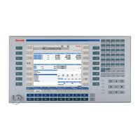
Bosch Rexroth IndraControl VDP 40.1 Project Planning Manual (90 pages)
Brand:
Bosch
| Category:
Touch terminals
| Size: 2.74 MB
Table of Contents
Table of Contents
3
System Presentation
7
Brief Description VDP 16.1, VDP 40.1 and VDP 60.1
7
Variants
7
Distinguishing Features
7
Displays with Keypad
8
Displays with Touch Screen
8
Variants VDP 16.1
9
Fig. 1-4: VDP 16.1 with Touch Screen
9
Fig. 1-5: VDP 16.1 with Keypad
10
Variants VDP 40.1
11
Fig. 1-6: VDP 40.1 with Touch Screen
11
Fig. 1-7: VDP 40.1 with Keypad
12
Vdp 60.1
13
Commissioning
13
Fig. 1-8: VDP 60.1 with Keypad
13
Important Directions for Use
15
Appropriate Use
15
Introduction
15
Areas of Use and Application
16
Inappropriate Use
16
Safety Instructions for Electric Drives and Controls
17
Introduction
17
Explanations
17
Fig. 3-1: Hazard Classification (According to ANSI Z535)
17
Hazards by Improper Use
18
General Information
19
Protection against Contact with Electrical Parts
20
Protection against Electric Shock by Protective Low Voltage (PELV)
21
Protection against Dangerous Movements
22
Protection against Magnetic and Electromagnetic Fields During Operation and Mounting
23
Protection against Contact with Hot Parts
24
3.10 Protection During Handling and Mounting
24
3.11 Battery Safety
25
3.12 Protection against Pressurized Systems
25
Technical Data
27
Front Panel
27
Power Supply
27
Ambient Conditions
28
Used Standards
28
Wear Parts
29
Compatibility Test
29
Fig. 4-6: Service Life of the Backlight
29
Fig. 4-7: Service Life of the Fan
29
Dimensions
31
Dimensions of the VDP Displays
31
Housing Dimensions VDP 16.1
31
Fig. 5-1: Dimensions - Front Panel VDP 16.1BK
31
Fig. 5-2: Dimesions - Front Panel VDP 16.1AC
32
Fig. 5-3: VDP 16.1BB and VDP 16.1BK - Bottom View
33
Fig. 5-4: VDP 16.1BB and VDP 16.1BK - Bottom View
33
Housing Dimensions VDP 40.1
34
Fig. 5-6: Dimensions - Front Panel VDP 40.1BE and VDP 40.1BI
34
Fig. 5-7: Dimensions - Front Panel VDP 40.1AG
35
Fig. 5-8: VDP 40.1BE and VDP 40.1BI - Bottom View
36
Fig. 5-9: VDP 40.1BE and VDP 40.1BI - Bottom View
36
Housing Dimensions VDP 60.1
37
Fig. 5-11: Dimensions - Front Panel VDP 60.1BL
37
Fig. 5-12: VDP 60.1BL - Bottom View
38
Fig. 5-13: VDP 60.1BL - Bottom View
38
Housing Dimensions of the Y-Repeater
39
Fig. 5-15: Dimensions of the Y-Repeater
39
Installation
40
Installation Notes
40
Mounting Cut-Out
40
Mounting Dimensions VDP 16.1
41
Mounting Dimensions VDP 40.1
42
Mounting Dimensions VDP 60.1
43
Display and Operating Components
45
Backlight Switch-Off
45
Fig. 6-1: Windows XP - Control Panel
45
Fig. 6-2: Windows XP - Icon "Display
46
Fig. 6-3: Windows XP - "Screen Saver" Tab
47
Fig. 6-4: Windows XP - "Power" Button, Drop-Down List "Turn off Monitor
48
Operating and Error Indication
49
Fig. 6-5: Leds to Indicate Operations and Errors on the Front Panel
49
Keypad
50
System Requirements
50
Position of the Keys
50
VDP 16.1 and VDP 40.1
51
Fig. 6-8: Key Combinations of the Keys VDP 16.1BK and VDP 40.1BI
51
Fig. 6-9: Key Combinations of the Keys VDP 16.1BK and VDP 40.1BI
51
Fig. 6-10: Keyboard Telegram
52
Fig. 6-11: Status Byte
53
Fig. 6-12: Assignment of the M-Keys at the PROFIBUS DP
53
Vdp 60.1
54
Fig. 6-13: Key Combinations for the Keys of the VDP 60.1BL
54
Fig. 6-14: Key Combinations for the Keys of the VDP 60.1BL
54
Fig. 6-15: Code 0X10 to 0X1F
55
Fig. 6-16: Code 0X20 to 0X2F
55
Touch Screen
56
Light-Emitting Diodes at the Y-Repeater
57
Fig. 6-17: LED IN0
57
Fig. 6-18: Leds for VDP1 and VDP2
57
Fig. 6-19: Meaning of the Leds on the Y-Repeater
57
Interfaces
59
Interfaces at the VDP
59
View on the Connector Panel
59
Description of the Interface
59
Fig. 7-1: Position of the Interfaces
59
Fig. 7-3: Rotary Switch
59
24 VDC Power Supply
60
Fig. 7-4: 24 VDC Power Supply X13
60
USB Interfaces
61
Fig. 7-5: USB Interfaces XUSB1 and XUSB2
61
GIGASTAR Interface
62
Combined Keyboard/Mouse Interface
62
Fig. 7-6: Combined Keyboard/Mouse Interface XPS2KB
62
Mouse Interface
63
Fig. 7-7: Mouse Interface XPS2MS
63
PROFIBUS DP Interface
64
Fig. 7-8: PROFIBUS DP Interface
64
Fig. 7-9: Parameters for PROFIBUS DP Line
64
Fig. 7-10: Maximum Segment Length in Relation to the Transmission Rate
64
Interfaces at the Y-Repeater
65
View on the Connector Panels
65
Description of the Interface
65
Connection of the Y-Repeater (Block Diagram)
65
GIGASTAR Interface
66
Fig. 7-15: Assignment of the Three GIGASTAR Interfaces
66
Fig. 7-16: Permissible Cable Length of the GIGASTAR Interfaces
66
Digital 24 V Input (Changeover Input)
67
Fig. 7-17: Assignment of the Digital 24 V Input
67
Fig. 7-18: Pin Assignment X21
67
Fig. 7-19: Selection of the Active VDP
67
Fig. 7-20: Characteristic Value of the Digital 24 V Input
67
Maintenance and Installation
69
General Information
69
LCD Display
69
Connection of Two VDP Displays Via the Y-Repeater
69
Touch Screen Software
71
Ordering Information
73
10.1 Type Code
73
Vdp 16.1
73
Vdp 40.1
74
Vdp 60.1
75
10.2 Accessories
76
Y-Repeater
76
Connecting Cable to the IPC 40.2 (GIGASTAR Interfaces)
76
Storage Media
76
List of Figures
77
Index
79
Service & Support
83
13.1 Helpdesk
83
13.2 Service-Hotline
83
13.3 Internet
83
Vor der Kontaktaufnahme
83
13.5 Kundenbetreuungsstellen
84
Sales & Service Facilities
84
Advertisement
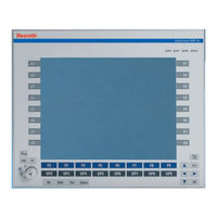
Bosch Rexroth IndraControl VDP 40.1 Project Planning Manual (72 pages)
Operator Display
Brand:
Bosch
| Category:
Monitor
| Size: 4.58 MB
Table of Contents
Table of Contents
3
1 System Presentation
7
Brief Description of the VDP 16.1, VDP 40.1 and VDP 60.1 Operator Displays
7
Variants
7
Characteristic Features
7
Displays with Foil Keyboard
8
Displays with Touch Screen
8
VDP 16.1 Variants
8
VDP 40.1 - Variants
9
Vdp 60.1
10
Accessories
11
Commissioning
11
2 Important Instructions on Use
13
Appropriate Use
13
Introduction
13
Areas of Use and Application
13
Inappropriate Use
14
3 Safety Instructions for Electric Drives and Controls
15
Definitions of Terms
15
General Information
16
Using the Safety Instructions and Passing Them on to Others
16
Requirements for Safe Use
16
Hazards by Improper Use
17
Instructions with Regard to Specific Dangers
18
Protection against Contact with Electrical Parts and Housings
18
Protective Extra-Low Voltage as Protection against Electric Shock
19
Protection against Dangerous Movements
19
Protection against Magnetic and Electromagnetic Fields During Operation and Mounting
21
Protection against Contact with Hot Parts
21
Protection During Handling and Mounting
21
Battery Safety
22
Protection against Pressurized Systems
22
Explanation of Signal Words and the Safety Alert Symbol
23
4 Technical Data
25
Front Panel
25
Voltage Supply
25
Ambient Conditions
26
Standards
26
Used Standards
26
CE Marking
27
Declaration of Conformity
27
Note for the Machine Manufacturer
27
UL/CSA Certified
27
Wear Parts
28
Compatibility Test
28
5 Dimensions and Installation
29
Housing Dimensions
29
Housing Dimensions VDP 16.1
29
Housing Dimensions VDP 40.1
31
Housing Dimensions VDP 60.1
33
Housing Dimensions of the Y-Repeater
33
Installation
34
Installation Notes
34
Mounting Cut-Out
34
Mounting Dimensions VDP 16.1
36
Mounting Dimensions VDP 40.1
37
Mounting Dimensions VDP 60.1
37
6 Display and Operating Components
39
Backlight Switch-Off
39
General Information
39
Operating and Error Displays
39
Foil Keyboard
40
System Requirements
40
Position of the Buttons
41
VDP 16.1 Keys and VDP 40.1 Keys
41
Function and Operating Keys (F
41
Use of an External Keypad
41
M-Keys
42
Keys VDP 60.1
43
Function and Special Keys (F
43
M-Keys
44
Alphanumeric Block
45
Touch Screen
45
Leds at the Y-Repeater
45
7 Interfaces
47
Interfaces at the VDP
47
View on the Connector Panel
47
General Information
47
Overview
47
S3/S4 Rotary Switch
48
Overview
48
DC 24 V Voltage Supply
48
XUSB Interfaces
49
G4 Display Interface
50
Combined Keyboard/Mouse Interface
50
Mouse Interface
50
PROFIBUS DP Interface
51
Intefaces at the Y-Repeater
52
View on the Connector Panels
52
Description of the Interfaces - Overview
53
Connection of the Y-Repeater (Block Diagram)
53
G4 Display Interfaces
53
Digital 24 V Input (Changeover Input)
54
8 Maintenance
57
General Information
57
LCD Display
57
Connecting Two Vdps Via the Y-Repeater
58
9 Software
59
Touch Screen Software
59
10 Environmental Protection and Disposal
61
Environmental Protection
61
Disposal
61
11 Ordering Information
63
Type Designation Code
63
General Information
63
Vdp 16.1
63
Vdp 40.1
63
Vdp 60.1
64
Accessories
66
Y-Repeater
66
Connecting Cable to Control Cabinet PC IPC 40.2
66
12 Service and Support
67
Index
69
Advertisement
Related Products
Bosch Rexroth IndraControl VDP 40.3
Bosch Rexroth IndraControl VDP 40.3 DE
Bosch Rexroth IndraControl VDP 40.3 BI
Bosch Rexroth IndraControl VDP 40.3 DF
Bosch Rexroth IndraControl VDP 40.3 DG
Bosch Rexroth IndraControl VDP 40.3 DI
Bosch Rexroth IndraControl VDP 40.3 AL
Bosch Rexroth IndraControl VDP 21.3
Bosch Rexroth IndraControl VDP 60.1
Bosch Rexroth IndraControl VDP 60.3
Bosch Categories
Dishwasher
Washer
Oven
Power Tool
Dryer
More Bosch Manuals
Login
Sign In
OR
Sign in with Facebook
Sign in with Google
Upload manual
Upload from disk
Upload from URL