Advertisement
Quick Links
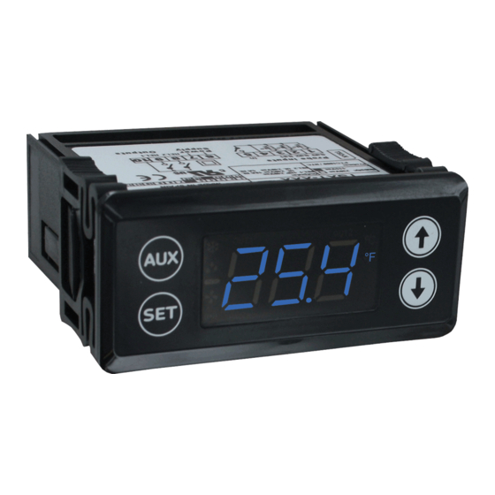
Series TSXT Digital Temperature Switch
Specifications - Installation and Operating Instructions
The Series TSXT Digital Temperature Switch is designed with many refrigeration
applications in mind. It accepts up to 3 temperature inputs, of either PTC or NTC
temperature probe types and can control the compressor, defrost, fan, alarm, and
light in a refrigeration system. These switches allow master/slave configuration to
synchronize the defrost cycle between different units. The Series TSXT programming
performed by the front keypad, the TS2-K programming key, or by RS485 module
communication. Standard features include capacitive buttons, real time clock, HACCP
alarm logging, temperature alarms, and password protected parameter settings.
MODEL CHART
Model
Supply Power Outputs Model
TSXT-211
115 VAC
1
TSXT-221
230 VAC
1
TSXT-231
12 VAC/VDC
1
TSXT-241
24 VAC/VDC
1
TSXT-212
115 VAC
2
TSXT-222
230 VAC
2
INSTALLATION
Note: Unit must be mounted away from vibration, impacts, water, and corrosive gases.
• Cut hole in panel 2.80 x 1.14 inches (71 x 29 mm).
• Use the included gasket, or apply silicone around the perimeter of the hole to prevent
leakage.
• Insert the unit into the hole in panel.
• Slide removable fitting clips onto unit from back until secure to panel.
• Wire the unit per the wiring diagram on the product label or by figures below. Avoid
installing temperature probe and digital input wiring in the proximity of power cables.
Wiring Diagram
Sd3 Sd2 Sd1 Com In
1
2
3
4
5
1 relay output
Sd3 Sd2 Sd1 Com In
1
2
3
4
5
2 relay outputs
DWYER INSTRUMENTS, INC.
P.O. BOX 373 • MICHIGAN CITY, INDIANA 46360, U.S.A.
Supply Power Outputs
TSXT-232
12 VAC/VDC
2
TSXT-242
24 VAC/VDC
2
TSXT-213
115 VAC
3
TSXT-223
230 VAC
3
TSXT-233
12 VAC/VDC
3
TSXT-243
24 VAC/VDC
3
6
7
8
9
10
REL1
COM
POWER
SUPPLY
TSXT-XX1
6
7
8
9
10
REL2 REL1 COM
POWER
SUPPLY
TSXT-XX2
3.110 [79.0]
AUX
SET
Panel cutout 2-51/64˝ x 1-9/64˝ (71 x 29 mm)
SPECIFICATIONS
Probe Range: PTC: -58 to 302°F (-50 to 150°C); NTC: -58 to 230°F (-50 to 110°C).
Input: PTC (1000 Ω @ 25°C) or NTC (10 KΩ @ 25°C) thermistor.
Output: Relay 1: SPST relay rated 16 A @ 240 VAC resistive, 10 FLA, 60 LRA;
Relay 2: SPST relay rated 5 A @ 240 VAC resistive; Relay 3: SPST relay rated 8 A
@ 240 VAC resistive.
Horsepower Rating (HP): 1 HP (Relay 1).
Control Type: On/off with defrost options.
Power Requirements: 115 VAC, 230 VAC, 24 VAC/VDC, or 12 VAC/VDC.
Power Consumption: 3.6 VA @ 115/230 VAC; 1.5 VA @ 12/24 VAC/VDC.
Accuracy: ±1% FS.
Display: 3-digit, plus sign.
Resolution: 0.1°.
Memory Backup: Nonvolatile memory.
Ambient Operating Temperature: 32 to 131°F (0 to 55°C).
Storage Temperature: -4 to 176°F (-20 to 80°C).
Weight: 115 and 230 V models: 7.2 oz (204 g); 12 and 24 V models: 4.8 oz (136 g).
Front Panel Rating: IP65.
Agency Approvals: CE, cURus.
Sd3 Sd2 Sd1 Com In
1
2
3
4
5
TSXT-XX3
3 relay outputs
Phone: 219/879-8000
Fax: 219/872-9057
Bulletin T-TSXT
GASKET
2.440 [62.0]
1.440
[36.5]
6
7
8
9
10
REL2 REL1 COM REL3
POWER
SUPPLY
www.dwyer-inst.com
e-mail: info@dwyermail.com
1.110
[28.3]
11
Advertisement

Related Manuals for Dwyer Instruments TSXT Series


Summary of Contents for Dwyer Instruments TSXT Series
- Page 1 TSXT-XX3 1 relay output 3 relay outputs Sd3 Sd2 Sd1 Com In REL2 REL1 COM POWER SUPPLY TSXT-XX2 2 relay outputs DWYER INSTRUMENTS, INC. Phone: 219/879-8000 www.dwyer-inst.com P.O. BOX 373 • MICHIGAN CITY, INDIANA 46360, U.S.A. Fax: 219/872-9057 e-mail: info@dwyermail.com...
- Page 2 Parameter Programming Activating and Deactivating Manual Defrost Cycle Note: Set Point and the time programming are the only parameters accessible without Press and hold the AUX button for 2 seconds to activate defrosting. Repeat this access code. process to stop the defrosting. If a cool cycle is activated, the defrosting is disabled. Set Point Activating and Deactivating Cool Cycle •...
- Page 3 List of Parameters Parameter Descriptions Compressor (COn) COn Description Units Range SET = Working Set Point. Temperature the system trys to maintain. Variable Set point Degrees r1 to r2 between r1 and r2. Differential or hysteresis Degrees 0.1 to 20 r0 = Differential.
- Page 4 Be sure to include a brief description of the problem plus any additional application notes. ©Copyright 2020 Dwyer Instruments, Inc. Printed in U.S.A. 5/20 FR# 444246-00 Rev. 1 DWYER INSTRUMENTS, INC.
Need help?
Do you have a question about the TSXT Series and is the answer not in the manual?
Questions and answers