Advertisement
Quick Links
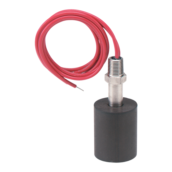
(Model F7-SB Shown)
Dimensions, Inches (mm)
(A) Stem
(B) Float
(C) Float
Model
Length
Diameter
Height
F7-SB
2.75 (70)
1.13 (29)
1.38 (35)
F7-SS2
2.06 (52)
1.0 (25)
1.0 (25)
F7-PP
2.18 (55)
1.18 (30)
1.0 (25)
F7-BT
2.18 (55)
1.18 (30)
1.0 (25)
F7-MPP
1.63 (41)
0.63 (16)
0.63 (16)
SWITCH ACTION (Normally open/Normally closed)
Vertical Models
Vertical mount models are shipped with normally open switch contacts which close
as the float rises toward the mounting threads. Reverse switch action by removing
the float, rotating it end-for-end and replacing it on the stem.
Horizontal Models
Contacts in horizontal models F7-HPS-1 (internal mount) and F7-HPS-2 (external
mount), are normally open when the float is down and normally closed when the
float is up. Models F7-HPS-1 and -2 also have indicating arrows on the stem end
to confirm float alignment. See installation notes on reverse. Horizontal model F7-
HSS is in the normally open position when the indicating arrow points up, and
normally closed when the arrow points down.
INSTALLATION
Choose a location away from fill pipes, drains, or other areas where turbulence or
wave motion might occur. Turbulence will cause false actuations and shorten
contact life. Excess contaminants in fluid may inhibit float operation and occasional
wipe-down may be necessary. Care should be taken that switches are always
operated within electrical ratings. Read and understand all safety precautions on
back of this sheet before installing.
MOUNTING
Install vertical mount models in an appropriate 1/8˝ NPT fitting. Vertical models
mount internally, oriented within 30° of vertical, or select optional fittings for
external mounting. Model F7-HPS-1 must be mounted internally, which means the
switch must be secured to the wall of the tank or vessel from the inside. Install
horizontal model F7-HPS-1 in a 5/8˝ (16 mm) hole and secure with nut provided.
Tank wall should not exceed 1/8˝ (3 mm). Model F7-HPS-2 requires a horizontal
1/2˝ NPT(F) fitting and can be fitted to the tank or vessel from the outside. Model
F7-HSS requires a horizontal 1/2˝ NPT(F) fitting and can be mounting from the
inside or outside (internally or externally) of the tank or vessel.
DWYER INSTRUMENTS, INC.
P.O. BOX 373 • MICHIGAN CITY, INDIANA 46360, U.S.A.
Series F7 Liquid Level Switches
Specifications - Installation and Operating Instructions
PIPE
ELBOW
COUPLING
13/16 [20.62]
MAX
(D) Actuation
from HEX
1-19/32
1.0 (26)
[40.46]
0.73 (19)
0.69 (18)
F7-HPS-2, EXTERNAL HORIZONTAL MOUNT
0.69 (18)
0.47 (12)
QualityInstruments-Direct
EXTERNALLY
WELDED FLANGE
FITTING
CENTERLINE
PIPE
D A
C
APPROXIMATE
ACTUATION LEVEL
B
SWITCH CLOSED POSITION
3-7/16 [87.29]
2-23/64 [59.92]
3/4
2 [50.80]
[19.05]
40∞ MAX
1/2 NPT
SWITCH OPEN
POSITION
SPECIFICATIONS
Electrical Rating (Maximum):
F7-SB, SS2:
F7-PP, BT, HSS: AC: 30 VA, 0.14A @ 200V.
F7-MPP:
F7-MPP-NO:
F7-HPS:
Mounting Connections: 1/8˝ NPT(M) (all vertical mount), 1/2˝ NPT(M) (F7-HPS-
2, F7-HSS), M16 x 2 (F7-HPS-1).
Wire Leads: F7-SB, SS2, PP, BT: 22 AWG x 18˝ (46 cm); F7-MPP, HSS: 22
AWG x 24˝ (61 cm); F7-HPS: 22 AWG x 39˝ (1m).
Enclosure Rating: F7-HSS: Explosion-proof, Class 1, Groups A, B, C, D; Class
II, Groups E, F, G; Class III.
Weight: F7-SB, 2 oz. (58 g); F7-SS2, 1.2 oz. (34 g); F7-PP, 0.8 oz. (23 g); F7-
BT, 0.7 oz. (20 g); F7-HPS-1, 1.5 oz. (43 g); F7-HPS-2, 2 oz. (57 g); F7-HSS, 3
oz. (94 g); F7-MPP, 0.8 oz. (23 g).
Material
Model
Float/Stem
Vertical Mount
F7-SB
Buna-N & Epoxy/316SS
F7-SS2
316SS (CYC)/316SS
F7-PP
Polypropylene &
Epoxy/Polypropylene
F7-BT
Buna-N & Epoxy/PBT*
F7-MPP
Polypropylene /
Polypropylene
Horizontal Mount
F7-HPS
Polysulfone/
-1, -2
Polysulfone
F7-HSS
316SS/316SS
*PBT - Polybutylene Terephthalate
Optional Fittings (for Exterior Mounting of Vertical Models)
A-347, 1/8˝ x 1-1/4˝ NPT C.S. Adapter.
A-347-SS, 1/8˝ x 1-1/4˝ NPT 316SS Adapter.
A-348, 1/8˝ x 1-1/2˝ NPT C.S. Adapter.
A-348-SS, 1/8˝ x 1-1/2˝ NPT 316SS Adapter.
Phone: 219/879-8000
Fax: 219/872-9057
13/16 MIN
[20.6]
3/32
1-7/32 MAX
[2.54]
[31.0]
1-5/32 MAX
[29.2]
4-5/8 MAX
[116.8]
F7-HSS
13/16 [20.62]
2-15/64 [56.74]
DIA. MAX.
SWITCH CLOSED
POSITION
40∞ MAX
1-33/64
[38.48]
F7-HPS-2, INTERNAL HORIZONTAL MOUNT
AC: 25 VA, 1A @ 200 V.
DC: 10W, 1A @ 200V.
DC: 0.28A @ 24 V, 0.07A @ 120V.
10 VA, 0.1A @ 120 VAC.
50 VA, 0.2A @ 240 VAC.
15 VA, 1A @ 220 VAC/DC.
Max
Max
Min
Temp.
Press.
S.G.
220°F
150 psig
0.60
105°C
10 bar
300°F
450 psig
0.75
149°C
31 bar
220°F
100 psig
0.60
105°C
6.89 bar
220°F
150 psig
0.45
105°C
10 bar
176° F
100 psig
0.90
80° C
6.89 bar
185°F
150 psig
0.85
85°C
10 bar
392°F
300 psig
0.60
200°C
20.7 bar
www.dwyer-inst.com
e-mail: info@dwyermail.com
1.800.868.7495
.ca
Bulletin E-75
22 AWG
LEAD WIRES
1/2-14 NPT
3-15/32 [88/09]
M16X2
SWITCH OPEN
POSITION
Approx.
Deadband
1/16˝
2 mm
1/16˝
2 mm
1/8˝
4 mm
1/8˝
4 mm
1/8˝
4 mm
3/16˝
5 mm
1/8˝
4 mm
Advertisement

Related Manuals for Dwyer Instruments F7 Series


Summary of Contents for Dwyer Instruments F7 Series
- Page 1 A-347, 1/8˝ x 1-1/4˝ NPT C.S. Adapter. A-347-SS, 1/8˝ x 1-1/4˝ NPT 316SS Adapter. A-348, 1/8˝ x 1-1/2˝ NPT C.S. Adapter. A-348-SS, 1/8˝ x 1-1/2˝ NPT 316SS Adapter. DWYER INSTRUMENTS, INC. Phone: 219/879-8000 www.dwyer-inst.com P.O. BOX 373 • MICHIGAN CITY, INDIANA 46360, U.S.A.
- Page 2 V-0.12 R 5R > R REED REED SWITCH SWITCH SWITCH SWITCH ©Copyright 2014 Dwyer Instruments, Inc. Printed in U.S.A. 7/14 FR# 82-440677-00 Rev. 5 DWYER INSTRUMENTS, INC. Phone: 219/879-8000 www.dwyer-inst.com P.O. BOX 373 • MICHIGAN CITY, INDIANA 46360, U.S.A. QualityInstruments-Direct Fax: 219/872-9057 e-mail: info@dwyermail.com...
Need help?
Do you have a question about the F7 Series and is the answer not in the manual?
Questions and answers