Table of Contents
Advertisement
Quick Links
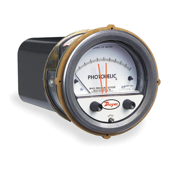
Series A3000 Photohelic
Specifications - Installation and Operating Instructions
The SERIES A3000 PHOTOHELIC
®
combining a time-proven Magnehelic
®
switches. It is designed to measure and control positive, negative or differential pressure
of air or other non-combustible, non-corrosive gases. Gage reading is unaffected by
switch operation. Switch set points are easily adjusted with knobs located on gage
face. Applied pressure and switch set points are fully visible at all times. Deadband is
one pointer width, less than 1% of full scale. Each set point controls a DPDT relay and
both relays can be interlocked to provide variable deadband control.
INSTALLATION
1. Location: Select a clean, dry, vibration-free location where ambient temperatures
will be between 20 and 120°F (-6.67 and 48.9°C). Tubing supplying pressure to the
instrument can be practically any length but long runs will increase response time
slightly.
2. Position: The PHOTOHELIC
Switch/Gage is factory calibrated for use with scale
®
in a vertical plane. Operation at other angles may affect accuracy and/or require zero
adjustment. Most models can be specially calibrated at the factory for other positions
if specified at time of ordering. Ranges below 1 in w.c. must be used only with scale
vertical.
3. Mounting: The PHOTOHELIC
Switch/Gage is normally mounted before making
®
Electrical Connections. The electrical enclosure is removable at any time regardless of
mounting method.
(A) Panel Mounting: Normal mounting is flush or through panel as shown in Figure B.
Allow 4-3/8˝ (111.13 mm) clearance behind the unit for removal of electrical enclosure.
Make a 4-13/16˝ (122.24 mm) diameter hole in panel. Insert the PHOTOHELIC
Switch/Gage unit from front of panel and slip mounting ring over case from behind
with stepped side facing rear. Fit the snap ring into narrow groove at back edge of the
bezel. Thread four 6-32 x 1-1/4˝ mounting screws into tapped holes in mounting ring
and seat it against snap ring. Tighten screws against back of panel. See Figure B.
Ø4-13/16 [122.24]
HOLE REQUIRED FOR
PANEL MOUNTING
DWYER INSTRUMENTS, INC.
P.O. BOX 373 • MICHIGAN CITY, INDIANA 46360, U.S.A.
Switch/Gage is a versatile 2-in-1 instrument
differential pressure gage with low/high pressure
SNAP RING GROOVE
1/2 NPT(M) PRESSURE CONNECTION.
SINGLE HIGH PRESSURE CONNECTION
FOR SERIES 36000S MODELS.
Figure B
Differential Pressure Switch/Gage
®
2-1/2 [63.50]
2-1/16 [52.39]
1/8 FEMALE NPT HIGH
PRESSURE CONNECTION
2 [50.80]
1/8 FEMALE NPT LOW
PRESSURE CONNECTION
Ø4-3/4
[120.65]
3-7/8 SQ
[98.43]
CONNECTION
3-7/8 [98.43]
5-1/8 [130.18]
7-5/8 [193.68]
4-3/8 [111.13]
HOUSING REMOVAL
Note: Detailed dimension drawings are available from our Customer Service Dept. for
PHOTOHELIC
switch/gages as installed in two optional enclosures. For weatherproof
®
housing, request no. 13-700132-00. /For explosion-proof housing, request no. 13-
700113-01.
SPECIFICATIONS
GAGE SPECIFICATIONS
Service: Air and non-combustible, compatible gases.
Wetted Materials: Consult factory.
Accuracy: ±2% of full scale at 70°F (21.1°C). ±3% on -0 and ±4% on -00 models.
Pressure Limits: -20˝ Hg. to 25 psig (-0.677 to 1.72 bar). MP option; 35 psig
(2.41 bar), HP option; 80 psig (5.52 bar). 36003S – 36010S; 150 psig (10.34 bar).
36020S and higher;1.2 x full scale pressure.
Temperature Limits: 20 to 120°F (-6.67 to 48.9°C) Low temperature option
available.
Process Connections: 1/8˝ female NPT.
Size: 4˝ (101.6 mm) dial face, 5˝ (127 mm) O.D. x 8-1/4˝ (209.55 mm).
Weight: 4 lb (1.81 kg).
SWITCH SPECIFICATIONS
Switch Type: Each setpoint has 2 Form C relays (DPDT).
Repeatability: ±1% of full scale.
Electrical Rating: 10A @ 28 VDC, 10A @ 120, 240 VAC.
Electrical Connections: Screw terminals. Use 167°F (75°C) copper conductors
only.
Power Requirements: 120 VAC, 50/60 Hz; 240 VAC & 24 VAC Power optional.
Mounting Orientation: Diaphragm in vertical position. Consult factory for other
position orientations.
Set Point Adjustment: Adjustable knobs on face.
Agency Approvals: CE, CSA, UL.
®
Phone: 219/879-8000
Fax: 219/872-9057
Bulletin B-33-A
(4) 6-32 HOLES
EQUALLY SPACED ON
A 5-1/8 [130.18] B.C.
1-1/4
[31.75]
Ø4-47/64
[120.25]
Ø5
[127.00]
5/8 [15.88]
5/8 [15.88]
5-1/2 [139.70] O.D.
6-3/8 [161.93]
PANEL MAX
MOUNTING RING
3/16 [4.76]
Figure A
www.dwyer-inst.com
e-mail: info@dwyermail.com
Ø4 [101.60]
FACE
Advertisement
Table of Contents

Related Manuals for Dwyer Instruments Series A3000 Photohelic


Summary of Contents for Dwyer Instruments Series A3000 Photohelic
- Page 1 PHOTOHELIC switch/gages as installed in two optional enclosures. For weatherproof ® housing, request no. 13-700132-00. /For explosion-proof housing, request no. 13- 700113-01. The SERIES A3000 PHOTOHELIC Switch/Gage is a versatile 2-in-1 instrument ® SPECIFICATIONS combining a time-proven Magnehelic differential pressure gage with low/high pressure ®...
- Page 2 This will allow the reference pressure to enter. In this case, installation of a Dwyer Instruments, Inc. No. A-331 Filter Vent Plug or similar fitting in the reference pressure tap is recommended to reduce the possibility of dust entering the instrument.
- Page 3 ELECTRICAL CONNECTIONS Section E contains the power connections for the control unit transformer primary. 1. Cover: The amplifier-relay unit has an easy to remove housing. Remove the three The transformer in turn supplies reduced voltage power for the LED, phototransistor, (3) screws as shown in Figure H and slide the housing off.
- Page 4 Contact customer service to receive a switch or push button to the circuit as described in paragraph 6 above. return goods authorization (RGA) number before shipping. ©Copyright 2017 Dwyer Instruments, Inc. Printed in U.S.A. 1/17 FR# 440202-04 Rev. 6 DWYER INSTRUMENTS, INC.
Need help?
Do you have a question about the Series A3000 Photohelic and is the answer not in the manual?
Questions and answers