Table of Contents
Advertisement
Available languages
Available languages
Quick Links
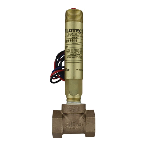
The Series V6 FLOTECT
Flow Switch is an inexpensive, explosion-proof flow
®
switch for use on air, water or other compatible gases and liquids. Three configura-
tions are available - 1. Factory installed in a tee. 2. With a trimmable vane for field
adjustment and installation in a suitable tee. 3. Low flow models with an integral tee
and adjustable valve. All are available with an optional enclosure which is UL and
CSA listed, or Directive 94/9/EC (ATEX) compliant for
II 2 G Ex d IIC T6 Gb
Process Temp≤75°C or IECEx compliant for Ex d IIC T6 Gb Process Temp ≤ 75°C.
INSTALLATION
Unpack and remove any packing material found inside lower housing or tee.
Switch can be installed in any position but the actuation/deactuation flow rates in
the charts are based on horizontal pipe runs and are nominal values. For more pre-
cise settings, units can be factory calibrated to specific flow rates.
V6 Models with Tee are supplied in 1/2˝ - 2˝ NPT sizes. Install in piping with arrow
pointing in direction of flow.
V6 Low Flow Models have 1/2˝ NPT connections and are field adjustable. Install
in piping with arrow pointing in direction of flow. To adjust, loosen the four socket
head cap screws on bottom. The adjustment valve rotates 90° between "O" (open)
and "C" (closed). See flow charts for approximate ranges. Tighten screws once the
required flow rate has been set.
V6 with Field Trimmable Vane. These models enable the installer to choose ap-
proximate actuation/deactuation points by trimming the full size vane at appropriate
letter-designated marks on a removable template. Flows are defined in the following
charts. Note that the charts are based on either brass or cast iron reducing tees or
stainless or forged steel straight tees with bushings where necessary. Install in piping
with arrow pointing in direction of flow.
When bushings are used, they must be back drilled to allow proper clearance for
unrestricted vane travel. Bore the I.D. to 13/16˝ (20 mm) on 1/2˝ x 3/4˝ bushings or
1˝ (25 mm) on larger bushings. The depth of the bore must leave internal threads
9/16˝ (14 mm) high for proper engagement between the lower housing of the switch
and the bushing. Check for proper vane travel and switch operation after installa-
tion.
W.E. ANDERSON DIV., DWYER INSTRUMENTS, INC.
P.O. BOX 358 • MICHIGAN CITY, INDIANA 46361 U.S.A.
Series V6 FLOTECT
Specifications - Installation and Operating Instructions
Flow Switch
®
SPECIFICATIONS
Service: Gases or liquids compatible with wetted materials.
Wetted Materials: Standard V6 Models: Vane: 301 SS; Lower Body: brass or 303
SS; Magnet: ceramic; Other: 301, 302 SS; Tee: brass, iron, forged steel, or 304 SS.
V6 Low Flow Models: Lower Body: brass or 303 SS; Tee: brass or 304 SS; Magnet:
ceramic; O-ring: Buna-N standard, Fluoroelastomer optional; Other: 301, 302 SS.
Temperature Limits: -4 to 220°F (-20 to 105°C) Standard, MT high temperature
option 400°F (205°C) (MT not UL, CSA, ATEX or IECEx) ATEX Compliant AT and
IECEx IEC Option, Ambient Temperature -4 to 167°F (-20 to 75°C) Process Tem-
perature: -4 to 220°F (-20 to 105°C).
Pressure Limit: Brass lower body with no tee models 1000 psig (69 bar), 303 SS
lower body with no tee models 2000 psig (138 bar). Brass tee models 250 psi (17.2
bar), iron tee models 1000 psi (69 bar), forged and stainless steel tee models 2000
psi (138 bar), low flow models 1450 psi (100 bar).
Enclosure Rating: Weatherproof and Explosion-proof. Listed with UL and CSA for
Class I, Groups A, B, C and D; Class II, Groups E, F, and G. (Group A on stainless
steel body models only).
0344
II 2 G Ex d IIC T6 Gb Process Temp≤75°C Alternate Temperature Class
T5 Process Temp≤90°C, 115°C (T4) Process Temp ≤105°C consult factory. EC-type
Certificate No.: KEMA 04ATEX2128.
ATEX Standards: EN 60079-0: 2009; EN 60079-1: 2007.
IECEx Certified: For Ex d IIC T6 Gb Process Temp≤75°C Alternate Temperature
Class T5 Process Temp≤90°C, 115°C (T4) Process Temp≤105°C consult factory.
IECEx Certificate of Conformity: IECEx DEK 11.0039;
IECEx Standards: IEC 60079-0: 2007; IEC 60079-1: 2007;
Switch Type: SPDT snap switch standard, DPDT snap switch optional.
Electrical Rating: UL models: 5A @125/250 VAC. CSA, ATEX and IECEx models:
5A @ 125/250 VAC (V~); 5A res., 3A ind. @ 30 VDC (V ). MV option: .1A @ 125
VAC (V~). MT option: 5A @125/250 VAC (V~). [MT option not UL, CSA, ATEX or
IECEx].
Electrical Connections: UL models: 18 AWG, 18˝ (460 mm) long. ATEX/CSA
/IECEx models: terminal block.
Upper Body: Brass or 303 stainless steel.
Conduit Connections: 3/4˝ male NPT standard, 3/4˝ female NPT on junction box
models.
Process Connection: 1/2˝ male NPT on models without a tee.
Mounting Orientation: Switch can be installed in any position but the actuation/de-
actuation flow rates in the charts are based on horizontal pipe runs and are nominal
values.
Set Point Adjustment: Standard V6 models none. Without tee models vane is trim-
mable. Low flow models are field adjustable in the range shown. See set point
charts on opposite page.
Weight: 2 to 6 lb (.9 to 2.7 kg) depending on construction.
Options not Shown: Custom calibration, bushings, PVC tee, reinforced vane,
DPDT relays.
ELECTRICAL CONNECTIONS
Connect wire leads in accordance with local electrical codes and switch action re-
quired. N.O. contacts will close and N.C. contacts will open when flow increases to
the actuation point. They will return to "normal" condition when flow decreases to
the deactuation point. Black = Common, Blue = Normally Open and Red = Normally
Closed.
For units supplied with both internal ground and external bonding terminals, the
ground screw inside the housing must be used to ground the control. The external
bonding screw is for supplementary bonding when allowed or required by local code.
When external bonding conductor is required, conductor must be wrapped a mini-
mum of 180° about the external bonding screw. See below. Some CSA listed models
are furnished with a separate green ground wire. Such units must be equipped with
a junction box, not supplied but available on special order.
LOCKWASHER
SCREW
CLAMP
FRONT VIEW DETAIL
Phone: 219/879-8000
Fax: 219/872-9057
Bulletin E-22
CONDUCTOR
SIDE VIEW DETAIL
www.dwyer-inst.com
e-mail: info@dwyer-inst.com
Advertisement
Table of Contents

Related Manuals for Dwyer Instruments FLOTECT V6 series


Summary of Contents for Dwyer Instruments FLOTECT V6 series
- Page 1 Check for proper vane travel and switch operation after installa- tion. CLAMP FRONT VIEW DETAIL SIDE VIEW DETAIL Phone: 219/879-8000 www.dwyer-inst.com W.E. ANDERSON DIV., DWYER INSTRUMENTS, INC. Fax: 219/872-9057 e-mail: info@dwyer-inst.com P.O. BOX 358 • MICHIGAN CITY, INDIANA 46361 U.S.A.
-
Page 2: Maintenance
Disconnect device from the supply circuit before opening to prevent ignition of hazardous atmosphere. Repairs to be conducted by Dwyer Instruments, Inc. Units in need of repair should be returned to the factory prepaid. V6EPB-B-S-2-B-MT flow switch; brass upper housing, brass lower housing, brass Example tee with 3/4˝... - Page 3 Air - Brass or Cast Iron Reducing Tee V6 With Field Trimmable Vane Approximate actuation/deactuation flow rates Cold Water - Brass or Cast Iron Reducing Tee SCFM upper, NM /M lower Approximate actuation/deactuation flow rates GPM upper, M /HR lower 1-1/2˝...
- Page 4 "A" Terminal Connections CSA, ATEX Enclosures V6 with Tee and CSA, "A" ATEX Conduit Enclosure V6 with Tee W.E. ANDERSON DIV., DWYER INSTRUMENTS, INC. Phone: 219/879-8000 www.dwyer-inst.com Fax: 219/872-9057 e-mail: info@dwyer-inst.com P.O. BOX 358 • MICHIGAN CITY, INDIANA 46361 U.S.A.
-
Page 5: Installation
CLAMP VUE DE FACE DÉTAILLÉE VUE DE CÔTÉ DÉTAILLÉE FRONT VIEW DETAIL SIDE VIEW DETAIL Téléphone : 219/879-8000 www.dwyer-inst.com W.E. ANDERSON DIV., DWYER INSTRUMENTS, INC. Fax : 219/872-9057 e-mail : info@dwyer-inst.com P.O. BOX 358 • MICHIGAN CITY, INDIANA 46361 ÉTATS-UNIS. -
Page 6: Entretien
Pour éviter toute ignition en atmosphère dange- reuse, débrancher le dispositif de l’alimentation électrique avant de l’ouvrir. Les ré- parations doivent être réalisées par Dwyer Instruments, Inc. Les unités qui ont besoin d’être réparées doivent être renvoyées aux ateliers de l’usine. - Page 7 Air - Té réducteur en laiton ou en fonte V6 avec palette graduée éboutable Débits approximatifs d’Activation/désactivation Eau froide - Té réducteur en laiton ou en fonte SCFM en haut, NM /M en bas Débits approximatifs d’Activation/désactivation GPM en haut, M /HR en bas 3/4˝...
- Page 8 Bornes de raccordement Boîtiers CSA, ATEX V6 avec té et "A" boîtier CSA, ATEX V6 avec té W.E. ANDERSON DIV., DWYER INSTRUMENTS, INC. Téléphone : 219/879-8000 www.dwyer-inst.com Fax : 219/872-9057 e-mail : info@dwyer-inst.com P.O. BOX 358 • MICHIGAN CITY, INDIANA 46361 ÉTATS-UNIS.
- Page 9 Muffe). Nach der Installation prüfen Sie, ob das Paddel ordnungsgemäß schwingen Klemme CLAMP kann. Seitenansicht Vorderansicht FRONT VIEW DETAIL SIDE VIEW DETAIL Telefon: +1 219/879-8000 www.dwyer-inst.com W.E. ANDERSON DIV., DWYER INSTRUMENTS, INC. Fax: +1 219/872-9057 E-Mail: info@dwyer-inst.com P.O. BOX 358 • MICHIGAN CITY, INDIANA 46361 U.S.A.
-
Page 10: Wartung
Schmutz, Staub und Wettereinflüssen zu schützen. Lösen Sie immer die Span- nungsversorgung, bevor Sie den Schalter öffnen, um Arbeiten an der Elektrik vor- zunehmen. Reparaturen sind von Dwyer Instruments, Inc. vorzunehmen. Senden Sie reparaturbedürftige Teile mit Vorauszahlung an den Betrieb. - Page 11 Luft - Messing- oder Stahl-T-Stück V6 mit einstellbarem Paddel Ungefährer Ein-/Ausschaltpunkt Kaltes Wasser - Messing oder Stahl T-Stueck SCFM oben, NM /M unten Ungefährer Ein-/Ausschaltpunkt GPM oben M /HR unten 3/4˝ NPT 1-1/2˝ NPT 2˝ NPT 1/2˝ NPT 1˝ NPT Platte 1/2˝...
- Page 12 "A" Klemmleisten für CSA- und ATEX-Modelle V6 mit T-Stück für CSA-, ATEX-Gehäuse "A" V6 mit T-Stück W.E. ANDERSON DIV., DWYER INSTRUMENTS, INC. Telefon: +1 219/879-8000 www.dwyer-inst.com Fax: +1 219/872-9057 E-Mail: info@dwyer-inst.com P.O. BOX 358 • MICHIGAN CITY, INDIANA 46361 U.S.A.
-
Page 13: Instalación
CLAMP TORNILLO DETALLE DE LA VISTA FRONTAL FRONT VIEW DETAIL DETALLE DE LA VISTA LATERAL SIDE VIEW DETAIL W.E. ANDERSON DIV., DWYER INSTRUMENTS, INC. Teléfono: 219/879-8000 www.dwyer-inst.com Fax: 219/872-9057 correo electrónico: P.O. BOX 358 • MICHIGAN CITY, INDIANA 46361 U.S.A. -
Page 14: Mantenimiento
Desconecte el dispositivo del circuito de la fuente de alimentación antes de abrirlo, a fin de evitar incendios en una atmósfera peligrosa. Las reparaciones deben ser realizadas por Dwyer Instruments, Inc. Las unidades para reparación deben enviarse prepagadas a la fábrica. - Page 15 Aire: “T” reductora de latón o de hierro fundido V6 con paleta recortable en campo Caudales aproximados de actuación/desactuación Agua fría: “T” reductora de latón o de hierro fundido Superior en SCFM, inferior en NM Caudales aproximados de actuación/desactuación Superior en GPM, inferior en M 3/4˝...
- Page 16 V6 con “T” y caja de conductor CSA, ATEX "A" V6 con “T” ©Copyright 2011 Dwyer Instruments, Inc. Printed in U.S.A. 11/11 FR# 82-440805-10 Rev. 4 W.E. ANDERSON DIV., DWYER INSTRUMENTS, INC. Teléfono: 219/879-8000 www.dwyer-inst.com Fax: 219/872-9057 correo electrónico: P.O. BOX 358 • MICHIGAN CITY, INDIANA 46361 U.S.A.
Need help?
Do you have a question about the FLOTECT V6 series and is the answer not in the manual?
Questions and answers